LMH250RC - Lighting IBIZA SOUND - Free user manual and instructions
Find the device manual for free LMH250RC IBIZA SOUND in PDF.
Document temporarily unavailable
The manual is currently being transferred to our new server. It will be accessible again in a few hours. Thank you for your patience.
| Product type | LED Moving Head Beam |
| Brand | Ibiza Sound |
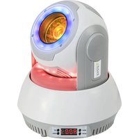
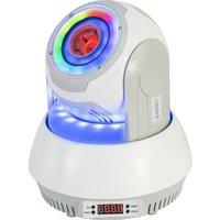
| Model | LMH250RC |
| Power supply | 100-240 V~ 50/60 Hz |
| Light source | 1 CREE 10 W LED, 4-in-1 (RGGB) |
| Main functions | Automatic, sound-active, master/slave, DMX512, strobe, IR control |
| DMX channels | 4 or 13 channels |
| DMX connectors | Male XLR 3-pin input, female XLR 3-pin output |
| Mounting | On mounting bracket, can be installed in any position |
| Ventilation | Minimum distance of 50 cm from any surface, ventilation slots unobstructed |
| Max. ambient temperature | 40 °C |
| Fuse | Replace with fuse of same rating, accessible via fuse holder |
| Remote control | Infrared included |
| Maintenance and cleaning | Disconnect before maintenance, use a dry cloth |
| Safety | Earth connection, do not expose to rain, do not look directly at the light source |
| Repairability | Contact authorized technical service, use identical spare parts |
Frequently Asked Questions - LMH250RC IBIZA SOUND
User questions about LMH250RC IBIZA SOUND
0 question about this device. Answer the ones you know or ask your own.
Ask a new question about this device
Download the instructions for your Lighting in PDF format for free! Find your manual LMH250RC - IBIZA SOUND and take your electronic device back in hand. On this page are published all the documents necessary for the use of your device. LMH250RC by IBIZA SOUND.