
STAR-WASH - Lighting IBIZA SOUND - Free user manual and instructions
Find the device manual for free STAR-WASH IBIZA SOUND in PDF.

| Product type | Motorized LED effect projector |
| Brand | Ibiza Sound |
| Model | STAR-WASH |
| Power supply | 90-240 V~, 50/60 Hz |
| Power consumption | Not specified |
| Brightness | 7 950 lumens |
| Color temperature | 8 500 K |
| Color rendering index (CRI) | 90 |
| Beam angle | 45° |
| Pan movement | 540° |
| Tilt movement | 180° |
| Control modes | DMX512, master/slave, automatic, sound |
| Number of DMX channels | 14 or 19 |
| DMX addressing | d001-d512 |
| Sound sensitivity | 0-99 |
| Fuse | Replace with an identical model |
| Minimum safety distance | 120 cm from surfaces |
| Maximum ambient temperature | 35 °C |
| Usage | Indoor only |
| Protection class | I (grounding mandatory) |
| Protection rating | Not specified |
| Housing material | Not specified |
| Color | Black (typical) |
| Dimensions (approx.) | 250 x 250 x 350 mm (estimate) |
| Weight (approx.) | 3.0 kg (estimate) |
| Cleaning of optics | Soft cloth and glass cleaner, external optics every 3 weeks, internal optics every 1-2 months |
| Light source | Non-replaceable LED (replace the unit at end of life) |
| Safety cable required | Yes, capacity 12 times the weight of the unit |
Frequently Asked Questions - STAR-WASH IBIZA SOUND
User questions about STAR-WASH IBIZA SOUND
0 question about this device. Answer the ones you know or ask your own.
Ask a new question about this device
Download the instructions for your Lighting in PDF format for free! Find your manual STAR-WASH - IBIZA SOUND and take your electronic device back in hand. On this page are published all the documents necessary for the use of your device. STAR-WASH by IBIZA SOUND.
USER MANUAL STAR-WASH IBIZA SOUND
natural_image
Abstract pattern of orange dots forming a stylized letter 'U' shape (no text or symbols)
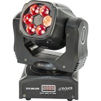
WASH MOVING HEAD
WITH 30W GOBO SPOT & LED RING
Ref.
STAR-WASH

natural_image
Black remote control room with illuminated circular light source and digital display (no visible text or symbols)
natural_image
3D rendering of a remote control device with illuminated screen and digital display (no text or symbols visible)STAR-WASH-BL
Code: 15-1957 Code: 15-1958
STAR-WASH-WH
MANUAL
WASH MOVING HEAD WITH 30W GOBO SPOT & LED RING INSTRUCTION MANUAL
CONTENTS OF THE CARTON:
- 1 x Moving head
- 1x Mains lead
1x User Manual
UNPACKING INSTRUCTIONS
Immediately upon receiving a fixture, carefully unpack the carton, check the contents to ensure that all parts are present and have been received in good condition. Notify the freight company immediately and retain packing material for inspection if any parts appear to be damaged from shipping or the carton itself shows signs of mishandling. Keep the carton and all packing materials. In the event that a fixture must be returned to the factory, it is important that the fixture be returned in the original factory box and packing.
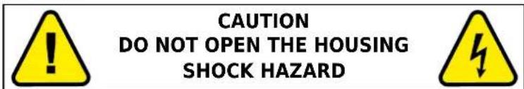
EXPLANATION OF SYMBOLS
The triangle containing a lightning symbol is used to indicate whenever your health is at risk (due to electrocution, for example).
An exclamation mark in a triangle indicates particular risks in handling or operating the appliance.
CE The unit complies with CE standards
For indoor use only
Protection class I. Requires an earth connection
Minimum distance between the appliance and other objects
Don't stare into the light beam
IMPORTANT SAFETY INSTRUCTIONS AND DANGER WARNINGS
- Please read these instructions carefully, they include important information about the installation, usage and maintenance of this product.
- Please keep this User Guide for future reference. If you sell the unit to another user, be sure that he also receives this instruction booklet.
• Always make sure that you are connecting to the proper voltage, and that the line voltage you are connecting to is not higher than that stated on the decal or rear panel of the fixture.
• This product is intended for indoor use only! - It is essential that the device is earthed. A qualified person must carry out the electric connection.
- To prevent risk of fire or shock, do not expose fixture to rain or moisture. Make sure there are no flammable materials close to the unit while operating.
- The unit must be installed in a location with adequate ventilation, at least 1.2m from adjacent surfaces. Be sure that no ventilation slots are blocked.
• Always disconnect from power source before servicing or replacing fuse and be sure to replace with same fuse size and type. - Secure fixture to fastening device using a safety chain. Never carry the fixture solely by its head. Use its carrying handles.
• Maximum ambient temperature (Ta) is 35^ C. Do not operate the fixture at temperatures higher than this. -
In the event of a serious operating problem, stop using the unit immediately. Never try to repair the unit by yourself. Repairs carried out by unskilled people can lead to damage or malfunction. Please contact the nearest authorized technical assistance center. Always use the same type of spare parts.
-
Don't connect the device to a dimmer pack.
• Make sure the power cord is never crimped or damaged. - Never disconnect the power cord by pulling or tugging on the cord.
- Avoid direct eye exposure to the light source while it is on.
- The product is for decorative purposes only and not suitable as a household room illumination.
- The light source of this luminaire is not replaceable. When it reaches the end of its life time, the whole unit must be discarded.
- DISCONNECT DEVICE: Where the MAINS plug or an appliance coupler is used as the disconnect device, the disconnect device shall remain readily operable.
INSTALLATION
The unit should be mounted via its screw holes on the bracket. Always ensure that the unit is firmly fixed to avoid vibration and slipping while operating. Always ensure that the structure to which you are attaching the unit is secure and able to support a weight of 10 times of the unit's weight. Also always use a safety cable that can hold 12 times the weight of the unit when installing the fixture.
The equipment must be fixed by professionals at a place where is out of the reach of people and where nobody can pass by or under it.
FUSE REPLACEMENT
- With a flat head screwdriver wedge the fuse holder out of its housing.
- Remove the damaged fuse from its holder and replace with exactly the same type of fuse.
- Insert the fuse holder back in its place and reconnect power.
- The fuse is located inside this compartment. Remove using a flat head screwdriver.
FIXTURE LINKING
You will need a serial data link to run light shows of one or more fixtures using a DMX-512 controller or to run synchronized shows on two or more fixtures set to a master/slave operating mode. The combined number of channels required by all fixtures on a serial data link determines the number of fixtures that the data link can support.
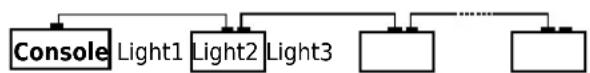
flowchart
graph TD
    A["Console"] --> B["Light1"]
    A --> C["Light2"]
    A --> D["Light3"]
    C --> E["..."]
    D --> F["..."]
Important: Fixtures on a serial/data link must be daisy chained in one single line. Maximum recommended serial data link distance: 100 meters. Maximum recommended number of fixtures on a serial data link: 32 fixtures
CABLE CONNECTORS
Cabling must have a male XLR connector on one end and a female XLR connector on the other end.
DMX CONNECTOR CONFIGURATION
Termination reduces signal errors. To avoid signal transmission problems and interference, it is always advisable to connect a DMX signal terminator.
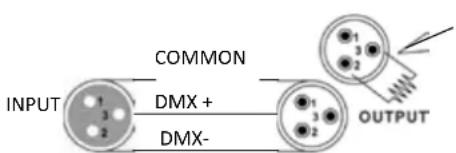
Resistance 120 ohm 1/4w between pin 2 (DMX-) and pin 3 (DMX+) of the last fixture.
CAUTION
Do not allow contact between the common and the fixture's chassis ground. Grounding the common can cause a ground loop, and your fixture may perform erratically. Test cables with an ohm meter to check correct polarity and to make sure the pins are not grounded or shorted to the shield or each other.
SETTING UP A DMX SERIAL DATA LINK
- Connect the (male) 3 pin connector side of the DMX cable to the output (female) 3 pin connector of the controller.
- Connect the end of the cable coming from the controller which will have a (female) 3 pin connector to the input connector of the next fixture consisting of a (male) 3 pin connector.
- Then, proceed to connect from the output as stated above to the input of the following fixture and so on.
MASTER/SLAVE FIXTURE LINKING
-
Connect the (male) 3 pin connector side of the DMX cable to the output (female) 3 pin connector of the first fixture.
-
Connect the end of the cable coming from the first fixture which will have a (female) 3 pin connector to the input connector of the next fixture consisting of a (male) 3 pin connector. Then, proceed to connect from the output as stated above to the input of the following fixture and so on
Often, the set up for Master-Slave and Stand-alone operation requires that the first fixture in the chain be initialized for this purpose via either settings in the control panel or DIP-switches. Secondarily, the fixtures that follow may also require a slave setting. Please consult the "Operating Instructions" section in this manual for complete instructions for this type of setup and configuration.
OPERATING INSTRUCTIONS
NAVIGATION THROUGH THE CONTROL PANEL
Access control panel functions using the four panel buttons located directly underneath the LCD Display..
Button Function
| MENU Used to access the menu or to return to a previous menu option |
| UP Scrolls through menu options in ascending order |
| DOWN Scrolls through menu options in descending order |
| ENTER Used to select and store the current menu or option within a me |
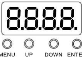
When a menu function is selected, the display will show immediately the first available option for the selected menu function. To select a menu item, press
MENU MAP
Press the
| Addr d001-d512 512 address setting | ||
| CHnd | 19CH 19 channel settings | |
| 14CH 14 channel settings | ||
| SLnd | Auto Automatic mode | |
| Soun Sound-controlled operation | ||
| SHnd | SH 0 Effect 0 (recommended) | |
| SH 1 Effect 1 | ||
| SH 2 Effect 2 | ||
| SH 3 Effect 3 | ||
| SEnS 0-99 Sound sensitivity adjustment | ||
| LED | OFF | Screen off after 5 seconds of inactivity |
| ON | Screen always on | |
| dISP | no | Display reverse |
| YES | Display positive | |
| rPAN | no | X motor forward |
| YES | X motor reverse | |
| rTiL | no | Y motor forward |
| YES | Y motor reverse | |
| RGB | OFF | SMD off |
| ON | SMD on | |
| Load | no | |
| YES | Restore factory settings | |
| REST YES System reset | ||
TABLE OF DMX CHANNELS: SEE AT THE END OF THE MANUAL
FIXTURE CLEANING
The cleaning of internal and external optical lenses and/or mirrors must be carried out periodically to optimize light output. Cleaning frequency depends on the environment in which the fixture operates: damp, smoky or particularly dirty surrounding can cause greater accumulation of dirt on the unit's optics.
- Clean with soft cloth using normal glass cleaning fluid.
• Always dry the parts carefully. - Clean the external optics at least every 20 days. Clean the internal optics at least every 30/60 days.
SPECIFICATIONS
Power supply....90-240V\~50/60Hz
Consumption....100W
Light sources....1 white 30W LED + 6 x 8W RGBW LEDs + 18 x 0.2W RGB LEDs
Colour temperature....8500°K
Brightness....7950 lm
CRI 90
Beam angle....45°
Pan / Tilt....540° / 180°
Strobe 20 flashes/sec.
Dimensions 200 x 200 x 250mm
Weight....3kg

Electric products must not be put into household waste. Please bring them to a recycling centre. Ask your local authorities or your dealer about the way to proceed.
LYRE WASH AVEC SPOT 30W A GOBOS ET ANNEAU LUMINEUX MANUEL D'UTILISATION
CONTENU DE L'EMBALLAGE:
REPLACEMENT DU FUSIBLE
Consommation....100W
Sources lumineuses ....1 LED blanche de 30W + 6 LED RGBW de 8W + 18 LED RGB de 0.2W
Strobo 20 flash/sec.
Dimensions 200 x 200 x 250mm
Poids 3kg

WASH MOVING HEAD MIT 30W GOBO SPOT & LED RING
BEDIENUNGSANLEITUNG
VERPACKUNGSINHALT:
Strobe ....20 flitsen/sec.
Afmetingen 200 x 200 x 250mm
Gewicht....3kg

CABEZA MOVIL WASH CON SPOT 30W CON GOBOS Y ANILLO LUMINOSO
MANUAL DE USO


- WASH MOVING HEAD
- WITH 30W GOBO SPOT & LED RING
- Ref.
- STAR-WASH
- MANUAL
- WASH MOVING HEAD WITH 30W GOBO SPOT & LED RING INSTRUCTION MANUAL
- CONTENTS OF THE CARTON:
- UNPACKING INSTRUCTIONS
- EXPLANATION OF SYMBOLS
- IMPORTANT SAFETY INSTRUCTIONS AND DANGER WARNINGS
- INSTALLATION
- FUSE REPLACEMENT
- FIXTURE LINKING
- CABLE CONNECTORS
- DMX CONNECTOR CONFIGURATION
- CAUTION
- SETTING UP A DMX SERIAL DATA LINK
- MASTER/SLAVE FIXTURE LINKING
- OPERATING INSTRUCTIONS
- NAVIGATION THROUGH THE CONTROL PANEL
- MENU MAP
- TABLE OF DMX CHANNELS: SEE AT THE END OF THE MANUAL
- FIXTURE CLEANING
- SPECIFICATIONS
- LYRE WASH AVEC SPOT 30W A GOBOS ET ANNEAU LUMINEUX MANUEL D'UTILISATION
- CONTENU DE L'EMBALLAGE:
- REPLACEMENT DU FUSIBLE
- WASH MOVING HEAD MIT 30W GOBO SPOT & LED RING
- BEDIENUNGSANLEITUNG
- VERPACKUNGSINHALT:
- CABEZA MOVIL WASH CON SPOT 30W CON GOBOS Y ANILLO LUMINOSO
- MANUAL DE USO
Brand : IBIZA SOUND
Model : STAR-WASH
Category : Lighting