CNS 2500 Plus LCD - Wall electric heater STIEBEL ELTRON - Free user manual and instructions
Find the device manual for free CNS 2500 Plus LCD STIEBEL ELTRON in PDF.

| Brand | Stiebel Eltron |
| Model | CNS 2500 Plus LCD |
| Type | Wall-mounted electric convector |
| Nominal thermal power | 2500 W |
| Electrical supply | 230 V ~ 50 Hz, 1/N/PE |
| Rated current | 10.9 A |
| Dimensions (H x W x D) | 450 x 894 x 100 mm |
| Weight | 9.5 kg |
| Temperature adjustment range | 5 °C to 30 °C |
| Operating modes | Comfort, Reduced, Frost protection, Standby |
| Programmer | Weekly (3 programs: Pro1, Pro2, Pro3) |
| Special functions | Open window detection, Adaptive start, Control locking |
| Display | Backlit LCD |
| Protection rating | IP24 |
| Protection class | I |
| Color | Alpine white |
| Installation | Wall-mounted, with mounting bracket supplied |
| Electrical connection | Schuko plug with earth or fixed connection by a professional |
| Cleaning | Damp cloth, non-abrasive products |
| Spare parts | Stiebel Eltron originals recommended |
| Warranty | According to local subsidiary conditions |
Frequently Asked Questions - CNS 2500 Plus LCD STIEBEL ELTRON
User questions about CNS 2500 Plus LCD STIEBEL ELTRON
0 question about this device. Answer the ones you know or ask your own.
Ask a new question about this device
Download the instructions for your Wall electric heater in PDF format for free! Find your manual CNS 2500 Plus LCD - STIEBEL ELTRON and take your electronic device back in hand. On this page are published all the documents necessary for the use of your device. CNS 2500 Plus LCD by STIEBEL ELTRON.
USER MANUAL CNS 2500 Plus LCD STIEBEL ELTRON
natural_image
White rectangular electronic device with ventilation grilles and a 'STROCCION' logo on the front panel (no other text or symbols visible)| CNS500PlusLCD | CNS750PlusLCD | CNS1000PlusLCD | CNS1500PlusLCD | CNS2000PlusLCD | CNS2500PlusLCD | CNS3000PlusLCD |
2.1 Symbols in this document 16
2.2 Symbols on the appliance.... 16
2.3 Units of measurement 16
3 Safety.... 16
3.1 Structure of the warning notices....16
3.2 Intended use 17
3.3 Foreseeable misuse.... 17
3.4 Safety instructions.... 17
4 Appliance description.... 17
4.1 Standard delivery 17
5 Installation (qualified contractors).... 17
5.1 Installation site.... 17
5.2 Installing the wall mounting bracket 18
5.3 Installing the appliance.... 19
5.4 Electrical connection 19
6 Commissioning (qualified contractors) 19
7 Operation.... 20
7.1 Programming unit.... 20
7.2 Operating buttons 20
7.3 Display.... 20
7.4 Standby.... 20
8 Settings.... 21
8.1 Default display 21
8.2 Standard menu 21
8.3 Configuration menu 21
9 Cleaning (users).... 22
10 Troubleshooting (users) 23
11 Troubleshooting (qualified contractors).... 23
12 Shutting down the system 23
13 Removal.... 23
14 Specification 23
14.1 Dimensions and connections 23
14.2 Energy consumption data.... 24
14.3 Data table 25
15 Guarantee.... 25
16 Environment and recycling.... 25
1 Special information
- Keep children under the age of 3 away from the appliance if constant supervision cannot be guaranteed.
- Children from the age of 3 to 8 may switch the appliance on and off, provided they are supervised or have been instructed in the safe operation of the appliance and understand any risks that may result. This is subject to the appliance having been installed as described. Children from the age of 3 to 8 must not plug the power cable into its socket or regulate the appliance.
- This appliance may be used by people (including children) with reduced physical, sensory or mental capabilities or a lack of experience and knowledge, provided that they are supervised or have been instructed on how to use the appliance safely by a person responsible for their safety.
- Children must be supervised to ensure that they do not play with the appliance.
- In closed rooms, temperatures can rapidly reach high levels. Ensure constant supervision if the appliance is operated in a small room and the persons within that room cannot regulate the appliance or leave the room on their own.
- Observe all applicable national and regional regulations and instructions.
- Parts of the appliance can get very hot and may cause burns. Particular caution is advised when children or vulnerable persons are present.
- To prevent the appliance from overheating, never cover it with anything.
- Never install the appliance directly below a wall socket.
- In the case of a permanent connection, ensure the appliance can be separated from the power supply by an isolator with at least 3 mm omnipolar contact separation.
- To prevent hazards, the power cable must only be replaced (for example if damaged) by a qualified contractor authorised by the manufacturer, using an original spare part.
2 General information

Read these instructions carefully before using the appliance and retain them for future reference.
2.1 Symbols in this document
| Symbol | Meaning |
| This symbol indicates possible property damage, equipment damage, consequential damage or environmental damage. | |
| General information is indicated by the adjacent symbol. | |
| This symbol indicates that you have to do something. | |
| √ | This symbol indicates that you must fulfil certain prerequisites before you perform the following steps. |
| ⇒ | This symbol indicates a result or intermediate result. |
| □□■ | These symbols show you the software menu level (in this example level 3). |
| [▶ 11] | This symbol indicates a reference to the corresponding page number (page 11 in this example). |
2.2 Symbols on the appliance
Symbol Meaning

WARNING Overheating
▶ To prevent the appliance from overheating, never cover it with anything.

▶ To prevent potential hazards, read these instructions carefully before use.

▶ Do not dispose of the appliance as unsorted waste, but take it to separate collection points for reuse and recycling.
2.3 Units of measurement
All measurements are given in mm unless stated otherwise.
3 Safety
3.1 Structure of the warning notices
3.1.1 Section-specific warning notices
Section-specific warning notices apply to all steps in the section.
Injury
CAUTION

Type and source of risk
Consequence(s) of failure to observe the warning notice
▶ Hazard prevention measure(s)
Property damage, consequential losses, environmental pollution
NOTICE

Type and source of risk
Consequence(s) of failure to observe the warning notice
▶ Hazard prevention measure(s)
3.1.2 Embedded warning notices
Embedded warning notices apply only to the step immediately following the notice.
▶ SIGNAL WORD: Consequence(s) of failure to observe the warning notice. Hazard prevention measure(s). Step to which the warning notice refers
3.1.3 Key to symbols
Symbol Type of risk

Injury

Electrocution

Burns, scalding
3.1.4 Signal words
| Signal word | Meaning |
| DANGER Failure to observe this information will result in death or serious injury. | |
| WARNING Failure to observe this information may result in death or serious injury. | |
| CAUTION Failure to observe this information may result in moderate or minor injury. | |
| NOTICE Failure to observe this information may result in property damage, consequential losses or environmental damage. | |
3.2 Intended use
This appliance is designed to heat living spaces.
The appliance is intended for domestic use. It can be used safely by untrained persons. The appliance can also be used in non-domestic environments, e.g. in small businesses, as long as it is used in the same way.
Observation of these instructions and of instructions for any accessories used is also part of the intended use of this appliance.
3.3 Foreseeable misuse
Any other use beyond that described shall be deemed to be outside the intended use.
3.4 Safety instructions
Injury
- Never operate this appliance ...
- if the distance from adjacent objects or other flammable materials would be less than the minimum permissible distance.
-
in rooms where there is at risk of fire or explosion as a result of chemicals, dust, gases or vapours. Ventilate the room sufficiently before heating.
-
in the direct proximity of pipes or receptacles that carry or contain flammable or explosive materials.
-
if an appliance component is damaged, the appliance has fallen over or there is a fault.
-
Never place any flammable, combustible or insulating objects or materials on the appliance or in direct proximity to it.
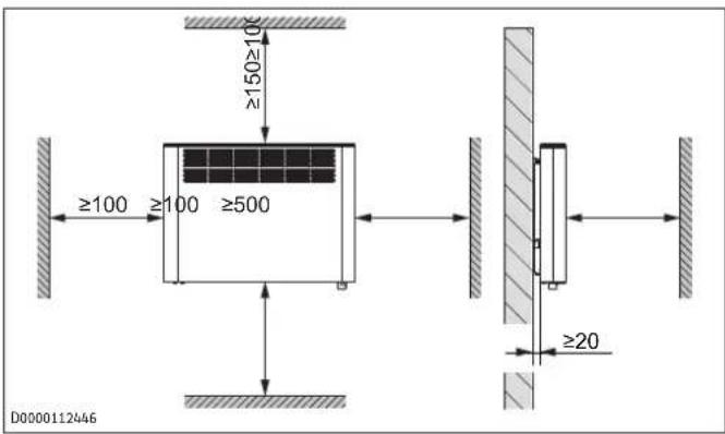
- Ensure that the air intake and discharge are never blocked.
- Never place any objects between the appliance and the wall.
- The appliance is unsuitable for use as a floorstanding appliance. Only ever operate the appliance when it is mounted on the wall mounting bracket supplied (see chapter Installation (qualified contractors) [▶ 17]).
Property damage, consequential losses, environmental pollution
- Ensure that the power cable does not touch the appliance.
- Never stand on the appliance.
- Never operate the appliance in the open air.
- We guarantee trouble-free function and operational reliability only if original accessories and spare parts intended for the appliance are used.
4 Appliance description
The appliance is a wall mounted electric direct heater.
The appliance is suitable for use as a standalone heater or as an interim heater in spring/autumn and as a booster heater for smaller rooms.
The air inside the appliance is heated by a heating element and expelled via natural convection through the air discharge at the top. Cool indoor air is drawn in through the air intake on the underside of the appliance. When the set room temperature is reached, it is maintained by periodic heating.
4.1 Standard delivery
- Wall mounted convector
- Documentation
- 1× wall mounting bracket (hooked into the appliance)
5 Installation (qualified contractors)

Step-by-step guide
Video on installing and commissioning the appliance

5.1 Installation site
CAUTION

Burns
▶ Only mount the appliance on a vertical wall.
NOTICE

Property damage
▶ Never install the appliance directly below a wall socket.
▶ Ensure that the power cable does not touch the appliance.
5.1.1 Installation in bathrooms
WARNING

Electrocution
When installing the appliance in rooms with a bath and/or shower, the appliance must only be connected to a standard safety socket outside safety zones 0, 1 and 2. The standard safety socket must be at least 600 mm away from a bath or shower.
NOTICE

Property damage
If installing the appliance in a bathroom, it must only be installed a sufficient distance away from a bathtub and/or shower. If water gets into electronic components and enclosures, a short circuit may occur or the appliance may be damaged.
During installation, ensure that switches and other operating controls of the appliance cannot be touched by people who are in the bath or shower.
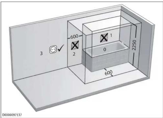
Electrical safety zones in the bathroom
5.1.2 Minimum clearances
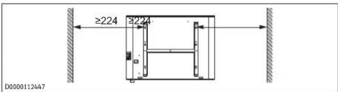
5.2 Installing the wall mounting bracket
The appliance is intended for wall mounting using the wall mounting bracket supplied.

▶ Only mount the appliance horizontally on the wall.
The wall mounting bracket can be used as a template for wall mounting. This ensures sufficient clearance from the floor.
▶ Undo the locking screw.
▶ Push both hooks on the wall mounting bracket down and unhook the wall mounting bracket from the appliance.
Place the wall retainer horizontally on the floor. Use a spirit level if the floor is uneven or sloping.
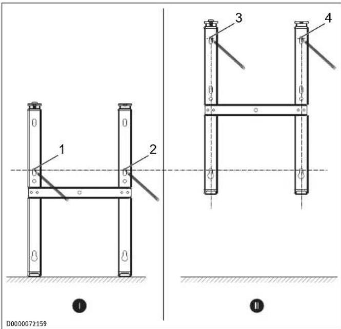
√ There are no electric cables or pipes in the drilling area.
▶ Mark out holes 1 and 2 for drilling.
▶ Lift up the wall mounting bracket so that its lower slots match up with the drill hole markings on the installation wall.
▶ Mark out holes 3 and 4 for drilling.
Drill the holes.
▶ Secure the wall mounting bracket with suitable fixing materials (screws, rawl plugs). Use the slots to compensate for any inaccuracies in the drill holes.
5.3 Installing the appliance
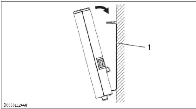
1 Wall mounting bracket
▶ Hook the appliance onto the bottom tabs of the wall mounting bracket by the slots in the back of the appliance.
▶ Place the appliance in an upright position.
▶ Push the appliance towards the supporting wall.
⇒ The appliance audibly snaps into place in the two upper springs on the wall mounting bracket.
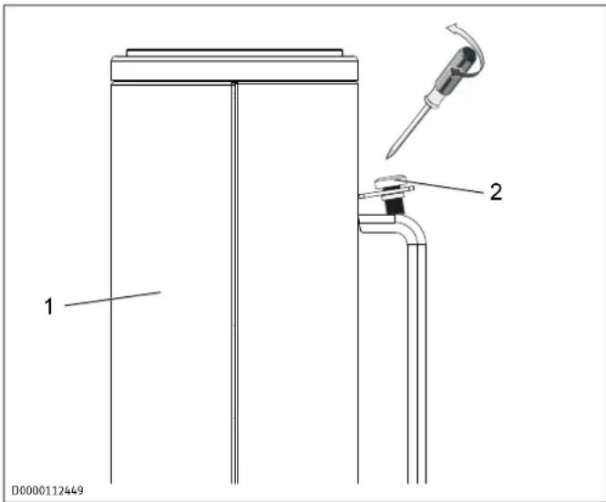
1 Appliance 2 Locking screw
▶ Secure the appliance against unintentional release using the supplied locking screw on the left-hand side of the wall mounting bracket.
5.4 Electrical connection
WARNING

Electrocution
Incorrect electrical connection and installation work may lead to serious injury through electrocution and to appliance damage.
Carry out all electrical connection and installation work in accordance with national and regional regulations.
In the case of a permanent connection, ensure that the appliance can be disconnected from the power supply by an isolator with at least 3 mm omnipolar contact separation.
▶ Please note that installing the appliance with a fixed power cable is not permissible.
▶ Only an authorised electrician is allowed to make the permanent connection to a junction box.
When connecting to an appliance junction box, guide the cable through a strain relief fitting.
▶ Connect the appliance to the earth conductor.
▶ Seal the trimmed cable ends again correctly with wire ferrules.
NOTICE

Property damage
If the appliance is not operated at the correct mains voltage, it will be damaged.
▶ Operate the appliance at the mains voltage stated on the type plate.
▶ Ensure the on-site supply cable has an adequate cross-section.

In a non-domestic environment and in case of particularly high demands on the appliance, such as permanent continuous operation, we recommend that the appliance is installed with a permanent connection to a junction box.
The appliance is delivered fully wired. The following electrical connections are permissible:
Connection to a standard safety socket with matching plug
▶ Ensure that the standard safety socket is easily accessible once the appliance has been installed.
Permanent connection to a junction box with earth conductor

Step-by-step guide
Video on permanent connection of the appliance

▶ Trim the power cable so it leads directly to the junction box.
▶ Ensure that, after trimming the power cable, the appliance can still be removed from the wall without a problem.
6 Commissioning (qualified contractors)
The appliance is ready for operation as soon as it has been fixed to the wall and plugged into the mains.
▶ Remove the protective film from the programming unit.

On initial start-up and after longer breaks in use, an odour may develop briefly after switching on.
▶ Switch on the appliance using the ON/OFF switch.
7 Operation

Support with operation
Video on how to operate the appli- ance

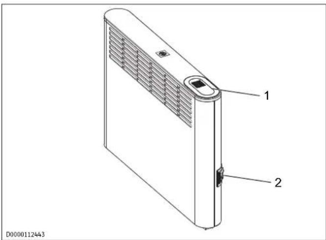
1 Programming unit 2 ON/OFF switch
7.1 Programming unit
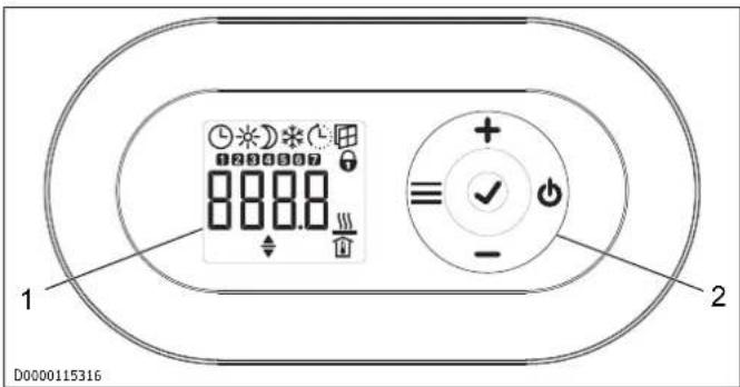
1 Display 2 Operating buttons
7.2 Operating buttons
| Button | Designation Description |
| (Y3H6) | "Standby" button Switch on the programming unit;Put programming unit and heating appliance into standby |
| √ | "OK" button Selection;Confirm settings |
| ≡ | "Menu" button Call up and exit menu |
| + | "+" button Call up menu items;Change settings |
| - | "-" button Call up menu items;Change settings |
7.3 Display
If no button is pressed for 20 seconds, the backlighting switches off.
▶ Press any button to switch the backlighting back on.
| Symbols | Description |
 | Time indication:Indication of the current time or a programmed start time |
| Time program activated:The appliance heats in accordance with the enabled time program. | |
 | Comfort mode:The appliance maintains the set comfort temperature.Default value: 21.0 °C. Use this setting for comfortable room temperatures when someone is present. |
 | Setback mode:The appliance maintains the selected setback temperature.Default value: 18.0 °C. Use this setting e.g. at night or when absent for several hours. |
 | Frost protection:The frost protection symbol is displayed if the room temperature is set to 7.0 °C.Use this setting to protect an unused room from frost damage. |
 | Adaptive start:With a time program activated, the heating appliance switching times are adjusted to ensure that the selected set room temperature is already reached by the programmed start time.Requirement: The "adaptive start" function is enabled (see chapter Standard menu [▶ 21]). |
 | Window-open detection:To avoid unnecessary energy consumption while airing the room, the appliance automatically switches to frost protection mode for one hour if a window is opened. The "Window-open detection" symbol flashes. After airing, frost protection mode can be terminated manually by pressing "+". The appliance then heats to the set room temperature again.Requirement: window-open detection is enabled (see chapter Standard menu [▶ 21]). |
 | Operating lock:To lock or unlock the operating buttons, press "+" and "-" simultaneously for 5 seconds. |
 | Heating enabled:The appliance is heating to maintain the set room temperature. |
 | Room temperature indication |
 | Editable parameter:The parameter shown can be changed using "+" and "-". |
 | Days of the week:1 = Monday, 2 = Tuesday ... 7 = Sunday |
7.4 Standby

NOTICE
Property damage
In standby mode, the appliance will not switch on the heating. There will be no frost protection.
▶ To switch on the programming unit, press "Standby".
⇒ The default display appears.
▶ To put the programming unit and the heating appliance into standby, press "Standby".
⇒ The display shows "----".
8 Settings
8.1 Default display
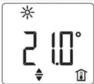
D0000072134
The default display is displayed continuously. If no user input is made for more than 20 seconds while in the menu, the appliance automatically switches to the standard display.
The default display shows the current set room temperature as well as the "Editable parameter" symbol. The "+" and "-" buttons can be used to change the set room temperature.
If the set room temperature corresponds to one of the values set for the comfort or setback temperature, the symbol for the corresponding operating mode (comfort mode, setback mode) appears in the menu bar.
The set room temperature can be changed manually when a time program is active. The new set room temperature is maintained until the next programmed switching point is reached.
8.2 Standard menu
▶ To call up the standard menu, press "Menu".
Menu items
| Display Description | |
| To select the day of the week and time:Days of the week: 1 = Monday to 7 = Sunday | |
| To set the comfort temperature:The comfort temperature must be set at least0.5 °C higher than the setback temperature. | |
| To set the setback temperature:The setback temperature must be set at least0.5 °C lower than the comfort temperature. | |
| To switch "Window-open detection" function onand off | |
| Select or deactivate (off) the time program (Pro1,Pro2, Pro3) | |
| To switch "Adaptive start" function on and off | |
Changing the menu item settings
▶ Call up the required menu item using "+" and "-"
▶ Press "OK".
→ The "Editable parameter" symbol appears.
▶ Change the menu item setting using "+" and "-"
▶ To save the setting, press "OK".
▶ To call up the standard menu, press "Menu".
⇒ The default display appears.
8.3 Configuration menu
Display Description
I1-I2 Actual values
Pro1-Pro3 Time programs
P1-P5 Parameter
Calling up actual values, programming time programs and setting parameters
▶ To access the configuration menu, press and hold the "Menu" button for about 3 seconds.
⇒ The actual value l1 is displayed.
▶ Use "+" and "-" to switch between the individual actual values, time programs and parameters.
▶ To exit the configuration menu, press "Menu".
→ The default display appears.
8.3.1 Actual values
| Dis-play | Description | Unit |
| I1 | Actual room temperature | [°C] I [°F] |
| I2 | Relative heating time(The counter can be reset via parameter P5) | [h] |

The counter for relative heating time (12) counts in full hours how long the appliance heats for. When the appliance is switched off, any heating phase of less than 60 minutes is not recorded.
8.3.2 Setting time programs (weekly timer)
Three time programs are available. Time programs Pro1 and Pro2 are pre-configured at the factory. Time program Pro3 can be set according to your individual requirements.
| Dis-play | Description |
| Pro1 | Time program "Daily"- Repeated: Monday to Sunday |
| Pro2 | Time program "Weekdays"- Repeated: Monday to Friday |
| Pro3 | Time program "User-defined"- up to 14 comfort phases, user-configurable |
▶ To use a time program, select the required time program in the standard menu (see chapter Standard menu [▶ 21]).
When setting the time programs, ensure the day of the week and the time are set correctly.

The following applies to all time programs (Pro1, Pro2, Pro3):
If the end time is later than 23:59 h, the end time will automatically be moved to the next day of the week. The comfort phase is maintained past midnight and will end on the next day at the set end time.
Time programs Pro1 and Pro2
With time programs Pro1 and Pro2, you can specify the comfort mode start and end times. During the selected period, the appliance heats to the set comfort temperature. Outside this specified period, the appliance operates in setback mode. This results in a comfort phase and a setback phase, which are repeated daily (Pro1) or on every working day (Pro2).
Theses phases are factory-set as follows:
- 08:00 h - 22:00 h: Comfort mode
- 22:00 h - 08:00 h: Setback mode

When time program Pro2 is enabled, the appliance operates only in setback mode at weekends.
To configure comfort phases in time programs Pro1 and Pro2:
In the configuration menu, call up the required time program using "+" and "-"
▶ Press "OK".
→ The start time for comfort mode is displayed.
▶ Use "+" and "-" to set the required start time.
▶ Press "OK".
⇒ The end time for comfort mode is displayed.
▶ Use "+" and "-" to set the required end time.
▶ To save the setting, press "OK".
Time program Pro3
You can use time program Pro3 to specify up to 14 separate comfort phases which are repeated weekly.
To configure a comfort phase in time program Pro3:
In the configuration menu, call up the time program Pro3 using "+" and "-"
▶ Press "OK".
⇒ The display shows "3---".
▶ Press "OK".
A day of the week or a group of days is displayed.
▶ Use "+" and "-" to select the required day or group of days.
▶ Press "OK".
→ The start time for comfort mode is displayed.
▶ Use "+" and "-" to set the required start time.
▶ Press "OK".
→ The end time for comfort mode is displayed.
▶ Use "+" and "-" to set the required end time.
▶ Press "OK".
⇒ Comfort phase "3-01" has been configured.
To configure a further comfort phase, use "+" and "-" in time program Pro3 to select display "3---". Proceed as describe above.
Resetting the time programs

Activating parameter P4 resets all time programs (Pro1, Pro2, Pro3) to the factory setting.
▶ To reset the selected comfort phases, activate parameter P4.
8.3.3 Parameter
| Display Description Options | |
| P1 Room temperature offset ± 3 °C / ± 5 °F | |
| P2 Time format 12 h | 24 h | |
| P3 Units for temperature indication °C | °F | |
| P4 Reset Time programs | on | off |
| P5 Reset relative heating time | on | off |
Changing a parameter value
▶ Call up the required parameter using "+" and "-"
▶ Press "OK".
→ The "Editable parameter" symbol appears.
▶ Select the required parameter value using "+" and "-"
▶ Press "OK" to save the selected value.
P1: Room temperature offset
Uneven temperature distribution in the room can result in a differential between the displayed actual temperature I1 and the room temperature you measure. To compensate for this differential, a room temperature offset of ±3 ^ can be set with parameter P1.
Example: The appliance shows I_1 = 21.0 ^ . You have measured a room temperature of 20.0 ^ . There is a differential of 1.0 ^ .
▶ To compensate for the differential, select an offset of P1 = -1.0.
P2: Time format
Parameter P2 allows you to specify whether the time is displayed in the 12 hour or 24 hour format.
P3: Units for temperature indication
Parameter P3 is used to specify whether the room temperature is displayed in degrees Celsius [°C] or Fahrenheit [°F].
P4: Reset time programs
Activating parameter P4 resets all Time programs to the factory setting.
P5: Reset relative heating time
Activating parameter P5 resets the counter for relative heating time (I2).
9 Cleaning (users)
NOTICE

Property damage
If moisture enters the appliance, the electronic components may be damaged.
▶ Never spray cleaning spray into the air slot.
▶ Ensure that no moisture can enter the appliance.
If a pale brownish discolouration appears on the appliance casing, wipe it off with a damp cloth.
▶ Clean the appliance when cold with ordinary cleaning products. Avoid abrasive or corrosive cleaning products.
10 Troubleshooting (users)
| Fault Possible cause | Remedy | |
| Room does not get warm enough. Ap- pliance does not get hot. | Temperature set too low on the appli- ance. | Check the selected room temperature. Adjust if necessary. |
| No power supply. Check position of the ON/OFF switch, RCD and fuse/MCB in your fuse box. | ||
| Room does not get warm enough al- though the appli- ance is hot. | Overheating. The high limit safety cut- out limits the heat- ing output. | Eliminate the cause (dirt or obstructions at the air intake or outlet). Observe the minimum clear- ances. |
| Heat demand of the room is higher than the appliance out- put. | Remedy heat losses (close windows and doors; avoid con- stant airing). | |
| The room gets too hot. | Appliance temperat- ure is set too high. | Check the selected room temperature. Adjust if necessary. |
| Detected room tem- perature does not match actual room temperature. | Avoid obstructions to air flow between appliance and in- door air. | |
| Window-open de- tection does not re- spond. | Appliance does not detect a pronounced temperature drop when airing. (Win- dow-open detection requires a previ- ously stable room temperature.) | After making set- tings on the appli- ance, wait a while until the room tem- perature has fully stabilised. |
| Avoid obstructions to air flow between appliance and in- door air. | ||
| Manually switch the appliance to standby while windows are open. | ||
| Window-open de- tection is not en- abled. | Switch on window- open detection in the standard menu. | |
| "Adaptive start" function does not work as required. | This function is only effective when a time program is act- ive. | Use the time pro- grams for optimised heating conveni- ence. |
| Severely fluctuating room temperature or the appliance learning procedure has not been com- pleted. | Wait a few days for the behaviour to stabilise. | |
| "Adaptive start" function is not en- abled. | Switch on the "Ad- aptive start" function in the standard menu. | |
| Fault Possible cause Remedy | ||
| The display shows "Err" or "E...". | Internal fault detected. | Notify a qualified contractor. |
▶ If you cannot remedy the fault, contact your qualified contractor.
▶ To facilitate and speed up your enquiry, please provide the qualified contractor with the number from the type plate.
11 Troubleshooting (qualified contractors)
To prevent hazards, the power cable must only be replaced (for example if damaged) by a qualified contractor authorised by the manufacturer, using an original spare part.
12 Shutting down the system
▶ Use the ON/OFF switch to switch the appliance off when not in use for longer periods (e.g. during the summer months).
All settings remain intact after switching off or after an interruption to the power supply. A power reserve in the appliance ensures that the day of the week and the time are saved for several hours.
If the appliance has been switched off for a longer time with a time program activated, you will be prompted to set the day and time after switching it back on. Until this setting is made, the appliance will operate in comfort mode.
13 Removal
▶ Isolate all poles of the appliance from the power supply.
▶ Undo and remove the locking screw from the wall mounting bracket.
▶ To release the appliance, push down the springs at the top of the wall mounting bracket.
▶ Tilt the appliance forwards.
▶ Lift the appliance off the bottom tabs on the wall mounting bracket.
▶ To remove the wall mounting bracket, undo and remove the fixing screws from it.
NOTICE

▶ If you need to disassemble the appliance for repair, follow the repair instructions for the appliance.
14 Specification
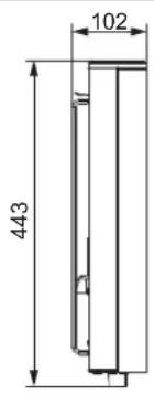
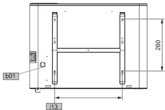
14.1 Dimensions and connections
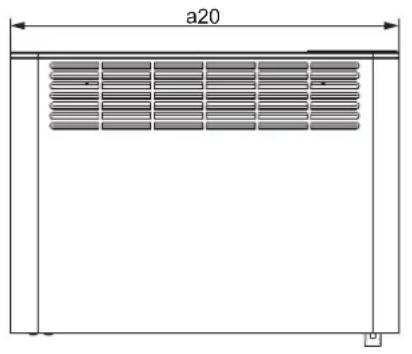
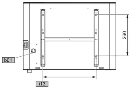
D0000112442
| CNS500PlusLCD | CNS750PlusLCD | CNS1000PlusLCD | CNS1500PlusLCD | CNS2000PlusLCD | CNS2500PlusLCD | CNS3000PlusLCD |
a20 Appliance Width mm 348 426 426 582 738 894 1050
b01 Entry electrical cables
i13 Wall mounting bracket Horizontal hole spacing mm 101 179 179 335 491 647 803
14.2 Energy consumption data
The product data complies with EU regulations relating to the directive on the ecodesign of energy related products (ErP).
Product information on electric local space heaters to regulation (EU) 2024/1103
| CNS 500 Plus LCD | CNS 750 Plus LCD | CNS 1000 Plus LCD | CNS 1500 Plus LCD | CNS 2000 Plus LCD | CNS 2500 Plus LCD | CNS 3000 Plus LCD | |
| 205853 | 205854 | 205855 | 205856 | 205857 | 205858 | 205859 | |
| Manufacturer STIEBE | STIEBE L EL-TRON | STIEBE L EL-TRON | STIEBE L EL-TRON | STIEBE L EL-TRON | STIEBE L EL-TRON | STIEBE L EL-TRON | |
| Heat output | |||||||
| Nominal heat output P_nom | kW 0.500 | 0.750 | 1.000 | 1.500 | 2.000 | 2.500 | 3.000 |
| Minimum heat output (indicative) P_min | kW 0.000 | 0.000 | 0.000 | 0.000 | 0.000 | 0.000 | 0.000 |
| Maximum continuous heat output P_max,c | kW 0.500 | 0.750 | 1.000 | 1.500 | 2.000 | 2.500 | 3.000 |
| Power consumption | |||||||
| In off-mode P_0 | W 0.00 | 0.00 | 0.00 | 0.00 | 0.00 | 0.00 | |
| In standby mode P_sm | W 0.12 | 0.12 | 0.12 | 0.12 | 0.12 | 0.12 | |
| In idle mode P_idle | W 0.12 | 0.12 | 0.12 | 0.12 | 0.12 | 0.12 | |
| In networked standby mode P_nsm | W | N/A | N/A | N/A | N/A | N/A | N/A |
| Standby mode with information or status display | x | x | x | x | x | x | |
| Seasonal energy efficiency in active mode _s,on | % 94.0 | 94.0 | 94.0 | 94.0 | 94.0 | 94.0 | |
| Type of heat output/room temperature control | |||||||
| Single stage heat output, no room temperature control | - | - | - | - | - | - | |
| Two or more manual stages, no room temperature control | - | - | - | - | - | - | |
| Mechanic thermostat room temperature control | - | - | - | - | - | - | |
| With electronic room temperature control | - | - | - | - | - | - | |
| With electronic room temperature control plus day timer | - | - | - | - | - | - | |
| With electronic room temperature control plus week timer | x | x | x | x | x | x | |
| Other control options | |||||||
| Room temperature control, with presence detection | - | - | - | - | - | - | |
| Room temperature control, with open window detection | x | x | x | x | x | x | |
| With distance control option | - | - | - | - | - | - | |
| With adaptive start control | x | x | x | x | x | x | |
| With working time limitation | - | - | - | - | - | - | |
| With black bulb sensor | - | - | - | - | - | - | |
| Self-learning | - | - | - | - | - | - | |
| Control accuracy | - | - | - | - | - | - | |
14.3 Data table
| CNS500PlusLCD | CNS750PlusLCD | CNS1000PlusLCD | CNS1500PlusLCD | CNS2000PlusLCD | CNS2500PlusLCD | CNS3000PlusLCD | |
| 205853 | 205854 | 205855 | 205856 | 205857 | 205858 | 205859 | |
| Electrical data | |||||||
| Connected load W 500 750 1000 1500 2000 2500 3000 | |||||||
| Power supply 1/N/ | 1/N/PE~230V | 1/N/PE~230V | 1/N/PE~230V | 1/N/PE~230V | 1/N/PE~230V | 1/N/PE~230V | |
| Rated current A 2.2 3.3 4.3 6.5 8.7 10.9 13.0 | |||||||
| Frequency Hz 50/- 50/- 50/- 50/- 50/- 50/- 50/- | |||||||
| Dimensions | |||||||
| Height mm 450 450 450 450 450 450 450 | |||||||
| Width mm 348 426 426 582 738 894 1050 | |||||||
| Depth mm 100 100 100 100 100 100 100 | |||||||
| Weights | |||||||
| Weight kg 4 4.9 4.9 6.3 7.8 9.5 10.9 | |||||||
| Versions | |||||||
| Frost protection setting | °C 7 7 7 7 7 7 7 | ||||||
| Version | Wallmoun-ted ap- pliance | Wallmoun-ted ap- pliance | Wallmoun-ted ap- pliance | Wallmoun-ted ap- pliance | Wallmoun-ted ap- pliance | Wallmoun-ted ap- pliance | Wallmoun-ted ap- pliance |
| IP rating | IP24 | IP24 | IP24 | IP24 | IP24 | IP24 | IP24 |
| Protection class | I | I | I | I | I | I | I |
| Colour | alpine white | alpine white | alpine white | alpine white | alpine white | alpine white | alpine white |
| Values | |||||||
| Setting range | °C | 5-30 | 5-30 | 5-30 | 5-30 | 5-30 | 5-30 |
15 Guarantee
The guarantee conditions of our German companies do not apply to appliances acquired outside of Germany. In countries where our subsidiaries sell our products a guarantee can only be issued by those subsidiaries. Such guarantee is only granted if the subsidiary has issued its own terms of guarantee. No other guarantee will be granted.
We shall not provide any guarantee for appliances acquired in countries where we have no subsidiary to sell our products. This will not affect warranties issued by any importers.
16 Environment and recycling
▶ Dispose of the appliances and materials after use in accordance with national regulations.

If a crossed-out waste bin is pictured on the appliance, take the appliance to your local waste and recycling centre or nearest retail take-back point for reuse and recycling.
This document is made of recyclable paper.
▶ Dispose of the document at the end of the appliance's life cycle in accordance with national regulations.
4.1 Fourniture.... 28
natural_image
Technical line drawing of a rectangular enclosure with horizontal dimensions labeled 'a20' (no text or symbols beyond the label)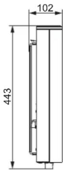
D0000112442
| CNS500PlusLCD | CNS750PlusLCD | CNS1000PlusLCD | CNS1500PlusLCD | CNS2000PlusLCD | CNS2500PlusLCD | CNS3000PlusLCD |
| CNS500PlusLCD | CNS750PlusLCD | CNS1000PlusLCD | CNS1500PlusLCD | CNS2000PlusLCD | CNS2500PlusLCD | CNS3000PlusLCD |
a20 Toestel Breedte mm 348 426 426 582 738 894 1050
b01 Doorvoer elektr.kabels
i13 Wandbevestiging Gatafstand horizontaal mm 101 179 179 335 491 647 803
| CNS500PlusLCD | CNS750PlusLCD | CNS1000PlusLCD | CNS1500PlusLCD | CNS2000PlusLCD | CNS2500PlusLCD | CNS3000PlusLCD |