USER MANUAL FXSQ15A2VEB DAIKIN
INSTALLATION AND OPERATION MANUAL

System air conditioners
Installation and operation manual VRV System air conditioners
Daikin Industries Czech Republic s.r.o.
01 (G) declares under its sole responsibility that the air conditioning models to which this declaration relates:
02 (B) erklaf auf seine allgemeine Verantwortung das die Modelle der Klimageräte für die dieser Erfahrung bestimm ist. 03 (C) definiert es an eine gewichtete variable, zu der variable nicht standardisierte variabeler Definition.
M (m) warkhard hisdi ene axisie ueantvortgelikhd de da amondioning unita wason dge warkring he
05 (E) declares bala su unica responsabilitad que los modeos de aire acondicionado a los cuales hace reference la de
06 (1) dichiarare sotso sua responsabilita che i condizionator modello a cui e rifita esta dichiarazione;
07 @8 5nKwE PE ANKOBOTIK Tng cUOuN on ta oVtA uau KIpaATIKUv CooKEuON Oa omOc AovpePoi n mopo
08 (P) declares so sua exclusiva responsabildte que os modeos de ar concionacion a que esta declaracao se refere:
FXSQ15A2VEB, FXSQ20A2VEB, FXSQ25A2VEB, FXS
FXSQ100A2VEB, FXSQ125A2VEB, FXSQ140A2VEB,
FXSQ15A2VEB, FXSQ20A2VEB, FXSQ25A2VEB, FXSQ32A2VEB, FXSQ40A2VEB, FXSQ50A2VEB, FXSQ63A2VEB, FXSQ80A2VEB,
| 01 | in conformità with the following standard(s) or other normative document(s), provided that these are used in accordance with our instructions: | 08
09
10
11
12
13
14
15
16
17
18
19
20
21
22
23
24
25
26
27
28
29
30
31
32
33
34
35
36
37
38
39
40
41
42
43
44
45
46
47
48
49
50
51
52
53
54
55
56
57
58
59
60
61
62
63
64
65
66
67
68
69
70
71
72
73
74
75
76
77
78
79
80
81
82
83
84
85
86
87
88
89
90
91
92
93
94
95
96
97
98
99
100
101
102
103
104
105
106
107
108
109
110
111
112
113
114
115
116
117
118
119
120
121
122
123
124
125
126
127
128
129
130
131
132
133
134
135
136
137
138
139
140
141
142
143
144
145
146
147
148
149
150
151
152
153
154
155
156
157
158
159
160
161
162
163
164
165
166
167
168
169
170
171
172
173
174
175
176
177
178
179
180
181
182
183
184
185
186
187
188
189
190
191
192
193
194
195
196
197
198
199
200
201
202
203
204
205
206
207
208
209
210
211
212
213
214
215
216
217
218
219
220
221
222
223
224
225
226
227
228
229
230
231
232
233
234
235
236
237
238
239
240
241
242
243
244
245
246
247
248
249
250
251
252
253
254
255
256
257
258
259
260
261
262
263
264
265
266
267
268
269
270
271
272
273
274
275
276
277
278
279
280
281
282
283
284
285
286
287
288
289
290
291
292
293
294
295
296
297
298
299
300
301
302
303
304
305
306
307
308
309
310
311
312
313
314
315
316
317
318
319
320
321
322
323
324
325
326
327
328
329
330
331
332
333
334
335
336
337
338
339
340
341
342
343
344
345
346
347
348
349
350
351
352
353
354
355
356
357
358
359
360
361
362
363
364
365
366
367
368
369
370
371
372
373
374
375
376
377
378
379
380
381
382
383
384
385
386
387
388
389
390
391
392
393
394
395
396
397
398
399
400
401
402
403
404
405
406
407
408
409
410
411
412
413
414
415
416
417
418
419
420
421
422
423
424
425
426
427
428
429
430
431
432
433
434
435
436
437
438
439
440
441
442
443
444
445
446
447
448
449
450
451
452
453
454
455
456
457
458
459
460
461
462
463
464
465
466
467
468
469
470
471
472
473
474
475
476
477
478
479
480
481
482
483
484
485
486
487
488
489
490
491
492
493
494
495
496
497
498
499
500
501
502
503
504
505
506
507
508
509
510
511
512
513
514
515
516
517
518
519
520
521
522
523
524
525
526
527
528
529
530
531
532
533
534
535
536
537
538
539
540
541
542
543
544
545
546
547
548
549
550
551
552
553
554
555
556
557
558
559
560
561
562
563
564
565
566
567
568
569
570
571
572
573
574
575
576
577
578
579
580
581
582
583
584
585
586
587
588
589
590
591
592
593
594
595
596
597
598
599
600
601
602
603
604
605
606
607
608
609
610
611
612
613
614
615
616
617
618
619
620
621
622
623
624
625
626
627
628
629
630
631
632
633
634
635
636
637
638
639
640
641
642
643
644
645
646
647
648
649
650
651
652
653
654
655
656
657
658
659
660
661
662
663
664
665
666
667
668
669
670
671
672
673
674
675
676
677
678
679
680
681
682
683
684
685
686
687
688
689
690
691
692
693
694
695
696
697
698
699
700
701
702
703
704
705
706
707
708
709
710
711
712
713
714
715
716
717
718
719
720
721
722
723
724
725
726
727
728
729
730
731
732
733
734
735
736
737
738
739
740
741
742
743
744
745
746
747
748
749
750
751
752
753
754
755
756
757
758
759
760
761
762
763
764
765
766
767
768
769
770
771
772
773
774
775
776
777
778
779
780
781
782
783
784
785
786
787
788
789
790
791
792
793
794
795
796
797
798
799
800
801
802
803
804
805
806
807
808
809
810
811
812
813
814
815
816
817
818
819
820
821
822
823
824
825
826
827
828
829
830
831
832
833
834
835
836
837
838
839
840
841
842
843
844
845
846
847
848
849
850
851
852
853
854
855
856
857
858
859
860
861
862
863
864
865
866
867
868
869
870
871
872
873
874
875
876
877
878
879
880
881
882
883
884
885
886
887
888
889
890
891
892
893
894
895
896
897
898
899
800
801
802
803
804
805
806
807
808
809
810
811
812
813
814
815
816
817
818
819
820
821
822
823
B |


DAIKIN INDUSTRIES CZECH REPUBLIC s.r.o.
U Nové Hospody 1/1155, 301 00 Plzen Skvrnany,
Czech Republic
Tetsuya Baba
Managing Director
Pilsen, 2nd of March 2015
Contents Page
一
Before installation. 1
Important information regarding the refrigerant used. 2
Selecting installation site. 2
Preparations before installation. 2
Indoor unit installation 3
Installing the duct 3
Refrigerant piping work 4
Drain piping work 5
Electric wiring work 6
Wiring example and how to set the remote controller 7
Wiring example 7
Field setting. 8
Installation of the decoration panel. 10
Test operation. 10
Maintenance. 10
Disposal requirements 11
Wiring diagram. 12

READ THESE INSTRUCTIONS CAREFULLY BEFORE INSTALLATION. KEEP THIS MANUAL IN A HANDY PLACE FOR FUTURE REFERENCE.
IMPROPER INSTALLATION OR ATTACHMENT OF EQUIPMENT OR ACCESSORIES COULD RESULT IN ELECTRIC SHOCK, SHORT-CIRCUIT, LEAKS, FIRE OR OTHER DAMAGE TO THE EQUIPMENT. BE SURE ONLY TO USE ACCESSORIES MADE BY DAIKIN WHICH ARE SPECIFICALLY DESIGNED FOR USE WITH THE EQUIPMENT AND HAVE THEM INSTALLED BY A PROFESSIONAL.
IF UNSURE OF INSTALLATION PROCEDURES OR USE, ALWAYS CONTACT YOUR DAIKIN DEALER FOR ADVICE AND INFORMATION.
The English text is the original instruction. Other languages are translations of the original instructions.

Installation must be done by a licensed technician. The choice of materials and installation must comply with the applicable national and international regulations.
Before installation
- Leave the unit inside its packaging until you reach the installation site. Where unpacking is unavoidable, use a sling of soft material or protective plates together with a rope when lifting, this to avoid damage or scratches to the unit.
When unpacking the unit or when moving the unit after unpacking, be sure to lift the unit by holding on to the hanger bracket without exerting any pressure on other parts, especially on refrigerant piping, drain piping and other resin parts.
Refer to the installation manual of the outdoor unit for items not described in this manual.
Caution concerning refrigerant series R410A:
The connectable outdoor units must be designed exclusively for R410A.
- Do not place objects in direct proximity of the outdoor unit and do not let leaves and other debris accumulate around the unit. Leaves are a hotbed for small animals which can enter the unit. Once in the unit, such animals can cause malfunctions, smoke or fire when making contact with electrical parts.
Precautions
Do not install or operate the unit in rooms mentioned below.
- Places with mineral oil, or filled with oil vapour or spray like in kitchens. (Plastic parts may deteriorate.)
- Where corrosive gas like sulphurous gas exists. (Copper tubing and brazed spots may corrode.)
- Where volatile flammable gas like thinner or gasoline is used.
- Where machines generating electromagnetic waves exist. (Control system may malfunction.)
-
Where the air contains high levels of salt such as air near the ocean and where voltage fluctuates a lot (e.g. in factories). Also in vehicles or vessels.
-
Do not install accessories on the casing directly. Drilling holes in the casing may damage electrical wires and consequently cause fire.
This appliance is not intended for use by persons, including children, with reduced physical, sensory or mental capabilities, or lack of experience and knowledge, unless they have been given supervision or instruction concerning use of the appliance by a person responsible for their safety.
Children should be supervised to ensure that they do not play with the appliance.
This appliance is intended to be used by expert or trained users in shops, in light industry and on farms, or for commercial use by lay persons.
Sound pressure level is less than 70dB(A).
Accessories
Check if the following accessories are included with your unit.
| Metal clamp
1 piece | Drain hose
1 piece | Washer for
hanging bracket
8 pieces | 1 2
Medium
sealing pad
2 pieces |
| Large sealing pad
1 piece | Insulation for
fitting
for liquid pipe
1 piece
for gas pipe
1 piece | Long sealing
2 pieces | Installation and
operation manual |
| Screws for duct flanges
1 set
40 pieces. | 4 tie wraps |
Screws for fixing panels are attached to the air inlet panel.
Optional accessories
There are two types of remote controllers: wired and wireless. Select a remote controller according to customer request and install in an appropriate place. Refer to catalogues and technical literature for selecting a suitable remote controller.
- When installing bottom suction: air inlet panel and canvas connection for the air inlet panel.
For the following items, take special care during construction and check after installation is finished
| Tick ✓ when checked | |
| ■ | Is the indoor unit fixed firmly?The unit may drop, vibrate or make noise. |
| ■ | Is the gas leak test finished?It may result in insufficient cooling or heating. |
| ■ | Is the unit fully insulated and checked for air leaks?Condensate water may drip. |
| ■ | Does drainage flow smoothly?Condensate water may drip. |
| ■ | Does the power supply voltage correspond to that shown on the name plate?The unit may malfunction or components may burn out. |
| ■ | Are wiring and piping correct?The unit may malfunction or components may burn out. |
| ■ | Is the unit safely grounded?Dangerous at electric leakage. |
| ■ | Is the wiring size according to specifications?The unit may malfunction or components may burn out. |
| ■ | Is nothing blocking the air outlet or inlet of either the indoor or outdoor units?It may result in insufficient cooling or heating. |
| ■ | Are refrigerant piping length and additional refrigerant charge noted down?The refrigerant charge in the system might not be clear. |
| ■ | Are the air filters fixed property (when installing with rear duct)?Maintenance of the air filters can be impossible. |
| ■ | Is the external static pressure set?It may result in insufficient cooling or heating. |
Notes to the installer
- Read this manual carefully to ensure correct installation. Be sure to instruct the customer how to properly operate the system and show him/her the enclosed operation manual.
Explain to the customer what system is installed on the site. Be sure to fill out the appropriate installation specifications in the chapter "What to do before operation" of the outdoor unit operation manual.
This product contains fluorinated greenhouse gases covered by the Kyoto Protocol.
Refrigerant type: R410A
GWP(1) value: 1975
(1) GWP = global warming potential
Periodical inspections for refrigerant leaks may be required depending on European or local legislation. Please contact your local dealer for more information.
Selecting installation site
1 Select an installation site where the following conditions are fulfilled and that meets your customer's approval.
- Where optimum air distribution can be ensured.
- Where nothing blocks air passage.
- Where condensate water can be properly drained.
- Where the false ceiling is not noticeably on an incline.
- Where sufficient clearance for maintenance and service can be ensured.
- Where there is no risk of flammable gas leaking.
- The equipment is not intended for use in a potentially explosive atmosphere.
- Where piping between indoor and outdoor units is possible within the allowable limit. (Refer to the installation manual of the outdoor unit.)
- Keep indoor unit, outdoor unit, power supply wiring and transmission wiring at least 1 meter away from televisions and radios. This is to prevent image interference and noise in those electrical appliances. (Noise may be generated depending on the conditions under which the electric wave is generated, even if 1 meter is kept.)
- When installing the wireless remote controller kit, the distance between wireless remote controller and indoor unit might be shorter if there are fluorescent lights who are electrically started in the room. The indoor unit must be installed as far as possible away from fluorescent lights.
- Do not place objects that are susceptible to moisture directly beneath the indoor or outdoor units. Under certain conditions, condensation on the main unit or refrigerant pipes, air filter dirt or drain blockage may cause dripping, resulting in fouling or failure of the object concerned.
2 Ensure that a protective guard is installed on air suction and air outlet side to prevent that the fan blades or heat exchanger be touched.
The protection must comply with relevant European and national regulations.
3 Use suspension bolts for installation. Check whether the ceiling is strong enough to support the weight of the indoor unit. If there is a risk, reinforce the ceiling before installing the unit.
1 Service space
2 Drain pipe
3 Power supply wiring port
4 Transmission wiring port
5 Maintenance drain outlet
6 Gas pipe
7 Liquid pipe
Preparations before installation
1 Relation of ceiling opening to unit and suspension bolt position. (See figure 5)
| Model A (mm) B (mm) |
| 15~32 550 588 |
| 40~50 700 738 |
| 63~80 1000 1038 |
| 100~125 1400 1438 |
1 Indoor unit
2 Pipe
3 Suspension bolt pitch (x4)
4 Suspension bolt pitch distance
For installation, choose one of the possibilities as listed further.
1 Ceiling surface
2 Ceiling opening
3 Service access panel (optional accessory)
4 Air filter
5 Air inlet duct
6 Duct service opening
7 Interchangeable plate
Installation with rear duct and duct service opening (See figure 6b)
Installation with rear duct, no duct service opening (See figure 6c)

Before installation of the unit (in case of installation with duct, but no duct service opening): modify the position of the air filters.
1 Remove the air filter(s) at the outside of the unit
2 Remove the interchangeable plate
3 Install the air filter(s) from the inside of the unit
4 Reinstall the interchangeable plate


NOTE
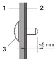
When installing an air inlet duct, select fixing screws that shall stick out maximum 5mm at the inside of the flange to protect the air filter from damage during maintenance of the filter.
1 Air inlet duct
2 Inside of the flange
3 Fixing screw
Mounting the air inlet panel with a canvas connection (See figure 7a)
1 Ceiling surface
2 Ceiling opening
3 Air inlet panel (Optional accessory)
4 Indoor unit (Back side)
5 Canvas connection for air inlet panel (Optional accessory)
Model A (mm)
| 15~32 610 |
| 40~50 760 |
| 63~80 1060 |
| 100~125 1460 |

NOTE
The unit can be used with bottom suction by replacing the interchangeable plate by the air filter holding plate.
1 Air filter holding plate with air filter(s)
2 Interchangeable plate

NOTE
For other installation than standard installation, contact your Daikin dealer for details.
2 The fan speed for this indoor unit is preset to provide standard external static pressure.
3 Install the suspension bolts.
(Use M10 size bolt for the suspension bolt.) Use anchors for existing ceilings, and a sunken insert, sunken anchors or other field supplied parts for new ceilings to reinforce the ceiling in order to bear the weight of the unit.
Installation example
(See figure 3)
1 Anchor
2 Ceiling slab
3 Long nut or turn-buckle
4 Suspension bolt
5 Indoor unit
All the above parts are field supplied.
For other installation than standard installation, contact your dealer for details.
Indoor unit installation
When installing optional accessories (except for the air inlet panel), read also the installation manual of the optional accessories. Depending on the field conditions, it may be easier to install optional accessories before the indoor unit is installed.
1 Install the indoor unit temporarily.
- Attach the hanger bracket to the suspension bolt. Be sure to fix it securely by using a nut and washer from the upper and lower sides of the hanger bracket. (See figure 4)
1 Nut (field supply)
2 Washer for hanger bracket (supplied with the unit)
3 Tighten (double nut)
2 Check if the unit is horizontally levelled.
- Do not install the unit tilted. The indoor unit is equipped with a built-in drain pump and float switch. (If the unit is tilted against condensate flow, the float switch may malfunction and cause water to drip.)
- Check if the unit is levelled at all four corners with a water level or a water-filled vinyl tube as shown in figure 9.
1 Water level
2 Vinyl tube
3 Tighten the upper nut.
Installing the duct
Connect the duct supplied in the field.
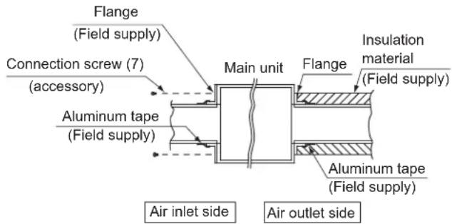
Air inlet side
- Attach the duct and intake-side flange (field supply).
- Connect the flange to the main unit with accessory screws (7).
- Wrap the intake-side flange and duct connection area with aluminum tape or something similar to prevent air escaping.

When attaching a duct to the intake side, be sure to attach an air filter inside the air passage on the intake side. (Use an air filter whose dust collecting efficiency is at least 50% in a gravimetric technique.)
The included filter is not used when the intake duct is attached.
Air outlet side
- Connect the duct according to the air inside of the outlet-side flange.
- Wrap the outlet-side flange and the duct connection area with aluminum tape or something similar to prevent air escaping

- Be sure to insulate the duct to prevent condensation from forming. (Material: glass wool or polyethylene foam, 25mm thick)
- Use electric insulation between the duct and the wall when using metal ducts to pass metal laths of the net or fence shape or metal plating into wooden buildings.
- Be sure to explain about the way of maintaining and cleaning local procurements (air filter, grille (both air outlet and suction grille), etc.) to your customer.
Refrigerant piping work
For refrigerant piping of outdoor unit, refer to the installation manual supplied with the outdoor unit.
Before rigging tubes, check which type of refrigerant is used.

Installation shall be done by a licensed refrigeration technician, the choice of materials and installation shall comply with the applicable national and international codes. In Europe, EN378 is the applicable standard that shall be used.
Use a pipe cutter and flare suitable for the used refrigerant.
To prevent dust, moisture or other foreign matter from infiltrating the tube, either pinch the end, or cover it with tape.
Use copper alloy seamless pipes (ISO 1337).
The outdoor unit is charged with refrigerant.
To prevent water leakage, execute heat insulation work completely on both sides of the gas and liquid piping. When using a heat pump, the temperature of the gas piping can reach up to approximately 120°C , use insulation which is sufficiently heat resistant.
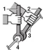
- Be sure to use both a spanner and torque wrench together when connecting or disconnecting pipes to/from the unit.
1 Torque wrench
2 Spanner
3 Piping union
4 Flare nut
- Do not mix anything other than the specified refrigerant, such as air, etc..., inside the refrigerant circuit.
Use annealed material only for flare connections.
Refer to Table 1 for the dimensions of flare nut spaces and the appropriate tightening torque. (Overtightening may damage the flare and cause leaks.)
Table 1
| Pipe gauge (mm) | Tightening torque (N·m) | Flare dimension A (mm) | Flare shape |
| Ø6.4 15~17 | 8.7~9.1 | | 50°2 |
| Ø9.5 33~39 | 12.8~13.2 | |
| Ø12.7 50~60 | 16.2~16.6 | |
| Ø15.9 63~75 | 19.3~19.7 | |
When connecting the flare nut, coat the flare inner surface with ether oil or ester oil and initially tighten 3 or 4 turns by hand before tightening firmly.

If the refrigerant gas leaks during the work, ventilate the area. A toxic gas is emitted by the refrigerant gas being exposed to a fire.
Make sure there is no refrigerant gas leak. A toxic gas may be released by the refrigerant gas leaking indoor and being exposed to flames from an area heater, cooking stove, etc.
Finally, insulate as shown in the figures below.
Piping insulation procedure
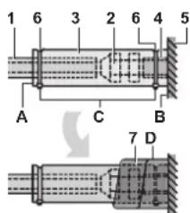
Gas piping Liquid piph
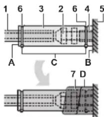
1 Piping insulation material (field supply)
2 Flare nut connection
3 Insulation for fitting (delivered with the unit)
4 Piping insulation material (main unit)
5 Main unit
6 Clamp (field supply)
7 Medium 1 sealing pad for gas piping (delivered with the unit) Medium 2 sealing pad for liquid piping (delivered with the unit)
A Turn seams up
B Attach to base
C Tighten the part other than the piping insulation material
D Wrap over from the base of the unit to the top of the flare nut connection

For local insulation, be sure to insulate local piping all the way into the pipe connections inside the unit.
Exposed piping may cause condensation or may cause burns when touched.
Cautions for brazing
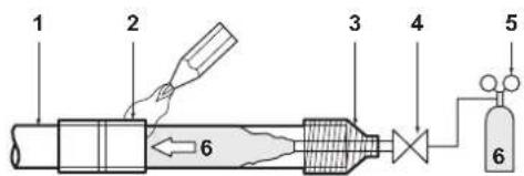
- Be sure to carry out a nitrogen blow when brazing. Brazing without carrying out nitrogen replacement or releasing nitrogen into the piping will create large quantities of oxidized film on the inside of the pipes, adversely affecting valves and compressors in the refrigerating system and preventing normal operation.
When brazing while inserting nitrogen into the piping, nitrogen must be set to 0.02MPa with a pressure-reducing valve (=just enough so that it can be felt on the skin).

1 Refrigerant piping
2 Part to be brazed
3 Taping
4 Hands valve
5 Pressure-reducing valve
6 Nitrogen
Drain piping work
Installation of drain piping
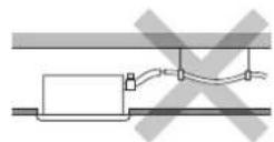
Install the drain piping as shown in the figure and take measures against condensation. Improperly rigged piping could lead to leaks and eventually wet furniture and belongings.
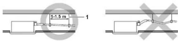
1 Hanging bar
Install the drain pipes.
- Keep piping as short as possible and slope it downwards at a gradient of at least 1/100 so that air may not remain trapped inside the pipe.
- Keep pipe size equal to or greater than that of the connecting pipe (vinyl pipe of 25mm nominal diameter and 32mm outer diameter).
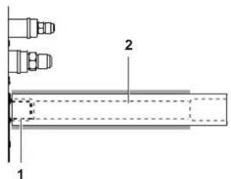
- Push the supplied drain hose as far as possible over the drain socket.

1 Drain socket (attached to the unit)
2 Drain hose (supplied with the unit)
- Tighten the metal clamp until the screw head is less than 4mm from the metal clamp part as indicated in the illustration.

1 Drain socket (attached to the unit)
2 Drain hose (supplied with the unit)
3 Metal clamp (supplied with the unit)
4 Large sealing pad (supplied with the unit)
5 Drain piping (field supply)
- Wrap the supplied large sealing pad over the metal clamp and drain hose to insulate and fix it with clamps.
- Insulate the complete drain piping inside the building (field supply).
- If the drain hose cannot be sufficiently set on a slope, fit the hose with drain raising piping (field supply).
How to perform drain piping
(See figure 10)
1 Ceiling slab
2 Hanger bracket
3 Adjustable range
4 Drain raising pipe
5 Drain hose (supplied with the unit)
6 Clamp metal (supplied with the unit)
1 Connect the drain hose to the drain raising pipes, and insulate them.
2 Connect the drain hose to the drain outlet on the indoor unit, and tighten it with the clamp.
| Installation A (mm) |
| Rear suction installation 231 |
| When canvas duct is installed 350-530 |
| When air inlet panel is directly installed | 231 |
Precautions
- Install the drain raising pipes at a height of less than 625mm
- Install the drain raising pipes at a right angle to the indoor unit and no more than 300mm from the unit.
- To prevent air bubbles, install the drain hose level or slightly tilted up (≤75 mm).
- The drain pump mounted in this unit is the high lift type. The characteristic of this pump is that the higher the pump is the lower the drainage sound becomes. Therefore a drain pump height of 300mm is recommended.
NOTE

The incline of attached drain hose should be 75mm or less so that the drain socket does not have to withstand additional force.
To ensure a downward slope of 1:100, install hanging bars every 1 to 1.5m
When unifying multiple drain pipes, install the pipes as shown in figure 11. Select converging drain pipes whose gauge is suitable for the operating capacity of the unit.
1 T-joint converging drain pipes
Testing of drain piping
After piping work is finished, check if drainage flows smoothly.
- Add approximately 1 l of water gradually through the air discharge outlet. Check for water leaks.
Method of adding water. See figure 8.
1 Water inlet
2 Portable pump
3 Water inlet cover
4 Bucket (adding water through water inlet)
5 Drain outlet for maintenance (with rubber drain plug)
6 Refrigerant pipes

Caution for drain socket
Do not remove the drain pipe plug. Water might leak out.
The drain outlet is only used to discharge water if the drain pump is not used or before maintenance. Gently put in and out the drain plug. Excessive force may deform the drain socket of the drain pan.
Pulling out the plug
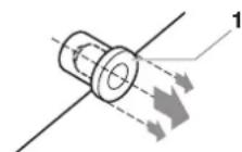
1 Drain plug
Do not wiggle the plug up and down
Pushing in the plug
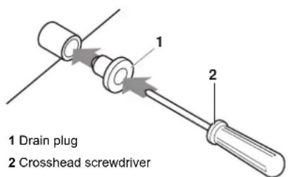
Set the plug and push it by using a crosshead screwdriver
First perform electric wiring work as instructed in "Electric wiring work" on page 6 and how to set the remote controller as explained in "Wiring example and how to set the remote controller" on page 7.
When electric wiring work is finished
Check drainage flow during COOL running, explained in "Test operation" on page 10.
When electric wiring work is not finished
Remove the switch box cover and connect the single-phase power supply and the remote controller to the terminals. (Refer to "Electric wiring work" on page 6 for switch box attachment/detachment.) (Refer to figure 12 and figure 14)
1 Switch box cover
2 Transmission wiring port
3 Power supply wiring port
4 Wiring diagram
5 Switch box
6 Plastic clamp
7 Remote controller wiring
8 Terminal board for unit transmission wiring
9 Power supply wiring
10 Indoor PC board 1
11 Power supply terminal board
12 Transmission wiring between units
13 Indoor PC board 2
14 Long sealing
15 Wiring
Next, press the inspection/test operation button the remote controller. The unit will engage the test operation mode. Press the operation mode selector button until selecting fan operation
- Then, press the on/off button the indoor unit fan and drain pump will start up. Check that the water has drained from the unit. Press go back to the first mode.
Electric wiring work
General instructions
All field wiring and components must be installed by a licensed electrician and must comply with relevant European and national regulations.
Use copper wire only.
- Follow the "Wiring diagram" attached to the unit body to wire the outdoor unit, indoor units and the remote controller. For details on hooking up the remote controller, refer to the "Installation manual of the remote controller".
All wiring must be performed by an authorized electrician.
- Attach the earth leakage circuit breaker and fuse to the power supply line.
A main switch or other means for disconnection, having a contact separation in all poles, must be incorporated in the fixed wiring in accordance with relevant local and national legislation. Note that the operation will restart automatically if the main power supply is turned off and then turned back on again.
Refer to the installation manual delivered with the outdoor unit for the size of power supply electric wire connected to the outdoor unit, the capacity of the earth leakage breaker and fuse and for wiring instructions.
■ Be sure to ground the air conditioner.
Do not connect the ground wire to:
- gas pipes: might cause explosions or fire if gas leaks.
- telephone ground wires or lightning rods: might cause abnormally high electric potential in the ground during lightning storms.
- plumbing pipes: no grounding effect if hard vinyl piping is used.
Make sure that earth wire between the pull relief and terminal is longer than other wires.
- Be sure that the shape of the power supply cable and any other cable, before entering unit, should be as shown in this figure.
All cables entering the unit should be fixed by tie wraps (accessory).
Use long sealing (accesory) to block entrance of switch box as shown in figure 12.

Electrical characteristics
| Model | Hz | Volts | Voltage range | Power supply |
| MCA | MFA |
| 15 | 50/60 | 220-240/220 | ±10% | 0.4 | 16 A |
| 20 | 0.4 |
| 25 | 0.4 |
| 32 | 0.4 |
| 40 | 0.8 |
| 50 | 0.8 |
| 63 | 0.9 |
| 80 | 1.0 |
| 100 | 1.5 |
| 125 | 2.0 |
MCA: Min. circuit Amps (A)
MFA: Max. Fuse Amps (A)

For details, refer to "Electrical data" in the technical data book.
Specifications for field supplied fuses and wire
| Power supply wiring
Model Field fuses Wire Size |
| 15~125 16 A H05VV-U3G Local codes |
| Model Wire Size |
| 15~125 Sheathed wire (2) | 0.75-1.25 mm² |
NOTE
For details, refer to "Wiring example" on page 7.

Allowable length of transmission wiring between indoor and outdoor units, and between the indoor unit and the remote controller is as follows:
- Outdoor unit - indoor unit: max. 1000 m (total wiring length: 2000 m)
- Indoor unit - remote controller: max 500 m
Wiring example and how to set the remote controller
How to connect wiring
Remove the switch box cover as shown in figure 12, and make the connections.
1 Switch box cover
2 Switch box low voltage wiring inlet
3 Switch box high voltage wiring inlet
4 Wiring diagram
5 Switch box
Precautions
-
Observe the notes mentioned below when wiring to the power supply terminal board.
-
Use a round crimp-style terminal for insulation sleeve for connection to the terminal block for wiring the units. When none are available, follow the instructions below.

1 Round crimp-style terminal
2 Attach insulation sleeve
3 Wiring
- Do not connect wires of different gauge to the same power supply terminal. (Looseness in the connection may cause overheating.)
- When connecting wires of the same gauge, connect them according to the figure.


Use the specified electric wire. Connect the wire securely to the terminal. Lock the wire down without applying excessive force to the terminal. Use torques according to the table below.
Tightening torque (N· m)
| Terminal block for remote controller | 0.79~0.97 |
| Terminal block for power supply | 1.18~1.44 |
- When attaching the control box lid, make sure not to pinch any wires.
-
After all wiring connections are done, fill in any gaps in the casing wiring holes with putty or insulation material (field supply) thus to prevent small animals or dirt from entering the unit from outside and causing short circuits in the control box.
-
Do not connect wires of different gauge to the same grounding terminal. Looseness in the connection may deteriorate the protection.
- Remote controller cords and wires connecting the units should be located at least 50 mm away from power supply wiring. Not following this guideline may result in malfunction due to electrical noise.
- For the remote controller wiring, refer to the "Installation manual of the remote controller" supplied with the remote controller.
NOTE

The customer has the ability to select the remote controller thermistor.
- Never connect the power supply wiring to the terminal board for transmission wiring. This mistake could damage the entire system.
- Use only specified wires and tightly connect wires to the terminals. Be careful that wires do not place external stress on the terminals. Keep wiring in neat order so that they do not obstruct other equipment such as popping open the switch box cover. Make sure the cover closes tight. Incomplete connections could result in overheating, and in the worse case, electric shock or fire.
Keep total current of crossover wiring between indoor units less than 12 A. Branch the line outside the terminal block of the unit in accordance with the electrical equipment standards, when using two power wiring of a gauge greater than 2mm2 (Ø1.6).
The branch must be sheathed in order to provide an equal or greater degree of insulation as power supply wiring itself.
Wiring example
Fit the power supply wiring of each unit with a switch and fuse as shown in figure 16.
1 Power supply
2 Main switch
3 Power supply wiring
4 Transmission wiring
5 Switc
6 Fuse
7 BS unit REYQ only
8 Indoor unit
9 Remote controller
Complete system example (3 systems)
When using 1 remote controller for 1 indoor unit (Normal operation) (See figure 15)
For group control or use with 2 remote controllers (See figure 17)
When including BS unit (See figure 13)
1 Outdoor unit
2 Indoor unit
3 Remote controller (optional accessories)
4 Most downstream indoor unit
5 For use with 2 remote controllers
6 BS unit

It is not necessary to designate an indoor unit address when using group control. The address is automatically set when the power is activated.
Precautions
- A single switch can be used to supply power to units on the same system. However, branch switches and branch circuit breakers must be selected carefully.
- For a group control remote controller, choose the remote controller that suits the indoor unit which has the most functions.
- All transmission wiring except for the remote controller wiring is polarized and must match the terminal symbol.
- In case of group control, perform the remote controller wiring to the master unit when connecting to the simultaneous operation system (wiring to the slave unit is unnecessary).
- When controlling the simultaneous operation system with 2 remote controllers, connect it to the master unit (wiring to the slave unit is unnecessary).
- Be sure to connect the wiring to the master unit when combining with a simultaneous operating multi-type in group control.
- Do not ground the equipment on gas pipes, water pipes, lightning rods or crossground with telephones. Improper grounding could result in electric shock.
Field setting
Field setting must be made on the remote controller in function of the installation condition.
Setting can be made by changing the "Mode number", "First code No." and "Second code No".
For setting and operation, refer to the "Field settings" in the installation manual of the remote controller.
Summary of field settings
| Mode No.(Note 1) | First code No. | Description of setting | Second code No. (Note 2) |
| 01 02 03 | | |
| 10(20) | 0 | Filter contamination - Heavy/Light = Setting to define time between 2 filter cleaning display indications. (When contamination is high, setting can be changed to half the time inbetween 2 filter cleaning display indications.) | Ultra-long-life filter | Light | ±10,000 hrs. | ±5,000 hrs. | | |
| Long-life filter | ±2,500 hrs. | ±250 hrs. |
| Standard filter | ±200 hrs. ±100 hrs. |
| 2 | Thermostat sensor selection | Use both the unit sensor (or remote sensor if installed) AND the remote controller sensor. (See note 5+6) | Use unit sensor only (or remote sensor if installed). (See note 5+6) | Use remote controller sensor only. (See note 5+6) | |
| 3 | Setting for display of time between 2 filter cleaning display indications | Display Do not d | dysplay — — | | |
| 6 | Thermostat sensor in group control | Use unit sensor only (or remote sensor if installed). (See note 6) | Use both the unit senor (or remote sensor if installed) AND the remote controller sensor. (See note 4+5+6) | | |
| 12(22) | 0 | Output signal X1-X2 of the optional KRP1B PCB kit | Thermostat-on + compressor run | — Operation | | Mal-function |
| 1 | ON/OFF input from outside (T1/T2 input) = Setting when forced ON/OFF is to be operated from outside. | Forced OFF | ON/OFF operation | | |
| 3 | Fan setting during thermostat OFF at heating operation | LL Sat speed | | OFF (See note 3) | |
| 4 | Differential automatic changeover | 0°C 1°C 2°C | | | 3°C (See note 7) |
| 5 | Auto_restart after power failure | Disabled Enabled | — — | | |
| 9 | Fixed cool/heat master | Disabled | Enabled | | |
| 15(25) | 3 | Drain pump operation + humidifier interlock | Equipped | Not equipped | | |
Note 1: Setting is carried out in the group mode, however, if the mode number inside parentheses is selected, indoor units can also be set individually.
Note 2: Factory settings of the Second code No. are marked in grey backgrounds.
Note 3: Only use in combination with optional remote sensor or when setting 10-2-03 is used.
Note 4: If group control is selected and remote control sensor is to be used, then set 10-6-02 & 10-2-03.
Note 5: If setting 10-6-02 + 10-2-01 or 10-2-02 or 10-2-03 are set at the same time, then setting 10-2-01, 10-2-02 or 10-2-03 have priority.
Note 6: If setting 10-6-01 + 10-2-01 or 10-2-02 or 10-2-03 are set at the same time, then setting for group connection, 10-6-01 has priority and for individual connection, 10-2-01, 10-2-02 or 10-2-03 have priority.
Note 7: More settings for Differential automatic change over temperatures are:
Second code No. 05 4°C
06 5°C
07 6°C
08 7°C
External static pressure settings
Settings for external static pressure can be achieved in 2 ways:
Using the airflow automatic adjustment function
Airflow automatic adjustment is the volume of blow-off air that has been automatically adjusted to the rated quantity.
1 Make sure the test run is done with a dry coil.
If the coil is not dry, run the unit for 2 hours with fan only to dry the coil.
2 Check if the power supply wiring to the air conditioning unit is completed along with the duct installation.
If a closing damper is installed in the air conditioning unit, make sure that it is open.
Also check if the air filter is properly attached into the air passage on the air suction side of the air conditioning unit.
3 If there is more than one air inlet and outlet, adjust the dampers so that the airflow rate of each air inlet and outlet is conform with the designed airflow rate.
Make sure the air conditioning unit is in fan operation mode. Press and set the airflow adjustment button on the remote controller to change the airflow rate to H or L.
4 Setting the airflow automatic adjustment settings.
When the air conditioning unit is running in fan operation mode perform the next steps:
- stop the air conditioning unit,
- go to field setting mode,
- select mode No. 21 (or 11 in case of group setting),
- set the first code No. to "7",
- set the second code No. to "03".
Return to normal operating mode after setting these settings and press the ON/OFF operation button. The operation lamp will light up and the air conditioning unit will start the fan operation for airflow automatic adjustment.

Do not adjust the dampers during fan operation for airflow automatic adjustment.
After 1 to 8 minutes, the air conditioning unit stops operating automatically when the fan operation for airflow automatic adjustment has been carried out, the operation lamp will be off.
| Mode
No. | First
code No. | Second
code No. | Setting content |
| 11 (21) 7 | | 01 Airflow adjustment is OFF |
| 02 Completion of airflow adjustment |
| 03 Start of airflow adjustment |
5 When the air conditioning unit has stopped, check on an indoor unit if the second code No. of mode No. 21 is set to "02".
If the air conditioning unit does not stop operating or the second code No. is not "02", repeat step 4.
If the outdoor unit is not turned on, the display on the remote controller will show "UH" or "UH" (refer to "Test operation" on page 10). However, you can continue setting this function because these messages are only applicable to outdoor units.
After setting this function, be sure to turn on the outdoor unit before performing the test operation on the outdoor unit.
If any other error display occurs on the display of the remote controller, refer to "Test operation" on page 10 and the operation manual of the outdoor unit. Check the defective point.

If the external static pressure higher than 100Pa do not use airflow automatic adjustment function.
If there is no change after airflow adjustment in the ventilation paths, be sure to perform setting the airflow automatic adjustment again.
- Contact your dealer if there is no change after performing airflow adjustment in the ventilation paths, after performing the test operation of the outdoor unit or when the air conditioning unit is moved to another location.
If booster fans, an outdoor air processing unit or HRV via duct are used, do not use airflow automatic adjustment control with a remote controller.
If the ventilation paths have been changed, perform the setting of the airflow automatic adjustment again as described above from step 3 onwards.
Using the remote controller
Check on an indoor unit if the second code of mode No. 21 is set to "01" (= factory setting). Change the second code according to the external static pressure of the duct to be connected as shown in table 2.

The second code No. is set to "01" by default.
Table2
| Mode No. | 1st code No. | 2nd code No. | External static pressure (Pa) |
| FXSQ |
| 15 20 | 25 32 | 40 | 50 | 63 | 80 | 100 | 125 | | |
| 13(23) | 6 | 01 | 30 | 30 | 30 | 30 | 30 | 40 | 40 | 50 | | |
| 0 | 2 | - | - | - | - | - | - | - | - | - |
| 03 | 30 | 30 | 30 | 30 | 30 | - | - | - | | |
| 04 | 40 | 40 | 40 | 40 | 40 | 40 | 40 | - | | |
| 05 | 50 | 50 | 50 | 50 | 50 | 50 | 50 | | | |
| 06 | 60 | 60 | 60 | 60 | 60 | 60 | 60 | 50 | | |
| 07 | 70 | 70 | 70 | 70 | 70 | 70 | 70 | 70 | | |
| 08 | 80 | 80 | 80 | 80 | 80 | 80 | 80 | 80 | | |
| 09 | 90 | 90 | 90 | 90 | 90 | 90 | 90 | 90 | | |
| 10 | 100 | 100 | 100 | 100 | 100 | 100 | 100 | 100 | 100 | 100 |
| 11 | 110 | 110 | 110 | 110 | 110 | 110 | 110 | 110 | 110 | 110 |
| 12 | 120 | 120 | 120 | 120 | 120 | 120 | 120 | 120 | 120 | 120 |
| 13 | 130 | 130 | 130 | 130 | 130 | 130 | 130 | 130 | 130 | 130 |
| 14 | 140 | 140 | 140 | 140 | 140 | 140 | 140 | 140 | 140 | 140 |
| 15 | 150 | 150 | 150 | 150 | 150 | 150 | 150 | 150 | 150 | 150 |
Control by 2 Remote Controllers (Controlling 1 indoor unit by 2 remote controllers)
When using 2 remote controllers, one must be set to "MAIN" and the other to "SUB".
MAIN/SUB CHANGEOVER
Insert a wedge-head screwdriver into the recess between the upper and lower part of the remote controller and, working from the 2 positions, pry off the upper part. (See figure 18) (The remote controller PC board is attached to the upper part of the remote controller.)
Turn the main/sub changeover switch on one of the two remote controller PC boards to "S". (See figure 19) (Leave the switch of the other remote controller set to "M".)
1 Remote controller PC board
2 Factory setting
3 Only one remote controller needs to be changed
Computerised control (forced off and on/off operation)
1 Wire specifications and how to perform wiring
- Connect input from outside to terminals T1 and T2 of the terminal board (remote controller to transmission wiring).
| Wire specification Sheathed vinyl cord or cable (2 wire) |
| Gauge | 0.75-1.25 mm² |
| Length Max. 100 m | |
| External terminal Contact that can ensure the minimum applicable load of 15 V DC, 10 mA |
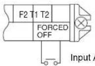
2 Actuation
- The following table explains "forced off" and "on/off operations" in response to input A.
| Forced off on/off operation |
| Input "on" stops operation | input off → on: turns on the unit (impossible by remote controllers) |
| Input "off" enables control | input on → off: turns off the unit by remote controller |
3 How to select forced off and on/off operation
- Turn the power on and then use the remote controller to select operation.
- Set the remote controller to the field set mode. For details, refer to the chapter "How to set in the field", in the remote controller manual.
- When in the field set mode, select mode No. 12, then set the first code No. to "1". Then set second code (position) No. to "01" for forced off and to "02" for on/off operation. (forced off at factory set.) (See figure 20)
1 Second code No.
2 Mode No.
3 First code No.
4 Field set mode
Centralized control
For centralized control, it is necessary to designate the group No. For details, refer to the manual of each optional controller for centralized control.
Installation of the decoration panel
Refer to the installation manual attached to the decoration panel.
After installing the decoration panel, ensure that there is no space between the unit body and decoration panel.
Test operation
Refer to the installation manual of the outdoor unit.
The operation lamp of the remote controller will flash when an error occurs. Check the error code on the liquid crystal display to identify the trouble.
| Error code Meaning |
| R8Error in | power supply to indoor unit |
| C1 | Transmission error between fan driver PCB and controller PCB of the indoor unit |
| C6 | Improper combination of fan driver PCB of the indoor unit or setting failure in control PCB type |
| U3Test operation of the indoor unit has not been finished |
If any of the items in following table are displayed on the remote controller, there may be a problem with the wiring or power, so check the wiring again.
| Error code Meaning |
| A | There is a short circuit at the forced off terminals (T1, T2) |
| UH or UH | - The power on the outdoor unit is off
- The outdoor unit has not been wired for power supply
- Incorrect transmission of forced off wiring |
| no display | - The power on the indoor unit is off
- The indoor unit has not been wired for power supply
- Incorrect transmission wiring, forced off wiring or remote controller wiring |
Maintenance

Caution
Only a qualified service person is allowed to perform maintenance.
Before obtaining access to terminal devices, all power supply circuits must be interrupted.
Do not use water or air of 50°C or higher for cleaning air filters and outside panels.
When cleaning the heat exchanger, be sure to remove the switchbox, fan motor, auxiliary electric heater and drain pump. Water or detergent may deteriorate the insulation of electronic components and result in burnout of these components.
If the main power supply is turned off during operation, operation will restart automatically after the power turns back on again.
How to clean the air filter
Clean the air filter when the display shows "TIME TO CLEAN AIR FILTER).
Increase the frequency of cleaning if the unit is installed in a room where the air is extremely contaminated.
If the dirt becomes impossible to clean, change the air filter. (Air filter for exchange is optional.)
1 Open the suction grille. (Only for bottom suction.)
Slide both knobs simultaneously as shown and then pull them downward.

If chains are present, unhook the chains.

2 Remove the air filters.
Remove the air filters by pulling their cloth upward (rear suction) or backward (bottom suction).
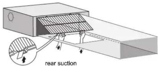

3 Clean the air filter.
Use vacuum cleaner (A) or wash the air filter with water (B).
(A) Using a vacuum cleaner
(B) Washing with water
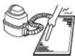

When the air filter is very dirty, use soft brush and neutral detergent.
Remove water and dry in the shade.
4 Fix the air filter.


Align the two hanger brackets and push the two clips in their place (pull the cloth if necessary).
Confirm that four hangers are fixed.
5 Shut the air inlet grille. (Only for bottom suction.)
Refer to item no. 1.
6 After turning on the power, press FILTER SIGN RESET button.
The "TIME TO CLEAN AIR FILTER" display is turned off.
How to clean air outlet and outside panels
Clean with soft cloth.
When it is difficult to remove stains, use water of neutral detergent.
Clean the air inlet grille when it is shut.
NOTE
Do not use gasoline, benzene, thinner, polishing powder, liquid insecticide. It may cause discolouring or warping.
Do not let the indoor unit get wet. It may cause an electric shock or a fire.
Start up after a long stop
Confirm the following:
Check that the air inlet and outlet are not blocked. Remove any obstacle.
Check if the earth is connected.
Clean the air filter and outside panels.
After cleaning the air filter, make sure to attach it.
Turn on the main power supply switch.
The control panel display lights when the power is turned on.
To protect the unit, turn on the main power switch at least 6 hours before operation.
What to do when stopping the system for a long period
Turn on FAN OPERATION for half a day and dry the unit.
Refer to the operation manual of the outdoor unit.
Cut off the power supply.
When the main power switch is turned on, some wattage is being consumed even if the system is not operating.
The remote controller display is turned off when the main power switch is turned off.
Disposal requirements
Dismantling of the unit, treatment of the refrigerant, of oil and of other parts must be done in accordance with relevant local and national legislation.
Wiring diagram
:FIELD WIRING BLK:BLACK PNK:PINK
:CONNECTORBLU:BLUERED:RED
:SCREW TERMINAL BRN:BROWN WHT:WHITE
GRN:GREENYLW:YELLOW
ORG:ORANGE
A1P.. PRINTED CIRCUIT BOARD
A2P... PRINTED CIRCUIT BOARD (FAN)
C1............CAPACITOR
C105...CAPACITOR
HAP .INDICATION LAMPS
K1R. MAGNETIC RELAY
L1R. REACTOR
M1F .MOTOR (INDOOR FAN)
M1P .MOTOR (DRAIN PUMP)
PS. SWITCHING POWER SUPPLY
R1...RESISTOR (CURRENT SENSOR)
R2...RESISTOR (CURRENT SENSOR)
R1T.THERMISTOR (SUCTION)
R2T.THERMISTOR (LIQUID)
R3T.THERMISTOR (COIL)
S1L .........FLOAT SWITCH
V1R........DIODEBRIDGE
V2R.....POwER MOLURe
X1M TERMINAL STRIP (POWER SUPPLY)
X2M TERMINAL BLOCK (CONTROL)
Y1E.....ELECTRONIC EXPANSION VALVE COIL
Z1C....FERRITE CORE
Z2C FERRITE CORE
Z1F .NOISE FILTER
CONNECTOR (OPTIONAL ACCESSORY)
X28A.....CONNECTOR (POWER SUPPLY FOR WIRING)
X33A.........CONNECTOR (FOR WIRING)
X35A.........CONNECTOR (POWER SUPPLY FOR WIRING)
X38A.....CONNECTOR (FOR WIRING)
Wired REMOTE CONTROLLER: Wired remote controller
(OPTIONAL ACCESSORY) : (Optional accessory)
SWITCH BOX (INDOOR) Switch box (indoor)
TRANSMISSION WIRING : Transmission wiring
CENTRAL REMOTE CONTROLLER : Central remote controller
INPUT FROM OUTSIDE Input from outside
COMMON POWER SUPPLY : Common power supply
NOTE 1. USE COPPER CONDUCTORS ONLY.

- WHEN USING THE CENTRAL REMOTE CONTROLLER, SEE MANUAL FOR CONNECTION TO THE UNIT.
- WHEN CONNECTING THE INPUT WIRES FROM OUTSIDE, FORCED "OFF" OR "ON/OFF" CONTROL OPERATION CAN BE SELECTED BY THE REMOTE CONTROLLER. SEE INSTALLATION MANUAL FOR MORE DETAILS.
- REFER TO INSTALLATION MANUAL.
Inhalt Seite
M1F .MOTOR (INNENLÜFTER)
M1P .MOTOR (KONDENSATPUMPE)
R3T.THERMISTOR (SPULE)
S1L .SCHWIMMERSCHALTER
V1R........DIODENBRUCKE
V2R.........STROMVERSORGUNGSMODUL
(OPTIONAL ACCESSORY)
: (Optionales zubehor)
SWITCHBOX(INDOOR)
Avant installation 1
R1T THERMISTANCE (ASPIRATION)
R2T THERMISTANCE (LIQUIDE)
R3T. THERMISTANCE (BOBINE)
S1L.....INTERRUPTEUR A FLOTTEUR
V1R .PONT DE DIODE
V2R.........MODULE D'ALIMENTATION
X1M. BARRETTE DE RACCORDEMENT (ALIMENTATION)
X2M............BORNIER (COMMANDE)
Y1E... BOBINE DE LA VANNE DE DÉTENTE ÉLECTRONIQUE
Z1C. TORE MAGNETIQUE
Z2C. TORE MAGNETIQUE
Z1F. FiltRE ANTIPARASITE
CONNECTEUR (ACCESSION EN OPTION)
X28A... CONNECTEUR (ALIMENTATION POUR CABLAGE)
X33A... CONNECTEUR (POUR CÁBLAGE)
X35A... CONNECTEUR (ALIMENTATION POUR CABLAGE)
X38A. CONNECTEUR (POUR CÁBLAGE)
WIRED REMOTE CONTROLLER : Telecommande cable
(OPTIONAL ACCESSORY) : (Accessaire en option)
SWITCH BOX (INDOOR) : Coffret electrique (interne)
TRANSMISSION WIRING Cablage de transmission
CENTRAL REMOTE CONTROLLER : Telecommande centrale
INPUT FROM OUTSIDE Entree de I'exterieur
COMMON POWER SUPPLY : Alimentation electrique commune
SCHROEF KLEM BRN:BRUIN WHT:WIT
GRN:GROEN YLW:GEEL
ORG:ORANJE
A1P PRINTPLAAT
A2P PRINTPLAAT (VENTILATOR)
C1............CONDENSATOR
C105............CONDENSATOR
DS1 KEUZESCHAKELAAR
F1U ZEKERING (T, 3,15 A, 250 V)
F2U ZEKERING (T, 5 A, 250 V)
F3U ZEKERING (T, 6,3 A, 250 V)
HAP. INDICATIONLAMPJES
K1R . MAGNETISCH RELAIS
L1R. REACTOR
M1F . MOTOR (BINNENVENTILATOR)
M1P.........MOTOR (AFVOERPOMP)
PS. SCHAKELENDE VOEDING
Q1DI. AARDLEKSCHAKELAAR
R1. WEERSTAND (STROOMSENSOR)
R2. WERSTAND (STROOMSENSOR)
R1T THERMISTOR (AANZUIGING)
R2T. THERMISTOR (VLOEISTOF)
R3T. THERMISTOR (SPOEL)
S1L. VLOTTERSCHAKELAAR
V1R DIODEBRUG
CONNECTOR (OPTIONEEL ACCESSOIRE)
X28A......... CONNECTOR (VOEDING VOOR BEDRADING)
X33A... CONNECTOR (VOOR BEDRADING)
X35A... CONNECTOR (VOEDING VOOR BEDRADING)
X38A... CONNECTOR (VOOR BEDRADING)
WIED REMOTE CONTROLLER Bedrade afstandsbediening
(OPTIONAL ACCESSORY) : (Optioneel accessoire)
Z2C....NUCLEO DE FERRITA
(OPTIONAL ACCESSORY)
Tia aeTTIOpeIEc, avatpEte Otny EvOTnTa "HAEKPTiKa oToiExia" OTO EYEXIPIO TExVIKuv DeoEvuv.
PpOsiaypaqes yia TApExoEvEc aQaAeies kai Kaawdiou eTropiou
M1P... MOTEP (ANTIA AIOSTPATIIGH
PS .AIKONTH TPOOODOEIAZ
Q1DI...AIAKONTHFIEI0H
R1. ANTIETAZH (AIΘΘHTPA Σ ENTΛΗΣ)
R2. ANTIAZH (AIΘHTPAE ENTAEH)
R1T ......AI ΘHTHPA Σ (ANAPPOΦHΞH)
R2T. AI∑ΘHTHPA∑ (YΓPOY)
R3T. AIGOTHPA2 (MONAAGFANCOIL)
S1L. DIAKONTHME IAIOTHPA
V1R .FEOYPA ME DIODO
V2R MONADA IXYZOZ
X1M. .AKETA AKPOAETON (TPOOOSIA)
X2M... MIAOKAKPOAETONXEIPIMO
Y1E. HANIO HAEKTPONIKH2 BANA EKTONOHS
Z1C. ..NYPHNAΦEPPITH
Z2C. IYPHNA ΦEPPITH
Z1F. .ΦIATPO ΘOPYBOY
AKPOADEKTH∑ (IPOAIPETIKO IAPAEKOMENO)
X28A. AKPOAEKTHZ (TPOO0O0IA IATH N KAANJIOH)
X33A. AKPOADEKTH∑IKAANΩIΩ∑H
X35A. AKPOAEKTHZ (TPOΦOΔOεIA ΓIA THN KAΛΩΔIΩΣH)
MFA: Amperesolestadosfusivel (A)
NOTA

PnroTOBka K MoHTaKy 3
MOnTax BHyTpEnHero arperata. 4
MOnTak Bo3dyxOBoDa 4
PekomeHdaunnoMTaKy TpybOpOBoB XnaDaareHa 5
PekomeHdaunnoMOHTaKydpEhaXhoroTpybOpObOa 6
Pa6oTa c 3eKeTpueeckoi npoBokoi. 7
PpMep npoBokn HacToa NyIbTa Y 8
Iprime npoBdoKn 9
HacpoKa no MeCy 3Knnyatau.. 9
UcTaHOBka DeKopatNBHOI naHeJI 12
Ipo6HbI 3anyck 12
Texnueckoe obcnykubahne 12
ytninaaia 13
3neKtpuecka cxema 14

IPEMMOHTAXOM CNTEMBI BHIMATEJIbHO O3HAKOMbTECb C HACTOJIeEN IHCTPYKLIeN. XPAHITE INCHTPYKLNIIO B DOCTYINHOM MECTE, YTO5bl B BYDUYEM EE MOXHO BblNO IcNoJIb3OBATb B KAUCHTBCEPABOCHOROMATEPNAJIA.
HEBEPHbIM MOHTAX CNTEMbl, HEPNABINbHOE NOKIOUOEHNE YCTPOICTB N OBOPYDOBAHnM OMYT PNPBECTNI K NOPAXEHNO3JIEKTPYCHECKIM TOKOM, KOPOTKOM3AMbIKAHIO, IPOTEYKAM, POXAPY IN DpyROMY UyCEP6Y. NCIOJIb3yITE TOJbKO TOI0NJHHTENbHOE OOBPyDOBAHNE, KOTOPOE1N3TOTOBGEHO KOMPAHNEI DAIKIN INIPEDHA3HAeHO DII JDAHHOI CNTEMbl KOHNIOHINPOBAHn. DOBEPaTb MOHTAXOBOPyDOBAHnCNEyET TOJbKO KBALNFUNPOBAHHbIM CNEUANINTAM.
ECJN BO3HNIKHHT COMHEHNAI NO NOBOOY MOHTAKA NIN 3KCNPIYATAUIN CNCTEMbl, OBPATNTECb 3A COBETOM I DONOJIHHTJIbHOI INHΦOPMALUEIK DNIEPY KOMNAHN DAIKIN.
OpunHaON pyKOBoCTBa YBnEeTc TaKT Ha aHnnckom 3bIke. TeKT Ha npyRux 3bIkaX YBnEeTc nepeBOOM c opunHaHa.

MOnTax DoJxKeH BbINOJIHrTb KBaIIuΦnIpuBaHHbI cNeuaJIInCT.
Bb6op MaTepnana N MoTax DonxKbI COOTBeCTBOBaTb npImeHmblm rOcydapCTBeHHbIM mEKKdyHapoHbIM HopMaM.
Ipepe yctaHOBko
Ioka arperat He 6ydet Doctablen Ha MeCTO yCTaHOBKn, OH DoJKeH OCTaBaTbCBy YnakOBKe. Ecn63 pacnakOBKn He 0oBtncb, NcNoJIb3yIe npn NoDbemE CToPbN 3 MmKOrO MaTePnAJa IIN 3aUThBle NaHeN BMeCe C KaHaTOM, YTO6bl He NOBpeDntb H He noCuapanaTb arperat.
Pn pacnakobke arperata n npn nepemesehenn ero noce pacnakobkn arperat cneyet NOHMaTb TOnbko 3a NOBecHOKPOHTH. He OKa3bBaIte DaBHeHne Ha Dpyme YacTN, BOC6eHHocTN Ha TpybI C XnaAareHToM, DpeHaxhNt TpybonpoBoD n dpyrne nonmepHBie deTann.
IpeweHn BOpocOB, He paccMOptpeHHbIX B DaHHOM pyKOBOdCTBe, 06paTNTecb K pyKOBOdCTBy NO MOHTaKy HApXKHO 6noka.
Mepb obecneeyn 6e3oNaChocT npn o6paueHm cXlaaareHTOM R410A:
IIOcOeHnHReMbIe HApxHbIe 6NOKn DOnKhbl 6bItb paCCHTaHbHa IcNoJIb3oBaHHe NCKIQUHTeJIbHO xJaAareHrTa R410A.
He pa3meuaine B HENOCpeDCTBeHHoB 6nHc0Tn OT HApyKHO6 6noka pa3nHbIe npedMebl n He donyckaTe cKONneHnBOKpyr Hero JInCTbeB IN pyrTO Mycopa.
IInctbI - nntaTeIbHa cpeDa IINr MeJIkIX JxNBOThbIX, KOTOpBle MOrTy npOHnKHyTB B 6nok. OkazabWncB B 6noke, TaKe opraHn3Mb1 MOrTy Bb3BaTb C6oB I Ero pa6ote, 3aDbIMHeHne INN BO3ropaHne npBCTyPnEHN B KOHTAKT C 3eNEKTPNueCKMm DetanAaMn.
MepbI npedocTopoKHOCTN
He yctaHaBnBaIte n He 3KcPnyatnpyTe 6NOK B NOMEeHnX, yka3aHHbIX HnKe.
BnomeueHx,coepkauxMnHepaIbHbeMacna,napbimaceNIMmacJnHbTymah,HanpImepBnomeueHnxInpriroTOBneHHn(Bo3moXHOpa3pyuHnePiactMACCOBbIXKOMNOHeHTOB.)
B NomeeHnX C HnUHmE Koppo3nHbIX Ra3OB, HnPnMep cepHnCToRrTa3. (Bo3MoJxHa KoppO3nMeHbIX Tpy6 n MeCT naKIn TBepDbIM npnNoem.)
B nomeeHnX cncnoJIb3ObaHnem neTynx BOCnIaMeHnIOuXcraTaO,B,HaNPmEpOTpactBopntTnNn 6eH3nHa.
B nomeeHnax, coepkaux MaunHbI, rehepyuOuue 3neKtpomarHHThie noJa. (Bo3moXHo HapyuHeHpe pa6oTbI cnCTem ynpaBneHna.)
B MecTax c NObIeHHbIM coepKaHHeM coJe B aTMOcpepe, HApnMpE Ha MOpckOM 6epey, n Tam, rDe BO3MOXbI 3HaHTeJIbHbIe KoneBaHnHa npJxHnB CetN IITaHn (HaNPmEe, B6NI3 3aBOoB N fapnk).Kpome TORO, B aBTOMoBnIax INI HA cydax.
He yctaHaBnBaIte npHaIaNExKHOCTn HEnocpeIcTBeHHO KaKoxy. IpcOBepIeHHbIe B KoxyXe OTBepCTmMOrY T NOBpeIb3NeKTpueckne npBODa N BbI3BaTb BO3ropaHne.
DahHoe yCTpoiCTBO He npedHa3HaueHo DnIg 3KcNpyaTaNINaAMN (BKIOUOyA DeTe) C ORpAHuYeHHbIMN Pn3NUeCKMn, CEHCOPHBIMN INY YMCTBEHNbIMN BO3MOXHOCTAMN, a PABHO NTEM, y KORo HET COOTBeTCTBYIOJIero ONbTA n 3HaHNN. TaKne INa DOynyCAHOTCK 3KcNPyaTaN YcTOPOCTBA ToJbKO NOHApNDHeHMe INN pyKOBOdCTBOM INIa, HecyUeOTBTCTBEHHOCb 3a INx 6e3OnaCHOb.
3a DeTbMn Heo6xOdMM npncMoTp Bo n36eKaHne nRp C yCTpOHTBOM.
DahHoe yCTPOINCTBO MOKET NcNOLb3OBaTbCnCEuNAHCTAMNI OByeHHbIMN NOnB3OBaTEJIaMn B Mara3INax,Ha npednpnraTnx NERKO pPOMblIeHHoCTn,Ha fepmax,JIINO HeCNEuNAInCTAmn DnA KOMMepecknx HykD.
YpOBeHb 3ByKOBOrO DaBHeHn. MeHee 70 dE(A).
PnHaJnEeXHocTn
Y6eINTecb, yTO B 6NIOK BKJIOUHeHb CNeDyUOJIne PnHaJdJIeXHOCTN.
| Metallnueckni
3axkIM
1 wt. | ClnBnoi shanr
1 wt. | Shai6a dny
noDBeCHOrO
KPOHsTeYHa
8 wt. | 1 2
Срedingу
yIINOTHInbHa
noDyUka
2 wt. |
| Большая
yIINOTHIneJIbHa
noDyUka
1 wt. | ИЗOLЯЦЯ дny
apMaTуры
ДлгЖДКОCTHо
Пини
1 wt.
Длг razOBо
Пини
1 wt. | ДлнHоe
yIINOTHeHne
2 wt. | Инструksи
no MONTaKу
и Экплuyataси |
| ВИNTы дlya phanucesв Bo3dYxOBoDA
1 komPleKt
40 wt. | 4 ka6elNbIx
СТЯЖИ |
BnHTbI Jn KpEnJHnnaHeNe npKpEnJIOTcK naHEnn BO3dyxo3a6OpHnka.
DOnonHnTeIbHbIe npHaIaIeXHOCTN
IpeDycmOTpeHbnytBdNCTaHcUOnHOrOynpaBHeHnBdyx TnOB: npoBODhie n 6ecnpoBODhie. BblpaTne nybT DnCTaHcUOnHOrOynpaBHeHnB COOTBeTcBmC 3anpocAMn 3aka3vnKa n yctaHaBnBaJte erO B HndNeJaem MeCte. HΦopMaJn O bblope NdoXoJzero nybTa DnCTaHcUOnHOrOynpaBHeHn pnbBeHa B kataIorax n TexHHueckon DokymeHTaCIN.
Pn yctaHOBKe BO3dyxo3a6opa C HIXHHe CTOpOHb: naHEnb BO3dyxo3a6OpHNka Hn6Ka BCTaBA DnA Hee.
No cIeDyUOUM N03NmR Tpe6yeTc OOCoe BHNMaHneB npocce MoTaxa N KOHTpOJB NO eRO OKOHuaHH
(1)ΓΓΓ = notehuian rno6aibho ro notenneHn
B COOTBETCTBn C 06UeEBPoneNCKM NIN MeCTHBIM 3aKoHOaTeBcTBOM MOKET 6bITb Heo6XoDima nepoOnueckar npOBepKa Ha HAnuHye yTeek XnaJaareHTa. 3a 6Oone NoPpOboHnHΦopMaune ObaaainTecb K CBOeMy MecTHOMy dInepy.
BbI6op MeCTa yCTaHOBKn
(CM.pnc.1 npnc.2)
1 BbIbepeTe MeCTO yCTaHOBKn, OTBeUaHOuEe CNeDyUOIM Tpe6oBaHnM nYTBepKdEHnE 3aKa3uKOM.
B Mectax, Tne MoKHO oBeCneHTb ONTmAbHoe pacnPpeDeneHe B03dyxa.
C OTCyTCTBnEM PnpenrTcTbN npoxokDeHIO Bo3dyxa.
B MecTx, rIe BOHbI KOHdeHcat CInBaetc DOxKHbIM 06pa3OM.
B MeCTaX, Ie NOBecHOI NToTIOK yTaHOBJIeH 6e HaKnOHa.
B Mectax, Ie DoctaToUHO MeCTa IINI pOBeHnIg 06cnykubAHnI.
B Mectax, rIe OTCyTCTByeT pIck yTeKIN BOCIIaMeHReMOrO ra3a.
- He donyckaetc3kcnnyataunia o6opydoBaHnB B3pbIBoOnaHoi cpe.
C BO3MOXHOCTbIO CO6HIODEHNA DOYNCKOB HA IpOKnAky Tpy6 MeXy BHYTpEHHM HApYKHBM arperaTaMn. (CM. INCHTPyKUIO NO MOHTAXy HApYKHORO arperata.)
BHyTpHnH arperat, HApyKnHb arperat, npOBoJka 3NeKtpoNTaHnHa N CoeHNHTeNbHnA npOBoJka DOJXHb HaxoDHTcRa Ha ydaJeHnHe MeHee 1 MeTpa OT TeBeu3HOHn Ra daNoaAnpapaTypb. 3To no3BOHT n36KaTaN cKaKeHn N3o6paKeHn nn WymOB B DaHHbIX 3NeKtpueCeKn Xnp6opax. (DaXe npN ydaJeHn Ha 1 MeTp Wym MoKET IMTeB MecTO B 3aBNCIMOCtN OT YcNOBn BO3HKnHOBeHn 3NeKtpOMaHnTHbIX BOJIH.)
Ipy yctahOBke kOMnneKTA dny 6ecnpoBnHoro nybTa DY pacCTOHRMExNyTOM Dy IN BHYtpEHNM arperaTOM DOxNHO 6bTB MehLIM, ECIN B NOMeueHN NcNOB3yOTc FnyopeCHTBHe JAMBI C 3NeKTpueckM NyckaTeMe. BHyTPEHNI arperat Heo6XoDMO yTaHaBnBaTb KaK MOxHO daNbWe OT FnyopeCHTBix NaMn.
- He pa3MeaIe BoCnpnMmNBbIe K Bnare npEdMeTbI HEnOcpeDCTBeHNO IOD BHyTpEHHNIM NIN HApyXhblM arperaTOM. PpOn npEdeNeHHbY cNoBnAix KOHeHcaun Ha oCHOBHOM 6bnKe INI TpyBaX C XJaadAreHTOM, 3aqr3HeHHbl BO3dyuHbI MylbTp INI 3acopeHHbl DpeHax MoryT Bb3BAtb KaHaHne, YTO pRBeTeK 3 aqr3HeHHIO INI BbIXoYd N3 CTPOyKa3aHHbIX npEdMeTob.
2 Y6eINTecb B TOM, yTO Ha CTOPoHax BnYcKa N Bblnycka Bo3dyxa yCTaHOBHeH 3aUHThIe peuETKn, yTO6bI npEOTbpaNTb cOpNKOCHOBeHne C IONACTaMn BEHTNIArTopa NIN TENNOO6MeHHKOM.
3aunTa DoJxHa 6bItb BbINHeHa B COOTBeTCTBmC o6ueeBpOeNCKMn IMecTHbIMn HopMaTbAMn.
3ДЯ MOHTaKa IcIOnb3yIte NIOBecHbIe 6OITbI. Y6eIITecb, YTO NOTONOK DOCTaTOHNO pOCHbI IN BbIDepKINBaET BEC BHYTpEHrero arperata.EcIN NOTONOK HeoCTaTOHNo pOHeH, yKpeNITe erO nepeD MOHTaxOM arperata.
1 30ha 6cbnykmbaHn
2 Dpehaxnna Tpy6ka
3 OTBepTne dny npoBOda 3nEeKtpOnTuHa
4 OTBepCTne InpOBoKn ynpaBHeHn
5 DpehaXHoe OTBepCTme IJIaTe XeHHueckoro 06cnyKbAHHa
6 Ra3oBaA rpybKa
7 KndKocTha NHHH
IOnrToOBKa KMOHTaKy
1 CoOTBeTCTBnE OTBepCTn B NtOJIke NIOJKeHnArperata nNoDBecbIX 6oITOB. (CM.pucyHOK5)
| Мосел | A (MM) | В (MM) |
| 15~32 | 550 | 588 |
| 40~50 | 700 | 738 |
| 63~80 | 1000 | 1038 |
| 100~125 | 1400 | 1438 |
1 BnytpenHH arperat
2 Tpy6a
3 POnBeCHOH KPOHHTeH (4 wT.)
4 PacToHHe MeKJy NDoBeChbIM6oTTAMn
Bb6epuTe OIMN N3 PpeCtABnEHbIX HNXe BapnaHTOB MOHTaKa.
CTaHdapTHbI Bo3dyxo3a6op C 3aHei CTopoHbI (CM. pucyHok 6a)
1 NoBepxHocThb Notonka
2 OTBepCTHe B NtOJIke
3 CepBnCHaCbemHnHaHnB(DOnONHnTeHbHa npHaNekHOCTb)
4 Bo3nyuHbIΦnIbTp
5 Bo3yxoBn noaHn B03yxa
6 CepBnCHoe OTBepCTne B 03dyxOBoDe
7 CbemHa nahenb
MOHTAX C yCTaHOBHeHHbIM C 3aHHe CTOpHO b BO3dyXoBOOM I cepBnCHbIM OTBepCTnEM B BO3dyXoBOe (CM. pncyHok 6b)
MOHTAX C yCTaHOBHeHHbIM C 3aDHei CTopoHbI BO3dyXOBOOM, 6e3 cepBnCHOrO OTBepCTnB BO3dyXoBOe (CM. pncyHOK 6c)
ПИМЕЧАНО

Ipeed MOHTaxkom 6noka (B cnuyae MoHTaxa CBO3dyxOBOOM, HO 6e3 cepBnCHOROTBepCTN B BO3dyxOBODe): N3MeHInTe NIOJKeHne BO3dyuHbIX qinlbTPOB.
1 CHIMMITE BO3DyHbI ΦnBtp (ΦnBTrp) C hApYKHOI CTOPOHb 6noka
2 CHIMITE cbeMHyIO naHEnb
3 YctaHOBNTe BO3dyuHbI bHytp (fNlbTpbl) C BHTpHeHcTOpOb6noka
4 YcTaHOBnTe CbEMHyIO NaHeIb

ПИМЕЧАНО

YTo6bl npDoTbpaNTb NOBpeKdHHe BO3DyUHOro
fNtbpa Bo Bpem TExnueckoro 06CnykBaHn, npn
MOHTaxe BO3DyXOBoJa NDaun BO3Dyxa BB6epnte
KpeJnxHbE BnHTb, KOTpbIe BbCTynaTc CBHyTpene
CTopoHbI PhaNca He 6Onee Yem Ha 5 MM.
1 Bo3nyxOBoN noaHn Bo3dyxa
2 BHTpeHHraCTOpHaФnHa
3 KpenexhblnHT

MOnTaX nAHeNn BO3DyXo3a6OpHnKa C rIbKoBCTaBko (Cm. pncyHok 7a)
HenocpeCTBeHHbMOHTaK NaHeJIIN BO3dYxo3a6OpHnka (CM.pncyHOK7b)
1 NobepxHoctb notonka
2 OTBepCTHe B NOTOnJIke
3 PanaHb Bo3dyxo3a6Opnka (DOnONHTeJIbHa npHaIaNexHoCTb)
4 BnytpenHHn arperat (3aHnra ctopoHa)
5 I6KAB BCTaBA Dnna NaHEn Bo3dyXo3a6OpHnKa (DOnONHTeBHa PnHaAeKHOCTb)
| Мо德尔 | A (MM) |
| 15~32 | 610 |
| 40~50 | 760 |
| 63~80 | 1060 |
| 100~125 | 1460 |
Bo3dyxo3a6op c HnKHei CToPOHb (CM. pncyHok 7c)
DIPMEYAHNE

YTO6bl NcNoIb3ObaTb 6nOK C HIXHIM BO3dyxo3a6Opom, NOMeHJTe MeCTamn CbeMHyIO naHeB I KpeEnxHyIO pIacTHNy BO3dyuHOro fNltpa.
1 Kpeenexnna nactina B03dyuHoro fnnbtpa c fnnbtpom (fnnbtpamn)
2 Cbemnna naheB
ПРМЕЧАНО

3a KOHCyIbTaUnei No MoTHaKy, OTNuAioUeMyc O TcAndapThoro, 6paauTecb K 6bnxKaUeMy Dnepy KOMnAHn Daikin.
2 ⅡIЯ 3TORO BHyTpEHHero arperata npedBapntelho 3aHaHcKOpocTb BEHTnIraTopa, T06bl ObecneuHt CtaHdapTHoe BHeUHHe CTaTNUeCKOE DaBHeHne.
3 YcTaHOBInTe noDBecHbIe 6oNTbl.
(NcnoIb3yIte noDBeChbIe 6oJIbI M10.) DnY yKpenneHnnoTOKOB, KOtOpBle DOJXHbI BblDepKbBaTb Bec arperaTa,NCNoIb3yIte aHKepeBb IIN NMeIOUxCRe NOToNkOB n Bpe3HbE BTyKN, Bpe3HbI e AHepeBbl INN DpyRNe npNo6peTaEMbIe Ha MeCe DeTaN DnHOBBIX NOTOKOB.
Ppumep MoHmka
(CM.pucyHOK 3)
1 AHKepe
2 TOTONOCHAR nIHTA
3 DnHHaMyoTaHn BNHTOBaCTXKa
4 POnBecHO60JT
5 BHytpenHn arperaT
DPMEYAHNE

Bce yonomaytbe Bblte deTann npno6petaotc HAMeCTe.
3a KOHCyIbTaUneH NO yCTaHOBKe,OTNnHaIOUeICr OT CTaHdApTHoH,OBpaUaNTecb K 6nJkaMWeMy dInepy.
MoHTax BHyTpeHHero arperata
Pn yctahOBke DOnONHHTeNBbIX npHaADNEXKHOCTe (3a NCKIOHcHEm naHei BO3dYxo3abOpHnKa) TaKKe IcNoIb3yTe pyKOBOCTBO nO MOHTaky DOnONHHTeNBbIX npHaADNEXKHOCTe. B 3aBNCIMOCtO arperata.
1 BpemeHHoYcTaHOBnTe BHyTpeHHn arperaT.
PekomeHdaunnoMOHTaKy Tpy6oNpOBoDxJaDaReHt a
CbeHnO npoknaKe TpybonpoBOna XlaDareHTa Do HapyKHOarperata coepkataC B pykoBOCTBe NO MOHTaKy, KOtOpoe BXoNTB KOMNNEKT NocTabKn HapyKHOarperata.
Ipeep MOHTaxKom Tpy6 npoBepbTe, KaKoT Tn XnaaareHtA nCnoNb3yETc.

YcTaHOBka DOnKHa npOn3BODHTbC aTTECTOBaHHbIMn CneuaHInCTAMn. MaepnaIb I NopraDOK MOHTaKa DOnKHb NONHOCTbIO COOTBETCTBOBaTb CyueCTByOuIM HAOnOHaJIbHbIM MekdyHapOnHbIM HopMaM. B Ebpone DoJxeh NCOnBJ30BaTbC DeIeCTByUoi CTaHdapt EN378.
NcnoNb3yIe Tpy6ope3 n pactpy6, COOTBETCTBYIOUne NcNoJIb3yEMOMY XnaIaIareHTy.
Bo n36eXaHne nonadHnB Tpy6y nbIn, BnAin nnDpynX noCTOpOHnX BeueCTB 06KmMaTe KOHeu Tpy6bI Nn6o 06MaTbBaIte erO JeHTOn.
Ncnoj3yIte 6ecwOBBhe Tpy6bln MeHoro cnnaba (ISO 1337).
HapyKbI 6nok 3arpykaeTcXnaDareHTOM.
TTO6bl PpeoTbpaTb yTeKy BObl, BblONHITe TENNO3OJIaIOHOHbIpe 80BoBmOBbEMcObeHXCTOPOHra3OBORINIKDIOKTHOrTOpyoPBOBOOB.PnNCNtOB3OBAHIN TENNOBORHO HACOCa TEMNepaTypaBra3OIPBOBDoMOKETDOCTnRa120°C, NO3OMy NcNoB3yIte N3OJIaUHO, OblaDaIoUyIO DOCTaTOHOUYcToHIVBOCTbKO TaKoi TemPeatype.
Pn noCoeHHeHH MeHbIX Tpy6 K 6NOKy Hnn npn nx OTcoeHHeHH NcNoJIb3yIOrCa OHOBpeMeHHo Dba raeHbIX KIIHOa-ObIHyHn INHaHOMEtprueckn.
1 DnHAMOMeTpueckn Klnou
2 Taeyhny KIOU
3 CoeHHeHHe Tpy6
4 HauHra

CneIte 3a TEM, YTO6bB KOHTyp XnaJaReHtA He nonaAnn NOCTOPOHHe Cpebl, HApIMep BO3dyx.
NcnoB3yIe oToXKeHHbIM MaepnAn TOnbKO dIra CoeHHeHNC HAKNDbIMrKaKAM.
Pa3MepbI HakuHbIX raeK 3HaueHn MOpHTOB 3aTJkN npBedeHb I Ta5nua 1. (EcnraKn nepetHyb,TO moXHO NOBpeDntb pa3BaIbCuOBAHHy Uactb Tpy6bl,TO npBedeT K TeUKe XnaDarEHTa.)
Tabnla 1
Y6eNTecb HnAdnEkaueHnOJauH BCEx Tpy5 Ha BcEM INN pOToTaeHnD O CoeHNHTebhix 3NeMeHToB BHyTp n arperata.
B Tpy6ax 6e3 n30nauu BO3MOxHo o6pa3oBaHne KOHehCata. TaKKe BO3MOxHbI OXOrn Pn KoHTaKTe CTaKmM Tpy6amn.
Mepbl npedoctopoxhoctn npn naKe
063aTeBbHO BbIOnHITe npOdyBky a3OTOM npn naKe.
PaiKa 6e3 npoBeHn npOyBKn a3OTOM nIN NOaHn a3Oa B Tpy6oPiBOJnpiBOJNT K o6pa3oBaHnIO OKcIuPoBaHHo NIIeHKn Ha BHyTpHeHn NobepxHocTNpy6,OKa3bBAra HeRaTHBHOE Bo3deIcTBne Ha KJIanaHbI N KOMnPecccOpbl B CnCTeme OXnaKeHn IN ppeTCTByr HopMaIbHomy FyHKUHOHPOBaHHIO.
C nomoBpo peDyKIOHHO KnaHa yCTaHOBt EaBHeHne a30a B Tpy6oPbOBe 0,02 MPa (=To eCTb JnMb OuyTmBIM, ecnn HapabNTb Ha KOxy).
1 TpybopobOdbxnaaareHtA
2 PpnaBaeMaJ DaTalb
3 O6MOTKaJeHTOn
4 Puyho Knaan
5 PedykuHnBknAan
6 A30T
PekomeHdaunnoMOHTaxy dpehaXHoro Tpy6o npOboda
YcTaHOBka DpeHaxKHoro Tpy6onpoBoDa
YcTaHOBnTe DpeHaxHbI Tpy6oPBOD, KaN oKa3aHo Ha pCycHke, N BblONHnTE BCE Heo6xOIMMbIe Oepaun No npDeOpTbpaueHIO 06pa3oBaHnKoHdEhCATA. HEnpaBUNbHO ycTaHOBNeHHbI Tpy6oPBOD MoKET cTAtb PpUHNOyTeek, YTO MOKET pINBeCTN K HamokAHIO Me6eIN n dpyrX PpeDMetOB.

1 PnDBeChra nAnKa
YcTaHOBtEpeHaxHbIe Tpy6bl.
Tpy6oip0BdI DoKHb 6bIb KaM OKOHO CkyHOHOM Bn3 He MeHee 1/100, T05bBo3dyx He yepKmbaCnB Tpy6.
Pa3Mep Tpy6doJONKeH 6bITb paBEN pa3Mepy coeHNHTenBHOI Tpy6bI HIN PpeBbIaTb erO (BHNIOBAra Tpy6a c HOMHaJIbHBM DnAmETPOM 25 MM HapyKbIM DnAmETPOM 32 MM).
BCTaBbTe npnnaeMbI cINBHOH UHaHr KaK MoXHo rny6Ke B DpeHaXKnbl pa3beM.
1 DpehaxHb pa3bem (3akpenneHa arperate)
2 CnBHOJUHaH (noCTaBnEraTC BMeTe c aRperaTOM)
3aTaNHTeMeTALNueckn 3axm TAK, yTO6bI rONOBKa BnHTa 6bIHa Ha pacCToHn MeHee 4 MM OT DeTaN MeTALNueckOro 3axmHa, KAK NOKa3aHo Ho pncyHke.

1 Dpehaxhbl pa3bem (3akpenneHa arperate)
2 CnBHOJ WJAHr (NOCTABNRETC BMECTe C aperatOM)
3 MetanJnueckm 3axkM (noCTabnEeTcBMeCTe C arperatOM)
4 Bonya ynnotenbna noyuka (noctabnaetc a rperatom)
5 DpehaKbI Tpy6oPBOOd (pno6pTaetcHa MeTe)
IIN30JnO6epHnTe 6oBsyU yNIOHTnBHyIO NOyky (NoCTaBnRETC) BOKpy MetaIIHueCKOrO 3axmAm N CnBHORO WNaHra N 3akpenITe ee c NOMoubHO 3axmMOB.
Becb dpenhaekhny Tpy6oNpOBoD B 3daHm Heo6xOIMO nOIOPOBaTb (Ha MeCTe).
- Pn HEBO3MOXHOCTN yCTAHOBINT CINBHOI NNAH NOI DOCTAOTOHBM YKIOHOM 3AKPeINTE erC NOMOUIBO DpeHAXHORO NOBemHOro Tpy60npoBODa (Pnno6peTaetcHa MecTe).
Kakpa6oTaBcpeHaxHbIMtpy6oPBODOM
(CM.PUCYHOK10)
1 NotonoynarnnTa
2 POnDbecHOH KPOHHTeHH
3 Hana30H perynipOBKn
4 DpeHxHnnoBemHaTpyBa
5 CnBHOH uHaHR (noCTABnrrerCB MeCte C arperatOM)
6 MeTaanHueckn 3axmN (noCTaBnRETCBMeCe C6IokOM)
1 POncoeHNHte CnHBHOI WNaHr K DpeHaXHbIM NOpBeMHbIM Tpy6am 3a30nnpyTe WNaHr C Tpy6am.
2 POncoeHNHTe CnBHOI WNaHr K DpeHaxHOMy OTBepCTIO Ha BHyTpEHHeM arperate n 3akpenITE erO C NmOuBIO 3aKIma.
He n3BnkeKaIte npO6Ky dpEHaXHoN Tpy6bl. Bo3MoXHO BbITeKaHHe BObl.
Dpehaxhoe OTBepCTne NcNoIb3yETcN IaBnYcKa B0bl, TOnbKO ecHn He npMHeTcN DpeHaXhBn Hacoc nn nepeed TexHnecKIM 6cbnykBaHnEM. OctopoxHo BCTabJIte N3BNeKaIe TcINBHyO np6Ky. Ype3MePHOe ycIIne MOKeT pNBecTn K DeOpMaun DpeHaXhORo pa3bema DpeHaXHOro nOdoHa.
13BHeHne np6kn

1 CnBna np6ka
He kaayte npo6ky Bbepx-BnH3
YCTaHOBka npo6kn

YCTAHOBITE np06ky HnKaKMITE Ha Hee Kpectoo6pa3HOn OTBeptKoI
Cnauana BbINOHNTE MoNTax 3NEKtpoPBOQKn coNtacHo pa3deNy "PaOTo c 3NEKtpuYeCKo npoBOKo" Ha cTp. 7. YcTaHObKa nyIbTa DnCTaHNoHHoro ynpaBHeHna ONCaHa B pa3dene "PpIMep npoBOKn HAcTPOkN pNbTa Da" Ha cTp. 8.
Tocnie 3abepene npoTc anektpnpoDko
PpOBeBte NoTOK CnBa BO BpemXOJIOHOI paOToI;ObjrcHeHne npBHeHO B"PpObHb 3aYcK"Ha cTp.12.
Ecn pa60tbc 3nKtpnpoBOKn He 3aBepueHbI
CHIMITE KpbIky pacnPdeHNTeNBHOKOPO6KNIOODCOEHNHTOHOHpa3bH NTOUHHNITAHNA HYNB TINCTAHNOHOROynpABNEHnK KNEMMAM.(YcTAHOBA/CHTne pacPdeHNTeNBHOKOPO6Kn ONICAHA B pa3dene "Pa6ota c 3JIeKTPuYeCKoN pnoBOkO"Ha CTp.7.) (CM.pnc.12 n pnc.14)
1 Kpbuika pacnpedeHnteHoh KOPO6Kn
2 OTBepctne Inpobodkn ynpabnene
3 OTBepCTne nnpoBoDa 3NeKtponTuHa
4 3neKtpnueckar cxema
5 Pacnpenentbna Kopo6ka
6 nactmaccoBb 3axm
7 PpOBoKa nYbTa Dv
8 KneMMHAR KOONKa dnn npoBOOB ynpabHeHn 6noka
9 PpOBoD 3eNkTpOnnTaHn
10 Neuathar nata 1 BHTpeHero arperata
11 KneMMHaKoJOnKa 3eKeTpOHTaHnI
12 PpOBoKa ynpaBHeHmExy 6nokam
13 Neuathra nata 2 BHTpeHero arperata
14 DnHHoe yIINOTHeHne
15 PpOboKa
Ha nyIbte Dv HaxMMTe KONky KOHTpOra/npo6Horo 3anycka TEST
BLOK nepeienet B pexnM npo6Horo 3ayncKa. HaxmMaTe KhoNky Bb6opa peXnMa pa60tbl noka He 6yDet Bb6paH peXnM
BHTNlraTopa HaxMITE KONKY BKNIOUeHn/BBkNIOUeHn 3anyckaetc BHTNlraTOp n dpehakHbI Haococ BHTpeHHero arperata.
Y6eIITcB TOM, YTO BOa CnITA N3 BHyTpeHHeRo aPerata. HaKMNTe KHOJky TEST, YTObblBepHyTbcK nepBOMy peKIMy.
Pa6ota c 3JIeKTpnuYeCKo npOBoDko
06une yka3aHn
MoHTaK 3eKtpoPbOdkn IN DpyrNk 3eKtpuecknx KOMIOHeHTOB CNTEmbl DOJKeH BblONJIHrTbCg TOIbKO ATTECTOBaHHbIM 3eKtpNKOM B CTPorom COOTBeTcBm C O6UeEBponeckMn IN HAIOHOJIbHbIM CTaHdApTaMn IN paBUNaMn.
IcnoNb3ynteToNbKOMeHbIe npoB0da.
I pykoBcByteb 3eKtpuecko cxemoi, 3aKpenneHno Ha Kopnyce 6noka. DOnonHntbHbIe CBeHnO pa3MeueHnn nybTa DY npnbEbeB b pykoBcTBE no yctahOBke nybTa DY.
BbIOnHeHne IIO6bIX pa60T no 3JIeKtpnueckOMy MOHTaKy CNeDyET DoBeprToTbKO 3JIeKTPnky C COOTBeTcTBYIOUM Donyckom.
I OdkHIOUHTe K JINHH NITaHn yCTPOHCTBO 3aUNTHORO OTKIOUHeHn INpeDOxpaHNTenb.
B cTaIOHApHyIO npOBOky Heo6xOIMMo BKNHOHTb rAaHBbl BbIKIOUaTeIb nIN dpYrNE cpeCTBa pa3beDUNHeHNr NO BCEM nonHOCAM B COOTBeTCTBnC DeiCTByIOUIMM MecTHbIMN n 06ueroCyapcTBeHHbIMn HopMaTINbAMN.
OBpatnte BHIMAHNE, YTO 3Ta Oepaunr npBBOHT K aBTOMaTmHeCKOMy nepe3anycky npn OTKIOHcHIN N NOBTOPHM BKIOHcHmOCHOBHOrN ICTOHHnKa NITAHN.
Ceyehne 3NeKtpuecknx npoBODOB nCTOCHNkA nHTAHn, noKnIOyaeMbIX K HApYXHOMy arperaTy,napaMeTpbl ycTpoIcTBa 3auNTHOro OTKnIOUeHHeN N ppeDOxpaHHTeN, a TaKKe INHCTpyKuIN No 3NeKtpueckomy MOHTaxy PpNBedeHb B pyKOBoIcTBe NO MOHTaxy, pnpilaraemom K HApYXHOMy arperaTy.
KoHdNIOHeP Heo6XoJIMO 3a3eMJIaTb.
He noDcoeINHnTe npoBOd 3a3emnHnK cJeNyUOuM KOMNoHEHTAM:
ra30bIe Tpy6bl: BO3MOxH B3pbIB ININ NOXap B Cnyae yTeKn ra3a;
TeNEoHbIe IPOBOa 3a3eMnHnN NIM MOHHeOTBObI: BO3MOXHO HAKONJIeHne BbICOKOTo 3JIeKTPuYeCKOro NOTEHuaA Na K KOHType 3a3eMnHnB Cnyae nonaHaHn MOHNi
KaHaJIIN3aIIOHIIbe Tpy6b: B Cnyae IcNoJIb3OBAHnI Tpy6 n3 JecTKoro BUNHnIa 3ΦΦeKt 3a3EmHeHnO tcyTCTByET.
Y6eINTEcB B TOM, YTO npoBOd 3a3emNHeHmEXKdy 3axnMOM DnA Ocna6bHeHn HaTaeKeHn IN KIeMMO nnHHee octaJIbHbIX npoBOOB.
Ipeed BBOOM npoBOOB a arperaT y6eHntecb, 7TO fopMa Ka6eJn NTaHnN n Dpyrnx npoBOOB COOTBETCTByET NOKa3aHHo HapncyHke.
Bce 3aBODnMbIe B 6nok Ka6enN DoJXHbI KpeNTbcra Ka6enbHbIMn CTJKKAMN (npHaadneKHOCTn).
Ncnonb3yIte DnHHoe yIIOTHHeHne, YTO6bl 3aKpbItB BXoB BpacnpedeJIteJbHyIO Kopo6Ky, KaN oKa3aHO Ha pnc.12.

3neKtpueckne xapaKtepncnK
| Мо德尔 | Гц | В | Дианазон
Изmenения
напрахенья | Злес耗费патни
MCA | MFA |
| 15 | 50/60 | 220-240/220 | ±10% | 0,4 | 16 A |
| 20 | 0,4 |
| 25 | 0,4 |
| 32 | 0,4 |
| 40 | 0,8 |
| 50 | 0,8 |
| 63 | 0,9 |
| 80 | 1,0 |
| 100 | 1,5 |
| 125 | 2,0 |
MCA:MHHMMaJIbHbI TOK B CEEN (A) MFA:MAKc.TOK npedoxpaHnten(A)
DIPMUEYAHNE

Iopobhna HnΦopMaun npBedeHa B pa3deNe "3neKtpnueckne xapakTepcNTkN" 6yKneta cTexHnueckmXapaKTepcNTkAmn.
Texnueckne xapaKTepeNtKN npdeoxpAHnteNe I npoBOIOB, yCTaHaBnBaEMbIX no MeCTy 3KcnJyatauIN
Cnocob noDCoeHHeHH npoBOKn
Chmnte KpbuKy pacnpedentbHoi Kopo6Kn, KaK noka3aHo Ha pnc. 12, N BbIOJNHTe coeINHeHn.
1 Kpbuika paacnpedeJIeNTbHoiKopo6Kn
2 Bxod paonpeIeHtIbHoH Kopo6Kn IJI npoBOkN H3KOrO HanpJKeHH
3 Bxod paacnpedeHntelbHOKopo6Kn dIpy npoBOKn Bicokoro HapraKeHHa
4 3neKtpnueckar cxema
5 PacnpedenntbHaKop06ka
Mepbl npedocTopoKHOCTN
- PnnoKIOHcyEHIN pOBOOB K KneMMHO KoIIOKe HcTOHHKa nITaHn ObpaauTe BHMaHHe Ha npBedeHHbe Hxke 3ameuHn.
IcnoB3yTe KpyTbI OTOHytbI pa3bEmnI3OJauoHHO BTyNKn Pn NODKIOHeHN K KneMMHOKOJNOKe Dn npOBOnArperata.Ecn pa3bEmbHeNoCTynb, BbINONHTe CnDeIyUcme DeiCTBna.
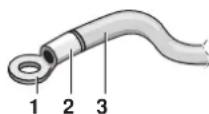
1 Kpyrtnb otOrhytb pa3bem
2 YcTaHOBnTe N3OJIaUNOHHyBOTyNkY
3 PpOboKa
He npncoeinHnTe K OndHn Toi Je KneMm NcToHHa nTahnnpoBoda, pa3nnuauuuece no copTaMeHTy. (Ppocna6nHn CoeHNHeHn MoKet npOn30Tu nepepeB.)
- Ppi noKluOeHn npoBOOB OINaKOBOrO ceHnnpicoeHNrTe nx cornaCHO pcyHky.



Icnonb3yte yka3aHnbl 3neKtpueckn npoBO. IpOuyho nOdoeHNHTe npoBO K KJEMME. 3aФNKcpyte npoBO, He npunara qpe3mepHo cnbl K KJEMME. MoMeHTbl 3aTAAKKyka3aHb B cIeDyIOuSe T6nue.
EcnKoHnIeHep He npekpaaaet pa6Oy, HnHOMep BTOPOKoJa He paBEN "02", NOBtOpNTe DeNCTBne 4.
EcHn HApxHbI arperaT He BkIOueH,Ha DnCnIeepyNtTa
DnCTaHnOHHoro ynpabEnHn OTo6paKaaetc KaD"UH"nn "UH"
cm. pa3dEe "PpO6HbI 3anyck" Ha cTp.12).OHaKo MoXHo
npoOnJHTb HAcTpoKy 3ToI FyHKuIN, NocKoNkY 3TN
coo6uHHe nPpmeHmbl ToBko dner HApxHbIX arperatOB.
Iocne HAcTpoKn 3ToN cyHKuIN BkHIOHTe HApYKbH arpera Tpeep np6bHm 3aNyckOM daHHoro arperata.
Ecni Ha dncnnee nybta nctaHcHNOHHoro ynpabneHna oTo6paKaetca npraa Oun6ka, cm. pa3den "PpObHbI 3anyck" Ha cTp.12 i pyKoBOcTBo no 3KcNlyatauHn HApXHoro arperata.YcTpaHnte HeNCnpaBHOCTb.

EcnBHeHHe cTaNueckoe DaBnHeNe npeBbIaet 100 Pa, He nCIOB3yIte FyHKUIO ABOtOMaTnecko peYINPOBKN BO3DyUHORO NOTOKA.
Ecn nocne perynipOBKn BO3dyuHoro noTOKA OTCyTCTBYOT N3MeHeHn B BEHTNIAUHOHBIX KaHaIax, BbINOHNTE HAcTpOky ABOTMaTuYeCKoI peynipOBKn BO3dyuHoro NOToKa NOBtOpHo.
O6paTntecb K CBOeMy DnIepy, ecnn nocpepyInpOBKn BO3DyUHoro NOTOKa OTCYCTBYOTn3MeHeHn B BEHTnIaUIOHHbIX KaHaJnx nocneBblONHeHn npo6Horo 3anycka HapyXHoro arperata nnI nepeMeueHn KOHNIOHOhepa.
Ecn npmeHOTc BCNOMORAeBbHbe BHTnTOpbl, Hapyxhbl arperat nIg opa60Kn BO3yxa nn 6nK HRV, noCoeHNHeHHb ype3 BO3yXoBOd, He nCnoJb3yTe nyIbT Dy nn ynpaBneHna aBTOMATUeckO peYnIpOBKO B03dyuHoro nOToka.
Iocne n3MeHeHn BcHTnLzIOHHbIX KaHaIOB NOBTOPOB BbINONHITe HAcTPOy ABTOMaTHUeCKO perynipOBKn BO3DyUHoro NOTOKa, HauHna C DeiCTBn 3,Kak ONCaHO Bblie.
Icnonb3oBaHne npbTa dncTaHnOHHoro ynpaBneHna
Y6eINTeB TOM, YTO BO BHYTpEHem arperate DnB TOpORO KoJa pexkma 21 3aHaHO 3NaHeHne 01 (3aBOdCKa HacTPOka). N3MeHNTe BTOPO KOD B COOTBeCTBm C BHeUHM CTaTHueckm DaBNeHEm NOcEOHNHeHNOB3dyXoBOda, KaK Noka3aHO B Ta6nue 2.
PnncnoB3oBAHm2nybTOB DYcneyET nepeBeCTn OINH nHxB OCHOBHON peKIM, a pyroB peKIM CY6BJIOK.
NEPEKNIIOUeyHEOCHOBHO/CYEBJOK
Bctabte OTBepkcy C nIOCKMM WJINcEM B NOIOCTb MeKdy BepxHn HIXHHe Yy, Bo3eJeCTByc 2 CTopoOH, OCTOPOKHO CHIMITE BepXHIOU Yactb. (CM. pucyHok 18) (NeuTHa nnata NybTa DY npCoeDHHReTc K BepHe qactn nyIbTa Dv.)
IpepeBeHnTe nepeKIOuHaTeNb CMeHbI peKIMa OCHOBHO/ CY55JOK Ha oHOB n3 nIaT PC nyIbTa Iy B noOnKeHne S. (CM.pncyHok 19)
(ПepeknoyateNBpyrOTo nIbTa DnCTaHOnHO rypabHeNn octabTe B noJoxeHm M.)
1 NeuHnna nynbTa D
2 3aOdkaHaCTpoKa
3 Heo6xOIMO n3MeHnB HAcTPOkY ToIbKO dIa OJHO rNJIbTa D
KOMnbIbTepeHoe ynpaBHeHne (npuHynteHbHoe BbIKIOueHne H Oepaunn BKIOUeyHra/BbIKIOUeyHna)
1 CneuPnkaun npoBOOB u kaaHn no 3eKtpueckomy MoTAty
IIOKIOUHTeBXOcHApyKHOCTOPOHKKNMeMMAMT1NT2 KEMMHOKOJOKn(npoBOKapeepaDAnHHbxCnybTaDY)
UHCTKa BO3dUwHbIXΦHbTpOB
OuHuaTb BO3DyHbIe FnIbTpbl Heo6xOIMo TOrda, KOrda Ha dncnnee NOBUTc CmBOBn" (NOPA YNCTNTb FInlbpT).
Ecnn KOHdNIOHeP 3KcNpyATnpyETcB MecTax, rIe BO3dyxCnIbHO 3aqrpa3HeH, YnCTky FmNbTPOB Heo6xOJIMO npOn3BOJtB Haue.
EcnnnHbTp HeBO3MOxHO OCHNTb OT rpa3n, 3aMeHHTe ero. (Cmehhbln HbTp nocTaNrEcTn oTdEnbHomy 3aka3y.)
1 OtkpoTe Bo3dyxo3a6opHyo peWetky (TOnbKO dNra Bo3dyxo3a6opa C HnKHe CTopoHbI).
OndOBpeMeHHo CdbHbTe o6e pyK, KaK Noka3aHo, IN NOTAHNTe INX BHN3.
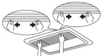
Ecn npedycmToHbI cHmnte nx C KpkoOB.

2 CHMMTe BO3DyUHbIe fNJIbTpbl.
CHIMITE BO3DyUHbIe CnBtpbl,NOTAHy IN XTKaHB BBepx (BO3DyXo3a6Op c 3aHHei CTopoHbI) HIN BHIN3 (BO3DyXo3a6Op c HIXKHei CTopoHbI).
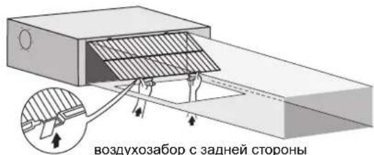
B03dyx03a6op c HIXKHei CTOPHOI

3 OuHCTHTE BO3dyHbI htp.
BocnoIb3yIteCb nbIeCOCOM (A) nIN npoMoTe BO3dyHbI ΦnIbTp BDOI (B).
YnCTka HapyKhbix nHaHei
HcTky cIeDyET npOn3BOuNTb C nOMOuM MAnKoTKaHn.
IyraJeHn TpyHOBBIOBIMBX NATEH HcNoJIb3yTe BOy IIN HeITpaJIbHOe MOIOue CpeCTBO.
OuHCTnTe 3aKpblTyU peWlEly Ko3dyXo3a6OpHNka.
TIPIMMEYAHNE

He npimHeHnTe nIy NCTKn 6eH3nH, KePOcIH, pactBOpHTeIN, abpa3nHBhle MaTePmaJIb IN HNCEKTHUINDbI. 3To MoKet Bb3BaTb ObecuBeHNBaHne INI DeΦopMaHIO KOpTyCa KOHNHOHaepa.
He donyckaIte nonadaHna Bnarn Ha Koprnyc BHyTpeHHero 6noka.3To MoKet npBecTu KnopajehnIO 3JKeTPOTOKOM Nn BO3ropaHNO.
BkHoueHne nocJe dntTeNbHoro npocToA
Ponu3BeDnTe CneDuOuHne Oeepaunm:
PpOBepbTe, HETIINIOCTOPOHHHN PpeMToB, ppenTCTByIOxN BxOdy N BbIXOy BO3Dyxa. Ecnn ectb, y6epnte ux.
PpoBepbTe HaedKHOCTb 3a3eMJIeHnI.
OuCTTE BO3dyHbI ΦnIbTp n HapyKhIe NaHeI N KOHNIOHOpe.
No 3aBepeHnOChcKHe 3a6yDbTe NoCTaBnTp HmecTo.
BknHouHTe pa3MbkaTeN bEN NITaHn.
Pn noahe nTaHna 3arOpntc DaCnneynyBta ynpabHeHna.
Дя 3auntb6noka yctahabnBaTe OCHOBH BbIKHOATEJIb nHTAHIBpa6oyee noJoxKeHHe XOTb3a6YacOBdoHaayana pa60tbl.
Peped BbIKIOeHHeM KOHNIOHepa Ha dNITeIbHbI cpoK
IpepeBeDte KOHNIOHOEP B pexm TOJbKO BEHTNJLIAHn DaTe emy nondno npabOToB b 3TOM pexmme, yTO6bl npocuHTb 6nok.
CMOTPNTe HNCTpyKUHNO no 3KcnnyatauHn HApyXHoro arperata.
OTKIOHHTe NITAHNE.
Ecn nntaHHe OTKNoeHo, HekotopbIe cenn CnCTembl HaxoJrTcNd HapnKHeM, daKe ecn OHa He pa60Taet.
Iucnne nynbta nctaHcnoHHoro ynpabNeHna BbIKIOaetc npn nepemuehen rnaBHORO BbIKIOaTeB BBIKIOeHHoe nonoxKeHne.
yTnna
EmoHTax arperata, ydaIeHne XOJOnbHoro areHTa, Macna n dpyrnx Yactei DoJXHb IPOBOINTBcB B COOTBeCTBm C MeCTHbIM n 6ozerocdyapctBeHHbIM 3aKHOJaTeJIbCTBOM.
3JIeKTpUeCKa cxema
MECTHARIPOBOKAKAPA3bEMKINEMMA C BINTOBbIM KPEJIENHEM
BLK : YEPHbI PNK : PO3OBbl BLU : CINHn RED : KPACHbl BRN : KOPNUHEBbl WHT : BELbl GRN : 3EJIeHbI YLW : XENTbl ORG : OPAHKeBBbl
A1P. .NEUATHAJIATA
A2P. .NEUATHAJIATA (BEHTNIJTOP)
C1. KOHDEHCATOP
C105. KOHDEHCATOP
DS1. CEJIKTOPHBI IPEEKLIQUATEJB
F1U. .IPEOxPAHITIEL (T,3,15 A,250 B)
F2U. .IPEOxPAHITIEL (T,5 A,250 B)
F3U. .IPEOxPAHITIEL (T,6,3 A,250 B)
HAP. JAMbl INDINKAUM
K1R. .MAGHTHOE PEIE
L1R. .PEAKTOP
M1F. .IBNATIEL (BHTPEHHN BEHTNIJTOP)
M1P. .IBNATIEL (IPEHAXHBI HACOC)
PS. .IMNUbCHbI NCTOCHNK NTATAHIA
Q1DI. .YCTPOICTBO 3AUITHORO OTKIOUCHENRA
R1. .PE3NCTOP (DATUK TOKA)
R2. .PE3NCTOP (DATUK TOKA)
R1T. .TEPMNCTOP (BCACsIBAHNE)
R2T. .TEPMNCTOP (KNDKOCTb)
R3T. TEPMICTOP (3MEEBNK)
S1L. .IIOJIABKOBOE PEIE YPOBHA
V1R. .IIOJHbIMOCT
V2R. .BLOK NITAHNIA
X1M. .KIEMMHAR KOJODKA (3JEKTPONHTAHNE)
X2M. .KIEMMHAR KOJODKA (YIPABJIENHE)
Y1E. .OBMOTKA 3JEKTPOHHO
TEPMOPEYINPYUQERO BEHTINRA
Z1C. .ΦEPPITOBBI CEPDEHNIK
Z2C. .ΦEPPITOBBI CEPDEHNIK
Z1F. .ФИЛБТР ПОДАВLEHNI POMEX
PA3bEM(DONONHHTeJIbHbIe PnIHADJIeKHOCTN)
X28A...PA3bEM(ДЯ ПОВODКИ NCTOCHNKA
PITAHNY)
X33A...PA3bEM(ДЯ ПОВODKN)
X35A...PA3bEM(ДЯ ПОВODKN NCTOCHNKA
PITAHNY)
X38A...PA3bEM(ДЯ ПОВODKN)
WIEDR REMOTECONTROLLER IpoBDOHnIyIbI DnCTaHIOHOYnpabHeHHA (OPTIONAL ACCESSORY) (DOnoJIHITeHbHa npHaIaNEXHoCTb) SWITCH BOX (INDOOR) PaCppeJeHtEhBaKop06ka(BHyTpEHnRA TRANSMISSION WIRING IpoBOKa ceHnpeJaH CENTRAL REMOTE CONTROLLER LcHTpaHbHnIpyIbI dy INPUT FROM OUTSIDE Bxod chapyKn COMMON POWER SUPPLY O6uH NCTOHNIK PHTAHNA
ПИМЕЧАНО

- INTOINb3yIe TOJIbKO MEHbIE NPOBODA.
- ECINI NCIIOJIb3yETCRAIHTPAJIbHbI IYbLT Dc, CM.PYKOBODCTBO IIO NOIKIIQUEHIO K BLOKY.
- ECLI NOCDOENHEBBI BHEHNE IPOBODA, C NOMOUIIO NylbTA DMY MOXHO BBISPATPBATOBY PEXIME INPHYNTIELHO BbIKIOUeyHNAI ONEPAUHIO YNPABJEHNAI BKIOUeHEM/BbIKIOUeHEM. IONOHHTIELHBIE CBEDEHNA CM. B PYKOBODCTBE NOMOHTAXY.
- CM.PYKOBODCTBO NMOHTAXY.
Icindekiler Sayfa
Montaj oncesi. 1
Boruyalitimproseduru
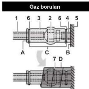
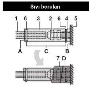
1 Boru yalitim malzemesi (sahada temin edilir)
2 Konik somun baglantisi
3 Baglanti yalitimi (uniteyle birlikte verllir)
4 Boru yalitim malzemesi (ana unite)
5 Ana unite
6 Kablo bagi (sahada ledarik edilir)
7 Gaz borulari icin ortam 1 szidirmazlik pedi (uniteyle birlakte verilir) Siv borulari icin ortam 2 szidirmazlik pedi (uniteyle birlakte verilir)
A Dikisler yukar gelir
B Tabana sabitleyin
C Boru yaltim malzemesi disindaki parcayi sikin.
D Üntenin tabanindan konik somun baglantisin nüerine kadar sarin.

MCA: Min. devre Amp (A)
MFA: Maks. Sigorta Amp (A)
NOT
Ayrintili bilgi icin, teknik veri kitabindaki "Elektrik

verileri'bolumenebakin.