
GDS3705 - Audio intercom GRANDSTREAM - Free user manual and instructions
Find the device manual for free GDS3705 GRANDSTREAM in PDF.
| Product Type | Audio intercom |
| Brand | Grandstream |
| Model | GDS3705 |
| Power Supply | PoE IEEE 802.3af (Class 3) or DC 12V, 1A |
| Connectivity | Ethernet RJ45 10/100 Mbps |
| Network Protocol | TCP/IP, UDP, HTTP, HTTPS, DHCP, etc. |
| Operating Temperature Range | -30 °C to 60 °C |
| Storage Temperature Range | -35 °C to 60 °C |
| Operating Humidity | 10% ~ 90% RH (non-condensing) |
| Installation | Surface mount or flush mount (flush mount kit sold separately) |
| Package Contents | 1x GDS3705, 1x mounting frame, 1x drilling template, 4x rubber gaskets, 6x screws |
| Configuration | Via HTTPS web interface (port 443), GS_Search tool to find IP address |
| Lock Relay | 3 terminals (NC, NO, COM) for electric lock (current or no current) |
| Care and Cleaning | Clean with a soft dry cloth. Do not use abrasive products or solvents. |
| Security | Anti-tamper screws, mandatory admin password change |
| Spare Parts and Repairability | Use only genuine Grandstream parts. Contact technical support. |
| General Information | IP audio intercom for access control, compatible with Grandstream access management systems. |
Frequently Asked Questions - GDS3705 GRANDSTREAM
User questions about GDS3705 GRANDSTREAM
0 question about this device. Answer the ones you know or ask your own.
Ask a new question about this device
Download the instructions for your Audio intercom in PDF format for free! Find your manual GDS3705 - GRANDSTREAM and take your electronic device back in hand. On this page are published all the documents necessary for the use of your device. GDS3705 by GRANDSTREAM.
USER MANUAL GDS3705 GRANDSTREAM
C O N N E C T I N G T H E W O R L D
Grandstream Networks, Inc.
126 Brookline Ave, 3rd Floor
Boston, MA 02215. USA
Tel: +1 (617) 566-9300
For Warranty and RMA information, please visit
www.grandsstream.com
EU Agent:
Picus Advisors Ltd
Taivalmaki 9F1-02200 Espoo, FINLAND
https://www.picus.fi
Note: For European Union only
GDS3705
Audio Door Access System
Quick Installation Guide
Content
English. 1
简体中文. 10
Espanol. 19
Francais. 28
Deutsch. 37
Italiano. 46
Pycckn. 55
Portugues 64
Polski. 73
PRECAUTIONS
- Do not attempt to disassemble or modify the device
- Strictly follow the requirement of power source
- Do not expose this device to temperatures out the range of -30^ to 60^ for operating and -35^ to 60^ for storage
- Do not expose this device to environments outside of the following humidity range: 10 - 90% RH (non-condensing)
- Please strictly follow the instruction to install or hire professionals to install properly
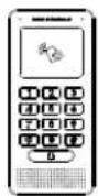
PACKAGE CONTENTS
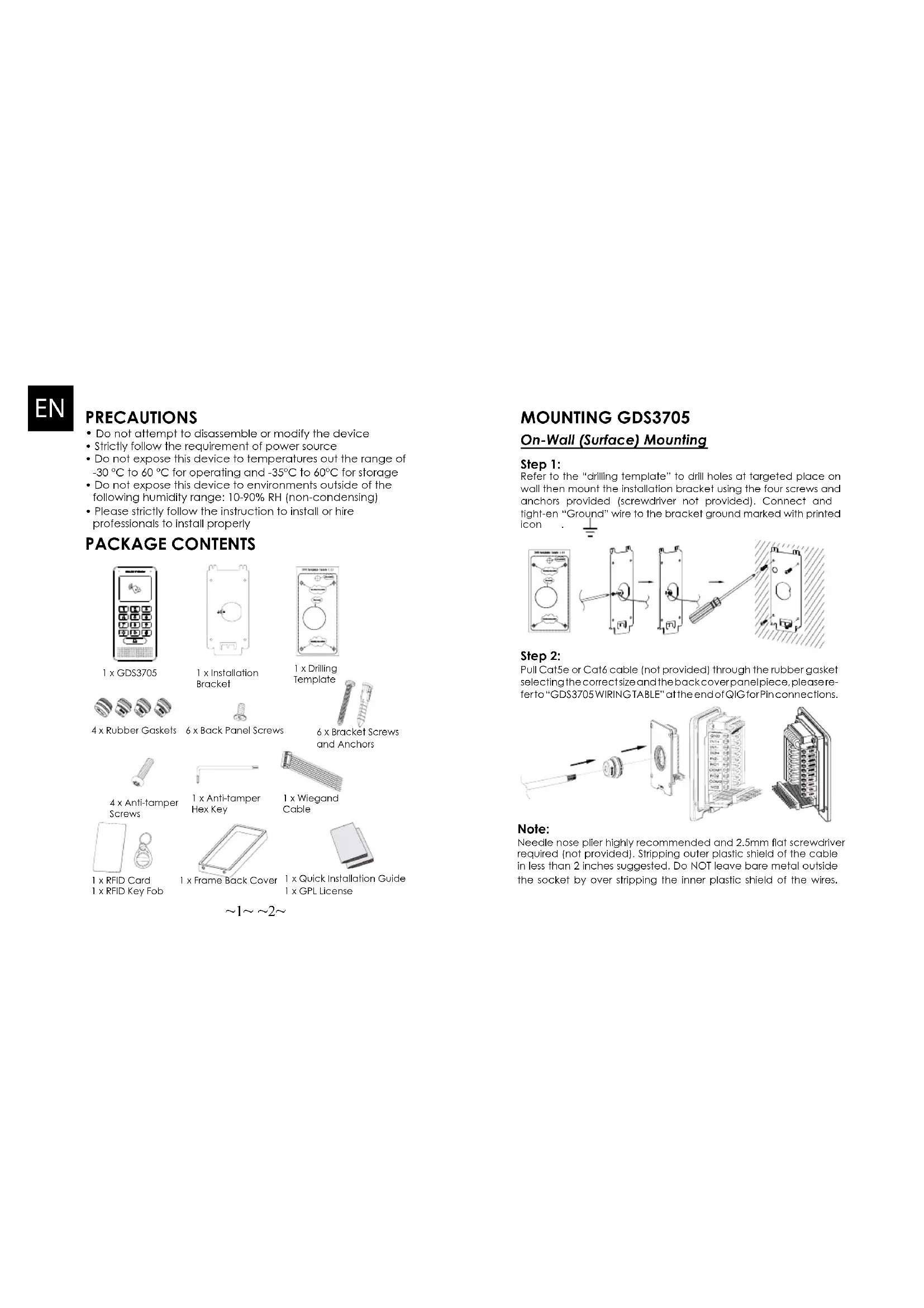
1xGDS3705
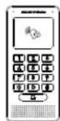
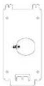
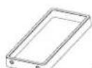
1 x Installation Bracket
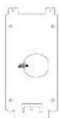
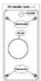
I x Drilling Template
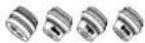
4x Rubber Gaskets

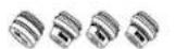
6 x Back Panel Screws

6 x Bracket Screws and Anchors

4 x Anti-tamper Screws
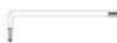
I x Anti-lampers Hex Key
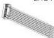
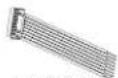
1 x Wiegand Cable
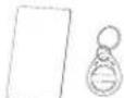
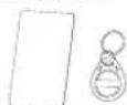
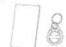
1 xRFID Card 1 xRFID Key Fob
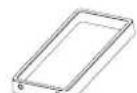
1 x Frame Back Cover

1 x Quick Installation Guide 1 x GPL License

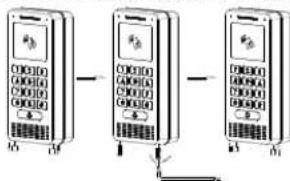
MOUNTING GDS3705
On-Wall (Surface) Mounting
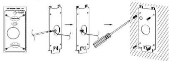
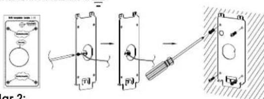
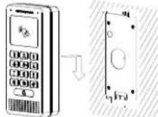
Step 1:
Refer to the "drilling template" to drill holes at targeted place on wall then mount the installation bracket using the four screws and anchors provided (screwdriver not provided). Connect and tight-en "Ground" wire to the bracket ground marked with printed icon
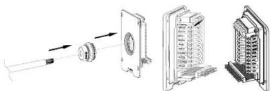
Step 2:
Pull Cat5e or Cat6 cable (not provided) through the rubber gasket selecting the correct size and the back cover panel piece, please refer to "GDS3705 WIRING TABLE" at the end of QIG for Pin connections.
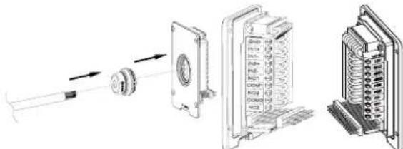
Note:
Needle nose plier highly recommended and 2.5mm flat screwdriver required (not provided). Stripping outer plastic shield of the cable in less than 2 inches suggested. Do NOT leave bare metal outside the socket by over stripping the inner plastic shield of the wires.
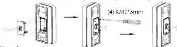
Step 3:
Make sure the "Back Cover Frame" is in place, the wired back cover panel is good. Flush the back cover panel piece with the whole back surface of device, tighten if using the screws provided.
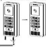
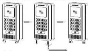
Step 4:
Take out the two preinstalled anti-tamper screws using the hex key provided. Carefully align the GDS3705 to the metal bracket on wall, press and pull the GDS3705 down to the right position.
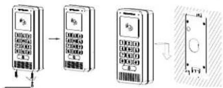
Step 5:
Install the two anti-tamper screws back using the hex key provided (do NOT over fighten the screws). Cover the two screw holes on the bottom of "Back Cover Frame" piece using the two silicon plugs provided. Final check and finish the installation.
In-Wall (Embedded) Mounting
Please refer to the "In-Wall (Embedded) Mouting Kit", which can be purchased separately from Grandstream.
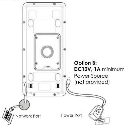
CONNECTING THE GDS3705
Refer to the illustration below and follow the instructions on the next page.
POWER OFF GDS3705 when connecting wires or inserting/removing the back cover panel piece!
Option A:
RJ45 Ethernet Cable to (Class 3) Power over Ethernet (PoE) Switch.
Note:
Choose Option A if using PoE switch (Class 3): OR: Option B if using 3rd party power source.
Option A
Plug an RJ45 Ethernet cable into the (Class 3) Power over Ethernet(PoE) switch.
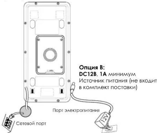
Option B
Step 1:
Select an external DC12V, minimum 1A power source (not provided). Wire correctly the "+" cable of the power into the "12V, GND" connector of the GDS3705 socket (refer to the previous mounting page for instruction). Connect the power source.
Step 2:
Plug an RJ45 Ethernet cable into a network switch/hub or router.
Note:
Please refer to "Step 2" of "MOUNTING GDS3705" and "GDS3705 WIRING TABLE" at the end of QIG for all the wiring and connection illustration and instructions.
GDS3705 CONFIGURATION
The GDS3705 is by default configured to obtain the IP address from DHCP server where the unit is located.
In order to know which IP address is assigned to your GDS3705, please use GS_Search tool as illustrated in following steps.
Note:
If no DHCP server is available, the GDS3705 default IP address (after 5 minutes DHCP timeout) is 192.168.1.168.
Step 1: Download and install GS_Search tool: http://www.grandsstream.com/support/tools
Step 2: Run the Grandstream GS_Search tool on a computer connected to same network/ DHCP server.
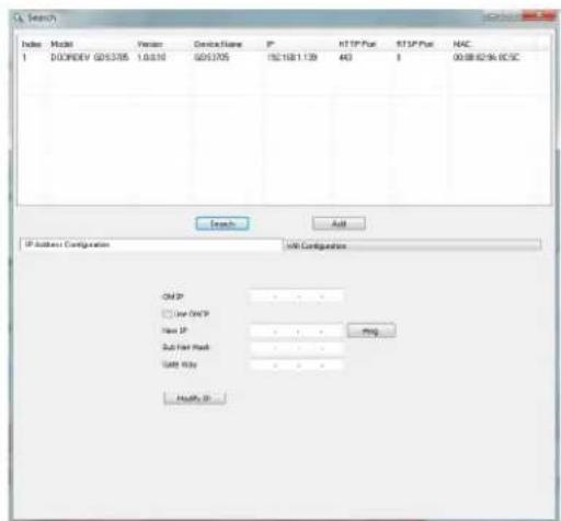
Step 3: Click on Search button to start device detection.
Step 4: The detected devices will appear in the output field as below.
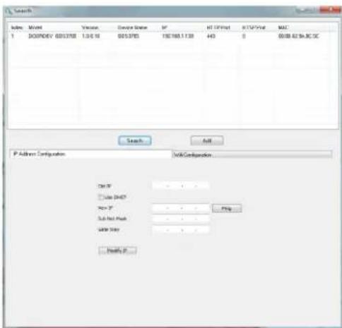
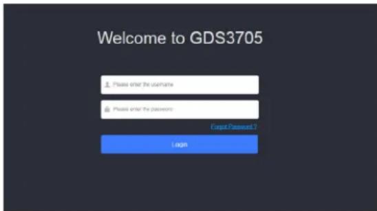
Step 5: Open the web browser and type the displayed IP address of GDS3705 with leading https:// to access the web GUI. (For security reasons, the default web access of GDS3705 is using HTTPS and port 443.)
Step 6: Enter username and password to login. (The default administrator username is "admin" and the default random password can be found at the sticker on the GDS3705).
Note: For security reasons, make sure to change the default admin password from System Settings > User Management.

Step 7: After login into the webGUI, click the left side menu in the web interface for more detailed and advanced configuration.
Refer to online documents and FAQ for more detailed information:
http://www.grandstream.com/our-products
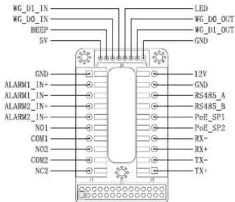
GDS3705 WIRING TABLE
| Jack Pin Signal Function | ||
| J2(Basic)3.81mm | 1 TX+(Orange/White) | Ethernet, PoE 802.3af Class3.12.95W |
| 2 TX-(Orange) | ||
| 3 RX+(Green/White) | ||
| 4 RX-(Green) | ||
| 5 POE_SP2 (Blue + Blue/White) | ||
| 6 POE_SP1 (Brown + Brown/White) | ||
| 7 RS485_B | RS485 | |
| 8 RS485_A | ||
| 9 GND | Power Supply | |
| 10 I2V | ||
| J3(Avanced)3.81mm | 1 GND Alarm GND | |
| 2 ALARM1 IN+ | Alarm IN | |
| 3 ALARM1_IN- | ||
| 4 ALARM2 IN+ | ||
| 5 ALARM2_IN- | ||
| 6 NO1 | Alarm Out | |
| 7 COM1 | ||
| 8 NO2 | Electric Lock9 COM2 | |
| 10 NC2 | ||
| J4(Special)2.0mm | 1 GND (Back) Wiegand Power | GND |
| 2 WG_D1_OUT (Orange) | Wiegand Output Signal | |
| 3 WG_D0_OUT (Brown) | ||
| 4 LED (Blue) | Wiegand Output LED Signal | |
| 5 WG_D1_IN (White) | Wiegand Input Signal | |
| 6 WG_D0_IN (Green) | ||
| 7 BEEP (Yellow) | Wiegand Output BEEP Signal | |
| 8 5V (Red) Wiegand Power Out | put | |
For more details regarding GDS3705 wiring, please refer to User Manual.
| Electric Lock GDS3705 Connection | Door | |||||
| Type Power On Power Off NC2 | NO2 COM2 | Normal Status | ||||
| Fail Safe Lock Open | ■ ▪ | Lock | ||||
| ■ ▪ | Open | |||||
| Fail Secure | Open Lock | ■ ▪ | Lock | |||
| ■ ▪ | Open | |||||
| NOTE: * Please select the correct wiring based on different electric strikebacklock and the normal status of door. * Electric Magnetic Lock will work at Fail Safe mode ONLY. | ||||||
Note:
1) Power PoE_SP1, PoE_SP2 with DC, the voltage range is 48V~57V, no polarity.
2) Power with PoE the cable wiring:
- PoE_SP1, brown and brown/white binding
- PoE_SP2, blue and blue/white binding
3) DC Power could be correctly sourced from qualified PoE Injector.
This product is covered by one or more of the U.S. patent (and any foreign patent counterploths thereof) identified at www.cmpdents.com.
ZH
注意事项
http://www.grandstream.com/our-products

4 x Vis anti-effraction
1 x Clé hexagonale anti-effraction
1x Cable Wiegand
1 x Cartes RFID 1 x Porte-clles RFID

1 x Couvercle aniere

1 x Guide d'installation rapide 1 x Licence GPL
MONTAGE DU GDS3705
Montage mural (en surface)
Etape 1:
http://www.grandsstream.com/our-products
TABLE DE CONNEXION DU GDS3705
| ConnecteurPI | NSignaFlonction | |
| J2(Basique)3.81mm | 1 TX+ (Orange/Blanc) | Ethemet, PoE 802.3af Class3, 12.95W |
| 2 TX- (Orange) | ||
| 3 RX+ (Veri/Blanc) | ||
| 4 RX- (Veri) | ||
| 5 PoE_5P2 (Bluc + Bluc/Blanc) | ||
| 6 PoE SP1 (Marron + Mar-ron/Blanc) | ||
| 7 RS485 B | RS485 | |
| 8 RS485_A | ||
| 9 CND | Source d'alimentation | |
| 10 L2V | ||
| J3(Avantée)3.81mm | 1 CND Masse Alarme | |
| 2 ALARM1_IN+ | Entrée Alarme | |
| 3 ALARM1_IN- | ||
| 4 ALARM2_IN+ | ||
| 5 ALARM2_IN- | ||
| 6 NO1 | Sortie Alarme | |
| 7 COM1 | ||
| 8 NO2 | Verrouillage Electrique9 Co | |
| 10 NC2 | ||
| J4(Speciale)2.0mm | 1 CND (Noir) Masse Wiegand | |
| 2 WG_D1_OUT (Orange) | Signal de sortie Wiegand | |
| 3 WG_D0_OUT (Marron) | ||
| 4 LED (Blou) | Signal de sortie LED Wie-gand | |
| 5 WG_D1_IN (Blanc) | Signal d'entree Wiegand | |
| 6 WG_D0_IN (Veri) | ||
| 7 BEEP (Jaune) | Signal de sortie Beep Wiegand | |
| 8 SV (Rouge) Alimentation Wie-gand |
MEPbI IPEAOCTOPOXHOCTN
He nItaIteb otKpbibatb, pa36npaTb Hn H3MeHrtb yctpOCTBO
Ctporo co6aOdaaTe Tpe6oBaHnI nCTouHHKa nHTAHN
-He noaBepraTe BO3AeCTBnHO TEMnepatypbI BHE dHana30Ha ot-30°C 60°C npn 3Knayataun n oT -35°C 60°C npn xpaehHH
HeOnyckaeTcHCCNoA30BAtyCTPOIcTBnPnTHOCHTeALHO BAOXHOCTN BHE ANa3OHa 10-90 (6e3 KOHAcHcTa)
- PnKAsyIcTa, cTporo CaeayIe NHeCTpykUINM NO yCTAHOBKe HAIIMNTpePocceCNOHAAAD AII PPABNAHOU YCTAHOBKN
KOMIIAEKTIOCTABKN
1×GDS3705
1XKpoHILITEHHAAYCTAHOBKN
1x山a6aoh 0BepCTH
4XPe3nHOBbIe POKAaKIN

6X BNTBt 3QHeH PAnHEA

6X BInThbN AHKBeBp KPOHUTeHa
1xIeCTnHpaHHKAKOHPOINHOB3AOMHOTCYpOCTb
I x KabeAb Wiegand

4XBHHTbNPOTIOBBOAOMHOTOCYPTOINCTBA
1xKapTa paAnohactoTHO HnEHTnPAKauu 1 xRFID KAPU

X1KpTKepyKOBCTBO NOA308AEL 1XAMHeHnGPL
55 56
MOHTAX GDS3705
HacteHHbI (noBepxHocTHbI) MOHTAX
War 1:
Ncnoa3yra "W6oohAAR CBepeHn" npocBepante OTBepCTNA Ha BbpaHOM MeCTe HA CTHe, 3ATEM CMOHNTpyTe YCTAHOBHOHBKPOHHTEIN,NCNOAB3y4 BHTA N OHKEpA, BXOARNE B KOMTAERT NOCTABKN (OTBepTKB KOMPAKT He BXOANT).IOAKAOHTNE IN 3AKPENTE PPOBOAD 3a3eMaEHn K 3eMa KPOHHTeHa, NOMeeyHHOHKOH.
War 2:
PpOHTHHe Ka6eAb Cal5e HAn Cal6 (He BxOaRt B KOMTAEK) NoCTABKN)peep3pe3nHOyIO npKaIAkky, BbIbpaB HYKbIy PA3MeP. H3AHIIO NaHEa, NOXAAUYCTA, CMOTPe 1871002410000000000000000000000000000000000000000000000000000000000000000000000000000000000000000000
PnmeaHne:
PekomeHcyTc Hcnoabobt octpoy6bI n Nocckyo OTBepTK 2.5 MM (HE BxOaRT B KOMPAeK T NOCTABK).PEKOMEHOBAHO 3CHLIATb npoBOa Ha MeHee Yem 2 AIOMa. HE OAnyCKaTe HAAMe OraEHHORo METAA BHE PO3eTK, B CaeCTBne H3bIOTOHOrO CHTIN NACTIKOBn H3OALIN NPOBOA.
Uar 3: Y6eAHTeB, HTo "3aHnKpbIka" Ha MeCTe, 3aHnKpbIkaA
npoBOOB B NOPAAke. YcTaHOBnTE 3aOAnluo pAMky n 3aHIO
NAHEoY cTPOCTB0, 3aTHnue C NOMOULBO BHNTO, NOCTABAREMIX

War 4: Bbkyntte ABA BnHTa 3aunTb OT BCKpbITN C nmoouBIO UeCTHPTPAHHOT KAOHa. TTOATEABHO npHKMITE GDS3705 K MetaAneckOn CKo6e Ha CTHe, HAKMITE NOTAHTE GDS3705 BH13 B HNYKHe NOAOXEHNE.
War5: BkyTInTe ABA BNHTA 3aunHbI O BCKpbHnBnHTbO6pHtC nmoLIOu LIECTHPaHHORKAIOH (He nepetraNBAte BNHTb). 3aKpoNTe ABA OTBepCTNAR BA HINHOH qACTN "3aHEK KpbUHK"HCNOAB3yABE pe3HOBbIX 3aayUKN.CaeAOnTe cHNAHHy npOBEPKHY 3aBepUHTE yCTAOHBKY.
HacteHHbB (BCTPOeHHb) MOHTAX
TOKaAYcTA, HNOAByTE "KOMNAERT AAR HACTeHHoro
(BCTPOeHHOrO) MOHTAKa", KOTOpB MoXHO OTeAebHO 3Ka3aTb B
KOMnAHn Grandstream.
57 58
IOAKAIOUOHENE GDS3705
CMOTPITE N36paxeHNE HNHE N CEAUYTE INCHCTpyKUNAM HA CEAUYUEN CTPAHNIUE.
OTKIOHTNEIITAHHE GDS3705 npn NOAOKIOHcHIN PPOBOAOB NNN NOACOEANHEHN/OTCOEANHEHN 3aAHeN pOHEH
OnuaA:
RJ45 Ethernet Ka6eAb B (KAcc 3) Power over Ethernet (PoE) kommtyarop.
PnmeaHne:
Bb6epnteOnuA, npn HcnoAo3oBAHn PoE KOMMyTaTopa (Kaacc 3);
NtAH:OnuB, npn HcnoAo3oBAHn CTOpOHHe NCTOyHnKa nITAHN.
OnuA
Bcabe RJ45 Ethernet ka6eab B (Kaacc 3) Power over Ethernet(PoE) kommMyTatop.
Onua B
War 1:
BbIepeHTe BHEUHHN HCTOHNK NITAHNDC12B, MHNMYM 1A (He BXOANTB KOMPTAEK NOCABH).PABNAHBO NOAKAOHYTE,COBAOAR NOAOCOBKY"CHAOBOH Kabeab K pa3bemy "12V.GND"TH3a GDS3705 (NHCTpyKUN CMOTpHe Ha ppeBIAUYuec cTpaHnue). PNOAOKHYTE HCTOHNK NITAHN.
War 2:
PioknHtE hEmet KabeK cTeN, KomMyTatopy/ KOHeHTpatopy HAn Mapwpytnatopy
PnmueyaHne:
PAnayncta.Cmptne"War2Bpa3ae"MOHTAXGDS3705" n"TABANLYKABEbHOINPA3BOADKNGDS3705" B KOHcKe KpAeKoH INCTpyKUNNoYCTAHOBKEA HIO6paKeHNuHCTpyKUNPO PA3BOAENCOAENHEHNA.
KOHΦινγραύη GDS3705
No ymouhan GDS3705 Hactpoen Ha noanyehne IP-apeca ot DHCP-cebpepa,Ha KOTOPOM paonaooxeHO yctpoictBO.
Ara toro yto bby hatab kakoi IP-aapdec nphcBOeB Balaemy GDS3705, NOAAYaCTa HNCaAByTe CpeACTBO GS_Search. KAK NOKACAHO B HIXKCAEAUYOINXUARAX.
PpMueHHe:
Ecam DHCP HeocTyneH, IP-aapeGDS3705 no ymoaHnIO (hepe3 5 MmHT c TaMayTa DHCP) 6yTe1 192.168.1.168.
War 1: 3a rpya nte u yctanobite GS_Search tool: http://www.grandstream.com/support/foals
War 2:3anyctte GS_Search kOMnAHH Grandstream Ha KOMIbIopepe, noKMOHcHHom K ToJ Xe ceiN/DHCP-cebpEy.
War3: LLEKHTe Ha KHONky AARcYCKa 6HApXKeHNyCTpoCTB.
War4:O6hApxyKeHHoeYCTpOInCTBOOTOpa3ITcBNOAE BbIOaKaKAKoKa3aHO Hnke.
War 5: OTKpoIte Be6-6pay3ep N BBeIte OTo6paXeHHbI IP-aDpe GDS3705 HauHnA C https:// AaB XoDa B Be6 TIN. (No coo6paXeHennm 6e3oNACHOCTn, Aa Be6 aocTyna GDS3705 nCnoA3yET HTPS nOpt 443).
War 6: AAR BXOAG BBEANTE HMM NOAB3OBATEA IN NAPoA. (NMA NOAB3OBATEA DAMNHCTPATOPA NO yMOAHHIO - "admin", CAUYHbI NAPoA I NO yMOAHHIO MOXHO HAHTH Ha HAKAEKe HA GDS3705).
IpMmeHHe:No coo6pOKeHHaM 6eOnaCHOCTn, O83aTeAboHO hMeHInTe npAOB aAMNHcTpaTOpa NO yMOAnAHIO,pepeBa B CnCTeMHbIe HAcTpoKn > YnpabAAHHe NOAB3OBQTeAAM.
War7:IOCAAE BXOAA B Be6 TIN,LIEAKHHTe NO MEHNO CAEBB INTEPpeHcaAAR 60Aee AetaaBbIx H paCunpeHHbIX HACtpoek.
CMOTPTE 3AektpoHHbIe AOKyMeHTbI n pa3deEA FAQ dA8 60aee noapobHoi Hcnpmaun:
http://www.grandstream.com/our-products
TABELA DE Cabeamento DO GDS3705
| Jack-paizbem | Ums | Cinnafl Φунцья |
| J2 (Балары) 3.81mm | 1 TX+ (Оранхебу/Балы) | Poe 802.3af Klassc3.12.95W |
| 2 TX- (Оранхебу) | ||
| 3 RX+ (Зеленny/Балы) | ||
| 4 RX- (Зеленny) | ||
| 5 PoE_SP2 (Сини+Сини/Балы) | ||
| 6 PoE_SP1 (Корунов+Корунов/Балы) | ||
| 7 RS485_B | RS485 | |
| 8 RS485_A | ||
| 9 GND | БАСК ПИТСИЗ | |
| 10 T2V | ||
| J3 (Рослары) 3.81mm | 1 GND | Синоградотор Задмагн� |
| 2 ALARM1_IN+ | Alarm BxOД | |
| 3 ALARM1_IN- | ||
| 4 ALARM2_IN+ | ||
| 5 ALARM2_IN- | ||
| 6 NO1 | Alarm BxOД | |
| 7 COM1 | ||
| 8 NO2 | Зnevатрически замок | |
| 9 COM2 | ||
| 10 NC2 | ||
| J4 (Салары) 2.0mm | 1 GND (Черный) Wiegand GND | Wiegand bbyxoDAHоN CINHДA |
| 2 WG_D1_OUT (Оранхебу) | ||
| 3 WG_D0_OUT (Корунов) | ||
| 4 LED (Сини) | Wiegand bbyxoDAHоN CINHДA CIND | |
| 5 WG_D1_IN (Балы) | Wiegand bbyxoDAHоN CINHДA | |
| 6 WG_D0_IN (Зеленny) | ||
| 7 BEP (ЖБаты) | Wiegand bbyxoDAHоN 3BvKOВо NCHДA | |
| 8 S' (Красьы) | Wiegand bbyxoDAHоN MOLUHOCtB |
Aa 60ae noapobno Hncpopmaun O kaebbho np3BOaKe GDS3705, NOKAAYIcTc, CMOTPnTE PyKOBOCTBO NAOsbOCTAE.
http://www.grandsstream.com/our-products
TABLEA DE Cabeamento DO GDS3705
| TomadaPIN Sinali:função | ||
| J2(Básico)3.81mm | 1 TX+ (Laranja/ Branco) | Ethemet, PoE 802.3af Class3, 12.95W |
| 2 TX- (Laranja) | ||
| 3 RX+ (Verde/ Branco) | ||
| 4 RX- (Verde) | ||
| 5 PoE_5P2 (Azul + Azul/ Branco) | ||
| 6 PoE SP1 (Castanho + Castanho/ Branco) | ||
| 7 RS485 B | RS485 | |
| 8 RS485_A | ||
| 9 CND | Fonde de alimentação | |
| 10 V2V | ||
| J3(Avantagem)3.81mm | 1 CND Alteramento do Alarme | |
| 2 ALARM1_IN+ | ALARM IN | |
| 3 ALARM1_IN- | ||
| 4 ALARM2_IN+ | ||
| 5 ALARM2_IN- | ||
| 6 NO1 | Alarm Out | |
| 7 COM1 | ||
| 8 NO2 | Fechadura Elétrica9 COM | |
| 10 NIC2 | ||
| J4(Espezial)2.0mm | 1 CND (Negro) Wiegand Power GND | |
| 2 WG_D1_OUT (Laranja) | Sinal de saía Wiegand | |
| 3 WG_D0_OUT (Castanho) | ||
| 4 LED (Azul) | Sinal de saía Wiegand LED | |
| 5 WG_D1_IN (Branco) | Sinal de entrada Wie-gand | |
| 6 WG_D0_IN (Verde) | ||
| 7 BEEP (Amarelo) | Beep do sinal de saía Wiegand | |
| 8 SV (Vermelho) | Saida de energia Wie-gand | |