HDC Classic - Pressure washer Kärcher - Free user manual and instructions
Find the device manual for free HDC Classic Kärcher in PDF.
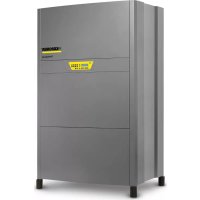
Download the instructions for your Pressure washer in PDF format for free! Find your manual HDC Classic - Kärcher and take your electronic device back in hand. On this page are published all the documents necessary for the use of your device. HDC Classic by Kärcher.
USER MANUAL HDC Classic Kärcher
Elektrischer Anschluss Maximalen Arbeitsdruck am Überströmventil einstellen Überströmventil einstellen EU-Konformitätserklärung Produkt: HochdruckreinigerTyp: 1.509-xxxTyp: 2.509-xxxEinschlägige EU-Richtlinien2006/42/EG (+2009/127/EG)2009/125/EG2011/65/EU2014/30/EUAngewandte harmonisierte NormenEN IEC 63000: 2018EN 55014–1: 2017 + A11: 2020EN 55014–2: 2015EN 60335–1EN 60335–2–79EN 61000–3–2: 2014EN 61000–3–12: 2011EN 61000–6–2: 2005EN 61000–6–4: 2007EN 62233: 2008HDC 20/8, HDC 20/8 H:EN 61000–3–3: 2013HDC 20/16, HDC 20/16 H:EN 61000–3–11: 2000Angewandte Verordnung(en)(EU) 2019/1781 Garantie Chairman of the Board of ManagementDirector Regulatory Affairs & Certification 10 DE- 9 Kundendienst Anlagentyp: Herstell-Nr.: Inbetriebnahme am: Prüfung durchgeführt am: Befund: Unterschrift Prüfung durchgeführt am: Befund: Unterschrift Prüfung durchgeführt am: Befund: Unterschrift Prüfung durchgeführt am: Befund: Unterschrift 11DE- 1 Please read and comply with these origi- nal instructions prior to the initial opera- tion of your appliance and store them for later use or subsequent owners. – Before first start-up it is definitely necessary to read the safety indications Nr. 5.956-309.0! – In case of transport damage inform vendor imme- diately. Notes about the ingredients (REACH) You will find current information about the ingredients at: www.kaercher.com/REACH DANGER Pointer to immediate danger, which leads to severe in- juries or death. 몇 WARNING Pointer to a possibly dangerous situation, which can lead to severe injuries or death. 몇 CAUTION Pointer to a possibly dangerous situation, which can lead to minor injuries. ATTENTION Pointer to a possibly dangerous situation, which can lead to property damage. – Please follow the national rules and regulations for fluid spray jets of the respective country. – Please follow the national rules and regulations for accident prevention of the respective country. Fluid spray jets must be tested regularly and the results of these tests must be documented in writing. – Please follow the safety instructions which are at- tached to the used detergents (normally on the packing label). The work station is located at the operating field. De- pending on the plant installation, other work-stations are located at the accessories (spraying units) that are con- nected to the feeder points. – Wear protective clothing and safety goggles to pro- tect against splash back containing water or dirt. – This system transports water to the down-the-line high pressure units with high pressure. This unit is permanently installed in a dry room. There must be a water and a power connection present according to the details provided in the technical specifica- tions. The temperature at the installation site should not exceed 40 °C. The high pressure water is distributed through a fixed network of pipes. – Only clean water may be used as high pressure medium. Impurities will lead to increased wear and tear or formation of deposits in the appliance. – Above 9 °dH, measures for hardness reduction may become necessary. – The use of recycled water must be prearranged with Kärcher in advance. DANGER Risk of injury! Follow the respective safety regulations when operating at gas stations or other dangerous areas. Contents Environmental protection EN 1 Danger or hazard levels EN 1 Symbols on the machine EN 1 Safety instructions EN 1 Proper use EN 1 Function EN 2 Safety Devices EN 2 Device elements EN 3 Start up EN 3 Operation EN 3 Shutdown EN 4 Technical specifications EN 4 Transport EN 5 Storage EN 5 Care and maintenance EN 6 Troubleshooting EN 6 Accessories EN 7 Installing the plant EN 8 EU Declaration of Conformity EN 8 Warranty EN 8 Customer Service EN 9 Environmental protection The packaging material can be recycled. Please do not throw the packaging mate- rial into household waste; please send it for recycling. Old appliances contain valuable materials that can be recycled; these should be sent for recycling. Batteries, oil, and similar substances must not enter the environ- ment. Please dispose of your old appli- ances using appropriate collection sys- tems. Please do not release engine oil, fuel oil, diesel and petrol into the environment Protect the ground and dis- pose of used oil in an environmentally-clean manner. Kärcher detergents are easy-to-dispose. This means that the functioning of an oil separator is not hampered. Please find a list of recommended detergents in the chapter "Accessories". Danger or hazard levels Symbols on the machine Risk of burns! Beware of hot com- ponents. Safety instructions Work-stations Personal safety gear Wear ear plugs to protect your ears against hearing loss while cleaning parts that produce high sound levels. Proper use Please do not let mineral oil contaminated waste water reach soil, water or the sewage system. Perform en- gine cleaning and bottom cleaning therefore only on specified places with an oil trap. 12 EN- 2 1 Locking tap (onsite)2 Temperature sensor3 Water shortage safeguard4 Float tank5 Advance pressure pump(HDC 20/8 H, HDC 20/16 H only)6 Crankshaft pump7 Safety valve8 Electro motor9 Manometer10 Pressure sensor11 Flow switch12 Overflow valve13 Swimmer valve14 Locking tap (onsite)A Pipeline/high-pressure output DN 15B Water supply, DN 20C Water overflow, DN 20The water flows back from the swimmer tank to the suc-tion side of the pump. The water level in the swimmer tank is kept constant by the swimmer valve. In case of failure of the swimmer valve, the water exits via the overflow. If the water supply is disturbed, the lack of wa-ter fuse will send an error message to the controls.The electric engine will drive the crankshaft pump. The pump transports the water under high pressure to the pressure side.The high-pressure water reaches the high-pressure output via the overflow valve and the pressure sensor. After that, there will be the high-pressure network of the operator.Remaining water will be routed back to the suction side of the pump by the overflow valve. If all consumer loads have been switched off, the overflow valve will switch to circulation. If the pressure at the output exceeds the maximum operating pressure at the output, the safety valve will open.– The appliance will be switched to READY mode by activating the release switch. The indicator lamp for operational readiness lights up. If the pressure in the systems sinks below the determined switch-on point due to the opening of a hand spray gun, the high-pressure pump will be switched on.– If the flow switch in the high-pressure line trips after closing all hand spray guns while the pump is run-ning, the pump is switched off again with a delay of 10 seconds (HDC 20/8) or 30 seconds (HDC 20/ 16). – If the system is ready and the high-pressure is not turned on, a timer is started, which will reset the readiness of the unit after 6 hours. The operation readiness indicator lamp goes off.Safety devices serve for the protection of the user and must not be put out of operation or bypassed with re-spect to their function.The safety mechanism against lack of water prevents the high pressure pump from being switched on when there is no water. The temperature sensor switches off the appliance as soon as the water temperature is too high.The winding protection contact in the motor winding of the pump drive switches off the engine when there is a thermal overload. – The safety valve opens when the overflow valve is defective.– The safety valve is set by the manufacturer and sealed. Setting only by customer service.– If the hand spray gun is closed, the overflow valve opens and the entire water volume will flow back to the pump suction side.– If the hand spray gun is closed, the pump is switched off via the flow switch after a stopping time of 10 seconds (HDC 20/8) or 30 seconds (HDC 20/16).If the hand spray gun is opened again, the pressure switch switches on the pump via the pressure sensor. Function Flow pattern
Water inletPumpsHigh pressure sidePressure regulationControls Safety Devices Safety mechanism against lack of water in swimmer tankTemperature sensorWinding protection contactSafety valveOverflow valve with flow switchPressure sensor 13EN- 3 1 Main switch2 Advance pressure pump(HDC 20/8 H, HDC 20/16 H only)3 Water connection4 Control board5 Left panel sheet metal6 Upper panel sheet metal7 Right panel sheet metal8 Front panel sheet metal9 Unlocking button10 Indicator lamps11 Pressure sensor12 Safety valve13 Manometer14 High pressure connection15 Wall panel16 Overflow valve17 Pressure accumulator at the high-pressure con-nection(HDC 20/8 H, HDC 20/16 H only)18 Flow switch19 Oil drain screw20 Oil level indicator21 High-pressure pump22 Oil tank23 Pressure accumulator at the cylinder head24 Electro motor25 Float tank26 Temperature sensor27 Water shortage safeguard28 Swimmer valveA ”Low water” indicator lampB Indicator lamp for engine over-heating/pump over-heatingC Indicator lamp "collection error"D “Ready for use” indicator lamp DANGERRisk of injury! Device, tubes, high pressure hose and connections must be in faultless condition. If they are not in a perfect state then the appliance must not be used.The operator must use the appliance correctly. When working with the appliance, he must consider the local conditions and pay due care and attention to other per-sons, in particular children, who are nearby.Never leave the appliance unattended when it is in op-eration. DANGER– Danger of scalding by hot water! Do not direct the water jet on persons or animals.– Risk of burns on account of hot surfaces! Do not touch uninsulated pipes and hoses when hot water operations are on. Hold the jet pipe only at the han-dles.– Risk of poisoning or itching on account of deter-gent! Follow the given instructions for using deter-gents. Store detergents safely and protect them against access by unauthorised persons. Device elements
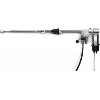
Indicator lamps Start up Operation Safety instructions 14 EN- 4 DANGERRisk to life on account of electric shock! Do not direct the water jet on the following equipment:– Electrical appliances and plants, – the unit itself, – all electricity-carrying parts in the working area. There is a recoil pressure arising from the water jet that comes out from the spray pipe. The angular spray pipe brings about an upward force. DANGER– Risk of injury! The recoil pressure of the spray pipe can throw you off-balance. You may fall. The spray jet can fly off and cause damage to persons. Search a secure place to stand and hold the gun firmly. Never hold on tightly to the lever of the hand spray gun.– The jet must not be directed at other persons or di-rected by the user at him/herself to clean clothing or footwear.– Risk of injury from parts flying off! Flying-off frag-ments or objects can injure people or animals. Nev-er direct the water jet on fragile or loose objects.– Risk of accident on account of damage! Clean tyres and valves from a minimum distance of 30 cm. DANGERDanger from substances that are harmful to health! Do not spray the following materials as they can swirl up substances that are harmful to health:– Materials containing asbestos,– Materials that could contain substances harmful to health. DANGER– Risk of injury on account of the emanating water jet that could be hot! Only original Kaercher high pres-sure hoses are optimally suited for the plant. No guarantee can be given if you use any other hoses.– Detergents can prove to be a health hazard! If any detergents are added, the water let out of the plant is not of potable quality.– Risk of hearing impairment while working on noise-making parts! If so, wear ear plugs.몇 WARNINGLong hours of using the appliance can cause circulation problems in the hands on account of vibrations.It is not possible to specify a generally valid operation time, since this depends on several factors:– Proneness to blood circulation deficiencies (cold, numb fingers).– Low ambient temperature. Wear warm gloves to protect hands.– A firm grip impedes blood circulation.– Continuous operation is worse than an operation interrupted by pauses.In case of regular, long-term operation of the device and in case of repeated occurrence of the symptoms (e.g. cold, numb fingers) please consult a physician. DANGERRisk of injury on account of the emanating water jet that could be hot! DANGERCheck the high pressure hose for damage before every use. Please arrange for the immediate replacement of a damaged high pressure hose. Check high pressure hose, pipe connections, fittings and water jet for damage every time before use. Check hose coupling to ensure that it sits firmly and is leak-proof. Turn the main switch to position “0”. Shut off water supply. Activate trigger gun until device is pressure-less. Open the water supply. Turn the main switch to position “1”. Press the unlocking key.Indicator lamp for operational readiness lights up. Perform the cleaning operation.Note: In case of a cleaning break of more than 30 sec-onds, the pump will turn off. At the same time, a 6-hour operation readiness period will be started. Within this operation readiness period, the appliance will automat-ically switch on because of the drop in pressure when the hand spray gun is opened. Press the unlocking key.Indicator lamp for operational readiness lights up. Turn the main switch to position “0”. Shut off water supply. Activate trigger gun until device is pressure-less. Secure the hand spray gun using the safety catch so that it doesn't open accidentally. If the appliance is not to be used for a longer period or if it is not possible to install it in a frost-free environment, you must take the following measures (see chapter "Maintenance and care", section "Anti-freeze protec-tion"): Drain water. Flush device with anti-freeze agent. Switch off the main switch and secure it.
dB(A)90909595 Hand-arm vibration valueHand spray gun m/s 3,63 3,63 3,63 3,63Spray lance m/s 7,52 7,52 7,52 7,52Uncertainty K m/s 1,0 1,0 1,0 1,0Exception according to Regulation (EU) 2019/1781 Annex I Section 2 (12): a) 15EN- 5 Illustration HDC 20/16 A High pressure connection(DN 15 - M22x1,5)B Water connection(3/4“, flat-sealing)몇 CAUTIONRisk of injury and damage! Observe the weight of the appliance when you transport it. When transporting in vehicles, secure the appli-ance according to the guidelines from slipping and tipping over.몇 CAUTIONRisk of injury and damage! Note the weight of the appli-ance in case of storage. Specifications sheet
Transport Storage 16 EN- 6 You can enter into a maintenance contract with the con- cerned Kaercher Sales Office for the machine. The machine should be stored in frost-free rooms. In case there is frosting risk, for e.g. if the machine is in- stalled in open areas, then the machine must first be emptied and flushed using an anti-freezing agent. Screw off water supply hose and high pressure hose. Operate device for max. 1 minute until the pump and conduits are empty. Note: Observe handling instructions of the anti-freeze agent manufacturer. Fill in normal anti-frost agents in the swimmer tank right until the top. Place the collection trough under the high pressure exit. Switch on the appliance and let it run until the safe- ty mechanism against lack of water in swimmer tank gets activated and the machine is switched off. A certain corrosion protection is achieved with this as well. DANGER Risk of injury! The main switch is to be switched off while carrying out any repairs or maintenance jobs. Error number display of the control – When an error is triggered, the operation readiness of the appliance is switched off and the pump is shut down. The control lamp "collection error" will blink in the pulse of the reported error number; or if the water level is low or the winding protection con- tact is triggered on the engine, the respective mes- sage lamp will illuminate. In addition to this, the er- ror number on the 7-segment display of the control unit will be displayed. – If one of the above errors occurs, the appliance can be restarted after the error has been corrected by activating the release switch. Care and maintenance DANGER Risk of injury! The main switch is to be switched off while carrying out any repairs or maintenance jobs. Maintenance schedule Time Activity Assembly affected Performance of whom daily Check hand-spray gun Hand spray gun Check whether the hand-spray gun closes tightly without any leaks. Check the protection mechanism against accidental switching. Replace defective hand-spray guns. Operator Check high pressure hoses Outlets, hoses towards working machine Check hoses to see if there are damages. Replace defect hos- es immediately. Danger of accident! Operator weekly or after 40 operat- ing hours Check the unit for leaks Entire plant Check pumps, overflow valve and pipe system for leaks. In- form Customer Service if there is oil below the pump or if there is a leakage of more than 3 drops of water per minute. Keep the leakage borings clear. Operator/Custom- er service Check oil level Oil level indicator on the pump If the oil is milky, it needs to be replaced. Operator Check oil level Oil level indicator on the pump Check oil level of the pump. Refill oil if required (Order no. 6.288-016) Operator monthly or after 200 oper- ating hours Check pump High-pressure pump Check the pump for leaks. If the leakage is more than 3 drops per minute, call Customer Service. Operator Check water scarcity fuse Swimmer switch in the swimmer tank Press the swimmer of the low water fuse down for about 5 sec- onds and control the error indicator on the control board. Re- move deposits if necessary. Operator Test swimmer valve Float tank The water level must be 40 mm below the overflow. No water must exit while the swimmer valve is closed. Operator Check overpump time. Controls Close consumer loads (e.g. hand spray guns). The pump must switch off after the afterrun period. Operator Test automatic start Pressure sensor The pump stands still as there is no water transfer. Open the hand spray gun. If the pressure in the high-pressure cycle falls below the switchpoint, the pump must switch on. Operator Tighten hose clips All hose clips Tighten the hose clips using a torque wrench. Tightening torque up to a diameter of 28 mm = 2Nm, from 29 mm = 6 Nm. Operator half-yearly or after 500 op- erating hours Oil change High-pressure pump Drain off oil. Fill in 1 l of fresh oil (order no. 6.288-016.0). Check the oil level at the oil level indicator. Operator half-yearly or after 1000 operating hours Check the appliance for calcium deposits entire water system Improper functioning of valves or pumps can be an indication of calcium deposits. If necessary decalcify. Operator trained in decalcification Tighten clamps Control board Tighten all clamps for components in the main circuit. Electrician Test swimmer valve Float tank The water level must be 40 mm below the overflow. No water must exit while the swimmer valve is closed. Customer Service annual Safety check Entire plant Safety check according to the guidelines for fluid spraying equipment. Technical expert Maintenance contract Frost protection Drain water Flush device with anti-freeze agent Troubleshooting Error num- ber Error description 01 Water shortage 02 Winding protection contact 03 Water temperature is too high 04 Leakage switch-off 1 (30 minutes of con- tinuous operation). 05 Leakage switch-off 2 (minor leakage) 06 Pressure sensor does not transmit signal 07 Temperature sensor does not transmit signal 08 ON switch continuously activated 17EN- 7 Fault Possible cause Remedy of whom Appliance is not running; indicator lamp for operations readiness is not illuminat-
There is no voltage in the machine. Check electrical mains. Electrician Main switch is switched off. Turn on the main switch. Operator Motor protection switch for the control and the prepressure pump has been triggered. Check motor protection switch. Customer Service Control board defective, green LEDs are not blinking. Check control board, replace if necessary. Customer Service Pump starts during the stand-by period and not when the hand spray gun is opened. Pressure sensor or cable to pressure sensor defective. Replace pressure sensor or cable. Customer Service Full pressure does not build up in the ap- pliance Flushed the nozzle. Replace the nozzle. Operator Suction site pipe leaking. Check screw fittings and hoses. Operator Safety valve is leaky. Check the setting; install new washers, if required. Customer Service Overflow valve is leaking or set too low. Check valve parts; replace damaged parts; clean the dirt. Customer Service Valve in the pump defective, high-pressure solenoid valve does not close. Replace defective components. Customer Service High pressure pump is knocking; ma- nometer is swaying wildly Pump is sucking air. Check suction system and remove leaks. Operator Valve plate or valve spring is defective. Replace defective components. Customer Service Advance pump calcified or defective. Check advance pump. Operator Overflow valve opens and closes contin- uously during 0 takeover Leakage in the high-pressure pipeline system or hand spray gun leaking. Locate and seal leakage. Operator Backflow valve or control piston seal leaking in overflow valve. Repair the overflow valve. Customer Service Indicator lamp "water low" is illuminated (error no. 01) The water shortage safeguard in the swimmer tank has got activated. Remove the water shortage. Operator Swimmer valve is jammed. Check swimmer valve for free movement. Operator Indicator lamp "engine overheated" is il- luminated (error no. 02) Thermal sensor in the engine or the over-cur- rent protection switch has been triggered. Rectify cause for over-loading. Customer Service Indicator lamp "collection error" is blink- ing (error no. 03) The temperature sensor in the swimmer tank has been activated. Reduce water infeed temperature. Operator Indicator lamp "collection error" is blink- ing (error no. 04) Leakage in the high-pressure pipeline sys- tem. Locate and seal leakage. Operator Too many consumer loads open at the same time. Close some consumer loads. Operator Flow switch defective. Replace flow switch. Customer Service Indicator lamp "collection error" is blink- ing (error no. 05) Leakage in the high-pressure pipeline sys- tem. Locate and seal leakage. Operator Flow switch defective. Replace flow switch. Customer Service Indicator lamp "collection error" is blink- ing (error no. 06) Pressure sensor does not transmit signal. Check pressure sensor, replace if required. Customer Service Indicator lamp "collection error" is blink- ing (error no. 07) Temperature sensor does not transmit signal. Check temperature sensor, replace if required. Customer Service Accessories Detergent Detergents simplify the cleaning tasks. The table gives a selection of detergents. Please read the instructions on the packaging carefully before working with any detergents. Area of application Target group Detergent Kärcher description Dosaging in high pres- sure Foaming Food industry/disassembly facilities Disinfection cleaning RM 732 1-3% Disinfectant RM 735 0,75-7% Foam disinfecting detergent, alkali-based RM 734 2-5% Beverage facilities/wine cellars Foam detergent, alkali-base RM 58 ASF 1-2% Foam cleaner, acidic RM 59 ASF 1-2% Foam disinfecting detergent, alkali-based RM 734 2-5% Community Exterior foam cleaner, neutral RM 57 1-2% Disinfecting cleaner, inside RM 732 1-3% Agriculture Disinfection cleaning RM 732 1-3% Disinfectant RM 735 0,75-7% High-pressure cleaning Beverage facilities/wine cellars Universal cleaner RM 55 0,5-8% Foam disinfecting detergent, alkali-based RM 734 2-5% Community Active cleanser, alkali-based RM 81 1-5% Agriculture Active cleanser, alkali-based RM 31 1-5% Active cleanser, alkali-based RM 81 1-5% Ship equipment Active cleanser, alkali-based RM 81 1-5% Automotive/lorry workshop Active cleaner, alkali-based (engine/parts) RM 31 1-5% Active cleaner, alkali-based (vehicle, top and bottom wash) RM 81 1-5% Floor cleaning Food industry/disassembly facilities Intensive basic cleaner RM 750 1-5% Floor basic cleaner RM 69 0,5-1% Beverage facilities/wine cellars, community Intensive basic cleaner RM 750 1-5% Floor basic cleaner RM 69 0,5-1% Automotive/lorry workshop Intensive basic cleaner RM 750 1-5% Floor basic cleaner RM 69 0,5-1% Ship equipment Intensive basic cleaner RM 750 1-5% Floor basic cleaner RM 69 0,5-1% Washing brush Community Exterior active cleanser, alkali-based RM 81 1-5% Universal cleaner RM 55 0,5-8% Automotive/lorry workshop Active cleaner, alkali-based (vehicle, top and bottom wash) RM 81 1-5% Ship equipment Exterior active cleanser, alkali-based RM 81 1-5% 18 EN- 8 – Before installing, please check the load-bearing ca-pacity of the wall. Use suitable anchor plugs and screws for concrete walls, hollow component walls, brick walls and gas concrete walls - for e.g. injec-tion anchors (see packaging for drilling template).– The appliance should not be directly attached to the network of water and high pressure pipes. It is mandatory to install the connecting hoses. – A shut-off tap must be installed between the main water supply and the connecting hose. All national laws and regulations about installation of electrical appliances must also be followed when install-ing high pressure lines.– The pressure loss in the pipe connections must lie below 1.5 MPa. – The completed pipeline must be tested with 16 MPa (HDC 20/8) bzw. 32 MPa (HDC 20/16).– The insulation of the pipes must be resistant to temperatures until 100 °C.ATTENTIONRisk of damage to the plant if water supply is not of suit-able quality.Note: Impurities in the inlet water can damage the unit. Kärcher recommends a water filter with a mesh width of <80µm.Quality requirements for tap water: * Test volume 1litre, Settling time 30 minutes** decalcification measures are necessary if the values are higher The water inlet is to be connected to the main water supply using a water hose.– The water supply must have a minimum output of 2,000 l/h at minimum 0.15 MPa.– Appliances without prepressure pump: The water temperature must lie below 60 °C.– Machines with prepressure pump: The water tem-perature must lie below 85 °C.Note: Operating procedures create short term power sinkings. During unfavorable net conditions other devic-es might be disturbed.ATTENTIONThe highest allowed net impedance at the electrical connection point (refer to technical data) is not to be ex-ceeded. In case of confusion regarding the power im-pedance present on your connection, please contact your utilities provider.– For connection values, see technical data and type plate.– The electrical connections must be done by an electrician according to IEC 60364-1. – Current-carrying parts, cables and appliances in the working area must be installed in a defectless state and must be protected against water sprays. DANGERTo avoid accidents due to electrical faults we recom-mend the use of sockets with a line-side current-limiting circuit breaker (max. 30 mA nominal tripping current).The appliance is factory set to a pressure of 8 MPa (HDC 20/8) or 14 MPa (HDC 20/16).1 Adjustment screw for high pressure2 Lock nut for high pressure3 Spindle of the pressure/quantity regulation4 Adjustment screw for low pressure5 Locknut for low pressure6 Housing of the overflow valve Fasten the test manometer (part no. 4.742-025) to the high-pressure connection. Connect the high-pressure hose with the servo press hand spray gun to the test manometer. Rotate the servo press to the "MIN" position, open the hand spray gun and let the device run. Rotate the spindle of the pressure/quantity regula-tion to the stop. Loosen the locknut for high pressure. Turn the adjustment screw high pressure so that the opening pressure of the overflow valve plus 1.5 MPa is reached on the test manometer.Note: If this screw is turned clockwise, the pressure is increased; and if it is turned counter-clockwise, the pressure is decreased. Secure the adjustment screw for high pressure with the locknut. Check working pressure and delivery rate. Seal the adjustment screw for high pressure and the lock nut with locking paint.We hereby declare that the machine described below complies with the relevant basic safety and health re-quirements of the EU Directives, both in its basic design and construction as well as in the version put into circu-lation by us. This declaration shall cease to be valid if the machine is modified without our prior approval.5.957-926The signatories act on behalf of and with of the authority of the company management.Documentation supervisor:S. ReiserAlfred Kärcher SE & Co. KGAlfred-Kärcher-Straße 28-4071364 Winnenden (Germany)Tel.: +49 7195 14-0Fax: +49 7195 14-2212Winnenden, 2021/02/01The warranty terms published by our competent sales company are applicable in each country. We will repair potential failures of the appliance within the warranty period free of charge, provided that such failure is caused by faulty material or defects in fabrication. Installing the plant Only for authorised technicians! Wall mount Installing the high pressure connections Water supply pH value 6,5...9,5electrical conductivity < 2000 µS/cmremovable materials < 0,5 mg/l *filterable materials (grain size be-low 0.025 mm)< 20 mg/lHydrocarbons < 20 mg/lChloride < 300 mg/lCalcium < 85 mg/l **Total hardness < 9 °dH **Iron < 0,5 mg/lManganese < 0,05 mg/lCopper < 0,02 mg/lfree of bad odours
www.kaercher.com/REACH