AWTC - Pressure washer Kärcher - Free user manual and instructions
Find the device manual for free AWTC Kärcher in PDF.
Download the instructions for your Pressure washer in PDF format for free! Find your manual AWTC - Kärcher and take your electronic device back in hand. On this page are published all the documents necessary for the use of your device. AWTC by Kärcher.
USER MANUAL AWTC Kärcher
1. In the event of an emergency, push the
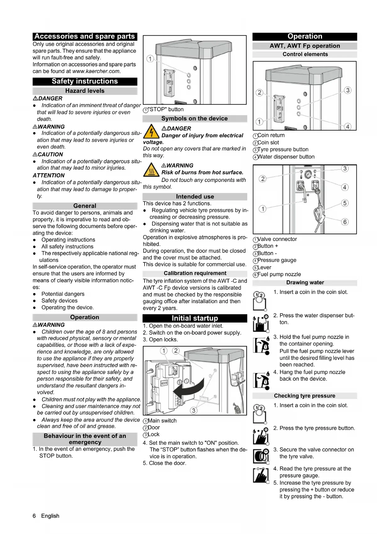
STOP button. 1 "STOP" button Symbols on the device DANGER Danger of injury from electrical voltage. Do not open any covers that are marked in this way. 몇WARNING Risk of burns from hot surface. Do not touch any components with this symbol. Intended use This device has 2 functions. ● Regulating vehicle tyre pressures by in- creasing or decreasing pressure. ● Dispensing water that is not suitable as drinking water. Operation in explosive atmospheres is pro- hibited. During operation, the door must be closed and the cover must be attached. This device is suitable for commercial use. Calibration requirement The tyre inflation system of the AWT -C and AWT -C Fp device versions is calibrated and must be checked by the responsible gauging office after installation and then every 2 years. Initial startup
1. Open the on-board water inlet.
2. Switch on the on-board power supply.
4. Set the main switch to "ON" position.
The “STOP” button flashes when the de- vice is in operation.
1. Insert a coin in the coin slot.
2. Press the water dispenser but-
3. Hold the fuel pump nozzle in
the container opening. Pull the fuel pump nozzle lever until the desired filling level has been reached.
4. Hang the fuel pump nozzle
1. Insert a coin in the coin slot.
2. Press the tyre pressure button.
3. Secure the valve connector on
4. Read the tyre pressure at the
5. Increase the tyre pressure by
pressing the + button or reduce it by pressing the - button.English 7 AWT -C, AWT -C Fp operation Control elements 1 Coin return 2 Coin slot 3 Tyre pressure button 4 Water dispenser button 1 Fuel pump nozzle 2 Lever 3 Valve connector 4 Target pressure display 5 Tire pressure display 6 Button + 7 Button - 8 Flat tyre button 9 No function Drawing water Checking tyre pressure Filling flat tyres If the tyre has no pressure, the device can- not detect that the valve connector has been connected to the valve. Settings Setting the run time Note The adjustable run time applies to the in- sertion of one of the following coins: ● 50 Eurocents ● 50 British pence ● 1 Swiss franc ● 1 Polish złoty ● 5 Norwegian Kroner Customer Service can set up different types of coins.
1. Set the run time with the P I rotary knob.
Possible setting range of 30 seconds to 7 minutes. 1 Rotary knob P I Note Rotary knobs P II, P III and P IV have no function. Frost protection Device with frost protection
1. Turn the frost protection switch "ON" at
temperatures below +5°C. 1 Frost protection switch 2 Frost protection heater ATTENTION Risk of damage The frost protection is active only when the main switch is “ON”. When activating the frost protection, check whether the main switch is in the “ON” po- sition. Note The frost protection heater is not thermo- stat-controlled. When switched on, the heater is continuously in use. Device without frost protection In a device without frost protection, a shut- down must be carried out if there is risk of frost. Shutting down
1. Close the water inlet
2. Drain the condensate in the compressed
air tank (see "Maintenance tasks").
3. Set the main switch to the "OFF" posi-
tion. Shutdown in the case of potential frost
1. Close the water inlet.
2. Remove water from the device and sup-
pressed air tank (see “Maintenance work”).
4. Set the main switch in "OFF" position.
6. Remove the valve connector.
7. Pull on the hose briefly and
feed the hose in via the auto- matic hose reel.
1. Insert a coin in the coin slot.
2. Press the water dispenser but-
3. Hold the fuel pump nozzle in
the container opening. Pull the fuel pump nozzle lever until the desired filling level has been reached.
4. Hang the fuel pump nozzle
1. Insert a coin in the coin slot.
with the + and - buttons in the target pressure display (upper display).
4. Secure the valve connector on
the tyre valve. The tyre pressure display (low- er display) shows the tyre pres- sure.
5. Wait until an acoustic signal in-
dicates that the tyre target pres- sure has been reached.
6. Remove the valve connector.
7. Pull on the hose briefly and
feed the hose via the automatic hose reel.
1. Insert a coin in the coin slot.
with the + and - buttons in the target pressure display (upper display).
4. Secure the valve connector on
6. Wait until an acoustic signal in-
dicates that the tyre target pres- sure has been reached.
7. Remove the valve connector.
8. Pull on the hose briefly and
feed the hose via the automatic hose reel.8 English Care and service Daily
1. Empty the coin cassette (see "Mainte-
2. Check the general condition of the de-
3. Check the condition of the valve connec-
4. Check the condition of the hose lines.
5. Open the lower cover and check the
condition of the compressor.
6. Have damaged parts replaced.
1. Clean the outside of the device.
2. Drain the condensate in the compressed
air tank (see "Maintenance tasks"). ATTENTION Risk of damage The water in the compressed air line can damage the tyre pressure sensor. Drain the condensate in the compressed air tank regularly. Service very 2 years Only with AWT -C, AWT -C Fp
1. Have the pressure measuring device of
the tyre inflator calibrated by the gauging office. Maintenance work Emptying the coin cassette
1. Remove the cover.
1 Bar cover 2 Condensate drain valve
2. Hold the condensate drain valve over a
shaft or collecting container. 몇 WARNING Risk of injury, risk of damage The water stream escaping from the con- densate drain valve can cause injury or damage. Never point the condensate drain valve at people, animals, the device or electrical components.
3. Slowly open the condensate drain valve
5. Attach the cover.
Transport 몇 CAUTION Risk of injury, risk of damage Be aware of the weight of the device during transportation.
1. When transporting in vehicles, secure
the device against slipping and tipping over according to the applicable guide- lines. Storage 몇 CAUTION Risk of injury and damage Be aware of the weight of the device during storage. Troubleshooting guide DANGER Danger from electric shock. Before working on the device, set the main switch to “OFF” and disconnect the on- board power supply. The device does not work Check the on-site voltage supply. Set the main switch to "ON" position. Contact customer service. The device does not start after the valve connector has been connected to the tyre. Check that the valve connector is seated correctly. Check the condition of the hose and of the valve connector. Press the “tyre flat” button. There is no compressed air Pull the compressor on-button upward. 1 Compressor on-button The compressor is overheated: Wait un- til the compressor has cooled off. The tyre pressure is too low Check the pressure on the pressure gauge. Readjust the pressure reducer if necessary. 1 Pressure reducer 2 Pressure gauge Malfunctions with information shown on the display Fault Cause Rectification ER1 Unstable pressure measurement due to defective valve connector or hose Replace the valve connector. Replace the hose. ER2, ER7 The tyre pressure is too low. Unstable pressure measurement due to defective valve connector or hose. Check the tyre pressure on the pressure gauge and re- adjust the pressure reducer if necessary. Replace the valve connector. Replace the hose. ER3 The tyre pressure is too low. Check the pressure on the pressure gauge and read- just the pressure reducer if necessary. ER4 The tyre pressure is too high. Check the pressure on the pressure gauge and read- just the pressure reducer if necessary. ER5 The voltage supply is disturbed. Contact customer service. ER6, ER8, ER9, ERU, ERB Malfunction in the electronics. Contact customer service. ERP The valve connector came loose during in- flation. The tyre pressure is not stable. Check that the valve connector is seated correctly. Check the pressure on the pressure gauge and read- just the pressure reducer if necessary.Français 9 Warranty The warranty conditions issued by our rele- vant sales company apply in all countries. We shall remedy possible malfunctions on your appliance within the warranty period free of cost, provided that a material or manufacturing defect is the cause. In a war- ranty case, please contact your dealer (with the purchase receipt) or the next author- ised customer service site. (See overleaf for the address) Technical data Subject to technical modifications. EU Declaration of Conformity We hereby declare that the machine de- scribed below complies with the relevant basic safety and health requirements in the EU Directives, both in its basic design and construction as well as in the version placed in circulation by us. This declaration is invalidated by any changes made to the machine that are not approved by us. Product: Tyre inflator Type: AWT, AWT Fp, AWT -C, AWT -C Fp Currently applicable EU Directives 2006/42/EC 2014/35/EU 2014/30/EU Documentation supervisor: Gianmarco Stra MTM Hydro Srl Via Moglia, 33 12062 Cherasco (Cn) - Italy Tel. +39 0172 427311 Fax +39 0172 495437