C500 - Car stereo Auna - Free user manual and instructions
Find the device manual for free C500 Auna in PDF.

User questions about C500 Auna
0 question about this device. Answer the ones you know or ask your own.
Ask a new question about this device
Download the instructions for your Car stereo in PDF format for free! Find your manual C500 - Auna and take your electronic device back in hand. On this page are published all the documents necessary for the use of your device. C500 by Auna.
USER MANUAL C500 Auna
Automotive Qualification
Amplification 100%
Ampl 2017
10032
au
www.auna-multimedia.com

text_image
QR code image containing encoded data, no visible human-readable textINHALTSVERZEICHNIS
Technische Daten 4
natural_image
3D illustration of a red corrugated metal component with multiple screws attached (no text or symbols)FUNKTIONEN
Member of Berlin Brands Group
Handwerkerstr. 11
15366 Dahlwitz-Hoppegarten
Deutschland
natural_image
Symbol of a trash bin crossed with a diagonal line, no text or numbers presentCongratulations on the purchase of your appliance. Please read the following instructions carefully and follow them to prevent potential damage. We accept no liability for damage caused by disregarding the instructions or improper use. Please scan the QR code to access the latest operating instructions and for further information about the product.

text_image
QR code image containing encoded data, no visible human-readable textCONTENTS
Technical Data 22
Safety Instructions 22
Connections 24
Circuit 25
Car radio connection and loudspeaker connection 26
Loudspeaker connection 28
Power supply 31
Assembly 31
Functions 32
Troubleshooting 34
Disposal Considerations 35
Declaration of conformity 35
TECHNICAL DATA
| Item number 10032117 10032118 | 100321119 | ||
| Outputs 2 channels 4 channels | 6 channels | ||
| Max. Output power 1000 W 20 | 00 W 3000 W | ||
| High pass 50 Hz - 500 Hz | |||
| Low pass 50 Hz - 250 Hz | |||
| Signal-to-noise ratio 90 dB | |||
| Frequency response 10 Hz - 30 kHz | |||
| Input sensitivity 120 mV - 1.0 V | |||
| Impedance Signal-to-noise ratio | |||
| Load impedance 2 - 8 Ω | |||
| Attenuation factor | >120 | ||
| Bass boost | (50 Hz) 0/+6/+12 dB | ||
| Power supply | 10.5 - 15 V | ||
| Dimensions (mm) | 200 x 250 x 52 | 200 x 280 x 52 | 350 x 250 x 52 |
SAFETY INSTRUCTIONS
Power supply
- Do not connect the +12 V power cable until all other cables are connected.
- Make sure that the unit's earth wire is securely connected to a metal point on the vehicle.
- If you are using the car radio without the remote output to the amplifier, connect the remote input terminal (REM OTE) to the power supply accessory.
• Use the power cable with an attached fuse (40 A). - Ensure that the cables to the +12 connection and earth connection have a larger cross-section than 5 mm ^4 .
General Safety Instructions
- This device is only suitable for connection to a 12 V power supply.
- Use speakers with a suitable impedance (2-16 ohms, stereo).
- Do not connect active speakers (with built-in amplifier).
-
Do not mount the amplifier in areas where it will be
-
exposed to high temperatures (e.g. due to direct sunlight or heating).
• exposed to rain or moisture. -
exposed to dust or dirt.
-
If the car is parked in direct sunlight and the temperature in the car rises considerably, allow it to cool down before use.
- When installing the device horizontally, make sure to cover the ribs with a carpet or similar.
- If the power amplifier is mounted too close to the car radio, interference may occur. In this case, place the amplifier further away from the radio.
- If the device is not supplied with power, check the connections.
- The amplifier uses circuit protection to protect the transistors and speakers in the event of a malfunction. Do not attempt to test the circuit protection by covering the heat sink or electrically overloading the device.
- Do not use the amplifier with a weak car battery, as optimum performance depends on a good power supply.
- Keep the volume at a moderate level so that you can still hear the sounds outside your vehicle.
Circuit protection
This amplifier is equipped with a protection that works in the following cases:
- The device is overheated.
• Alternating current is generated. - The loudspeaker connections have a short circuit.
The emergency stop light lights up when the device shuts down. If this happens, switch off the connected device and find out the reason for the malfunction. If the amplifier has overheated, wait until the device has cooled down again before switching it on again.
CONNECTIONS
Before connecting, note the following
- Before connecting, take the earth off the car battery to avoid short circuits.
- Make sure that the speakers have the appropriate power. If you connect speakers with insufficient power rating, they may be damaged.
- Do not connect the "- clamps" of the speakers to the body of the car and also connect the "- clamp" of the right speaker to that of the left speaker.
- Place the input and output cables away from the power supply lead, otherwise interference will occur.
- This device is a powerful amplifier. Therefore, it cannot reach its full potential when operated with the pre-installed cables of the car speakers.
- If your car is equipped with a computer/navigation system, do not disconnect the ground from the car battery as this could erase the computer memory. To avoid short circuits when making connections, disconnect the lead for the 12 V power connection until all other connections have been made.
Replacing the fuse
- If the fuse is blown, check the power connections and insert a new fuse. If the fuse blows again after replacement, there may be an internal malfunction. In this case, contact a workshop.
- The new fuse must match the amplifier and correspond to the specifications on the fuse holder. Never use a fuse with a current rating that exceeds the specifications of the appliance fuse, otherwise the appliance could be damaged.
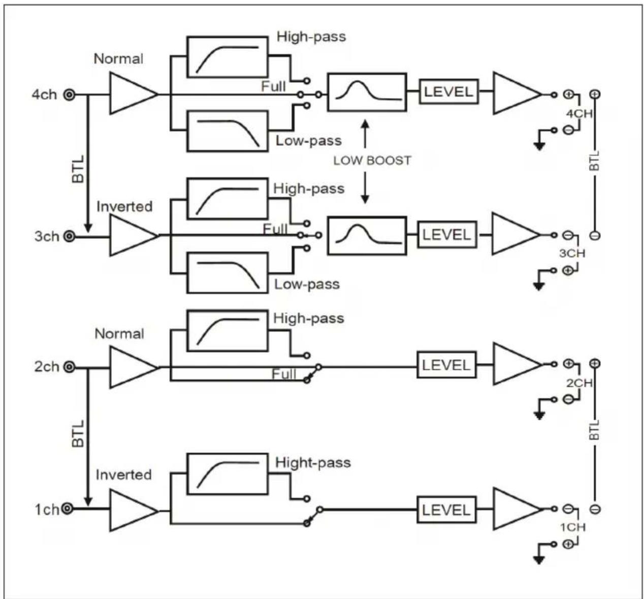
CIRCUIT
flowchart
graph TD
    A["4ch"] --> B["Normal"]
    B --> C["High-pass"]
    C --> D["Full"]
    D --> E["LEVEL"]
    E --> F["+"]
    F --> G["4CH"]
    G --> H["BTL"]
    I["3ch"] --> J["Inverted"]
    J --> K["High-pass"]
    K --> L["Full"]
    L --> M["LEVEL"]
    M --> N["+"]
    N --> O["3CH"]
    O --> P["BTL"]
    Q["2ch"] --> R["Normal"]
    R --> S["High-pass"]
    S --> T["Full"]
    T --> U["LEVEL"]
    U --> V["+"]
    V --> W["2CH"]
    W --> X["BTL"]
    Y["1ch"] --> Z["Inverted"]
    Z --> AA["High-pass"]
    AA --> AB["Full"]
    AB --> AC["LEVEL"]
    AC --> AD["+"]
    AD --> AE["1CH"]
    AE --> AF["BTL"]
    style A fill:#f9f,stroke:#333
    style I fill:#f9f,stroke:#333
    style Q fill:#f9f,stroke:#333
    style Y fill:#f9f,stroke:#333
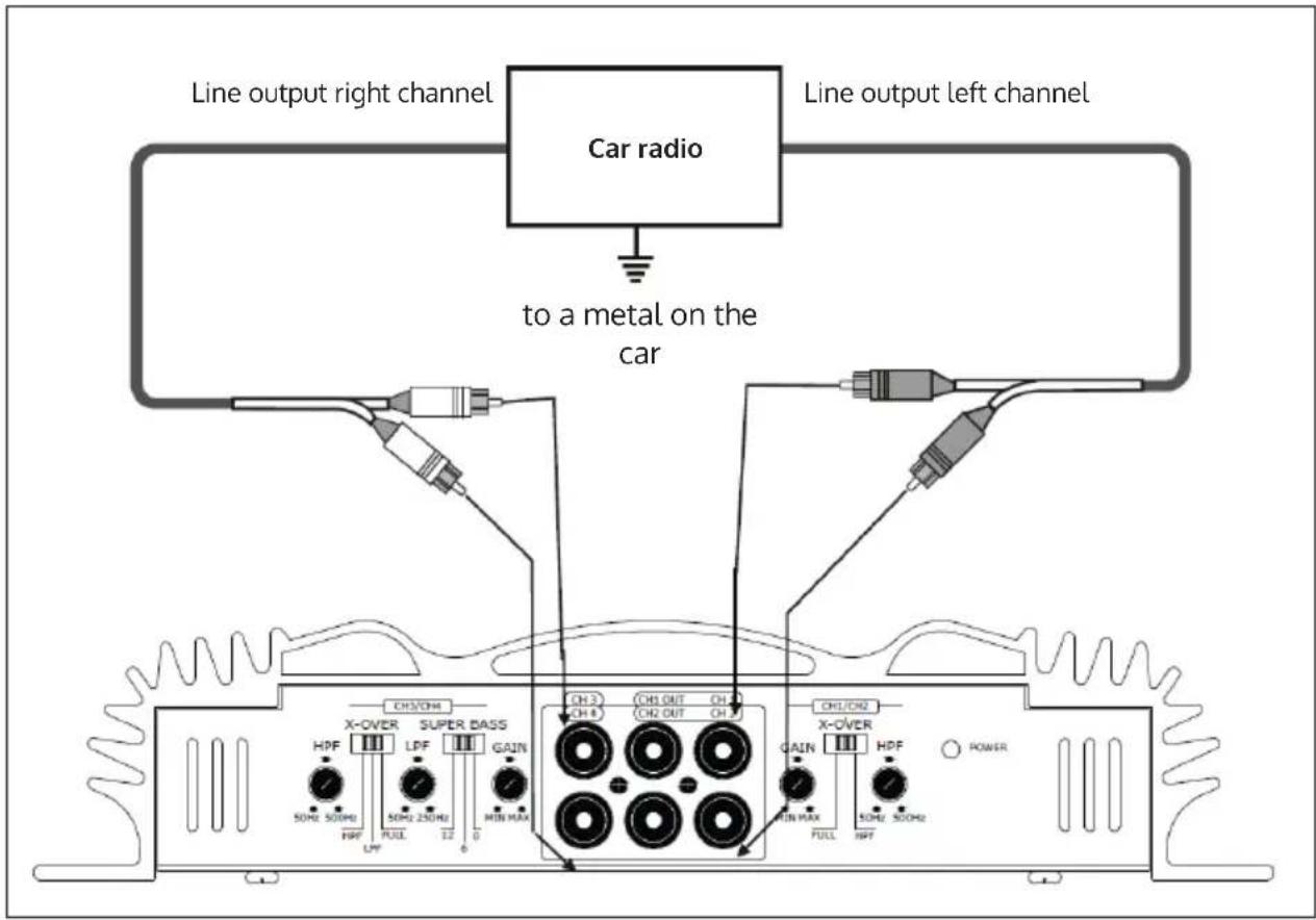
CAR RADIO CONNECTION AND LOUDSPEAKER CONNECTION
For 3-channel connection
text_image
Line output right channel Car radio Line output left channel to a metal on the car CHS/CH4 X-OVER SUPER BASS HDF LDF GAIN SOHE SOHEI LPF FUEL 12 0 CH3 CH8 CH1 OUT CH2 OUT CH3 CHL/CH4 X-OVER HDF POWER GAIN IN MAX FULL HFFFor 2/4/6-channel connection
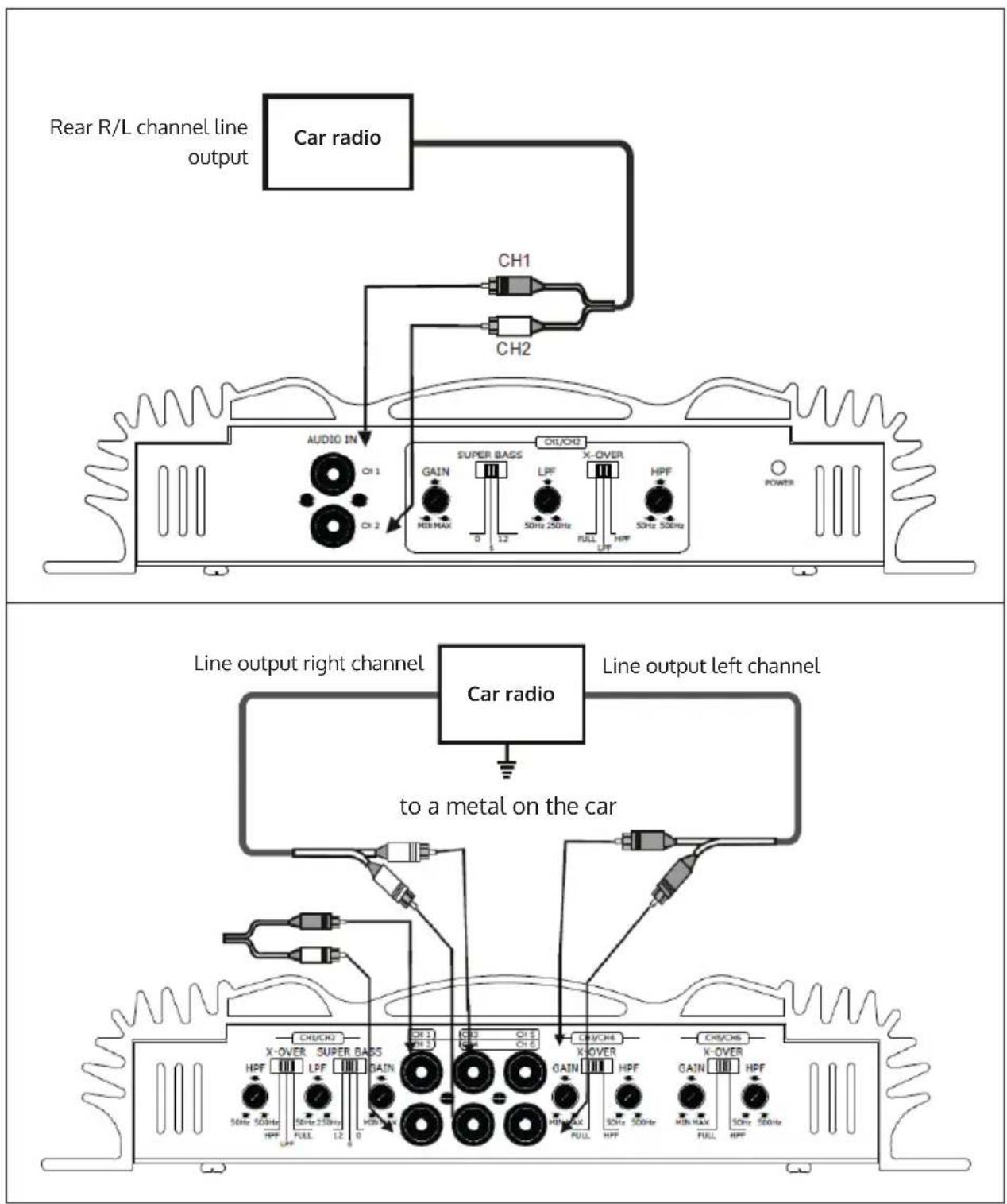
text_image
Rear R/L channel line output Car radio CH1 CH2 AUDIO IN CH1 Super BADS GAIN LPF X-OVER HPF M8MAX 0 12 50Hz 250Hz FULL LPF 50Hz 300Hz POWER Line output right channel Car radio Line output left channel to a metal on the car CH/CH4 X-OVER SUPER BADS HPF LPF GAIN 50Hz 500Hz 50Hz 250Hz HPF FULL 12 0 CH/CH4 X-OVER K-Over HPF GAIN HPF 50Hz 500Hz KIN MAX FULL HPFLOUDSPEAKER CONNECTION
4-channel connection
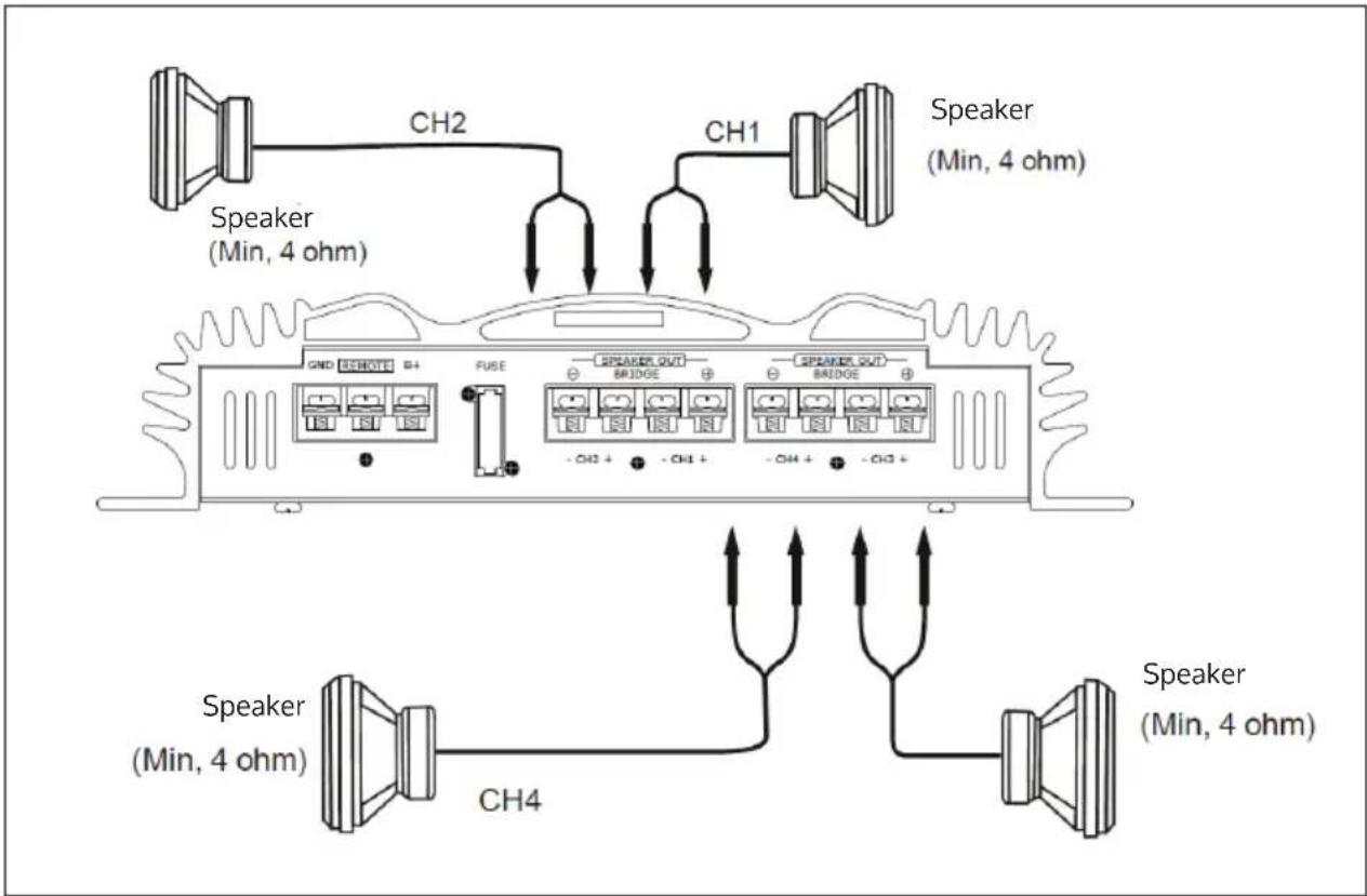
text_image
Speaker (Min, 4 ohm) CH2 CH1 Speaker (Min, 4 ohm) GND BHD015 B+ FUSE SPEAKER OUT BRIDGE SPEAKER OUT BRIDGE - CH2 + - CH1 + - CH4 + Speaker (Min, 4 ohm) CH4 Speaker (Min, 4 ohm) Speaker (Min, 4 ohm)3-channel connection
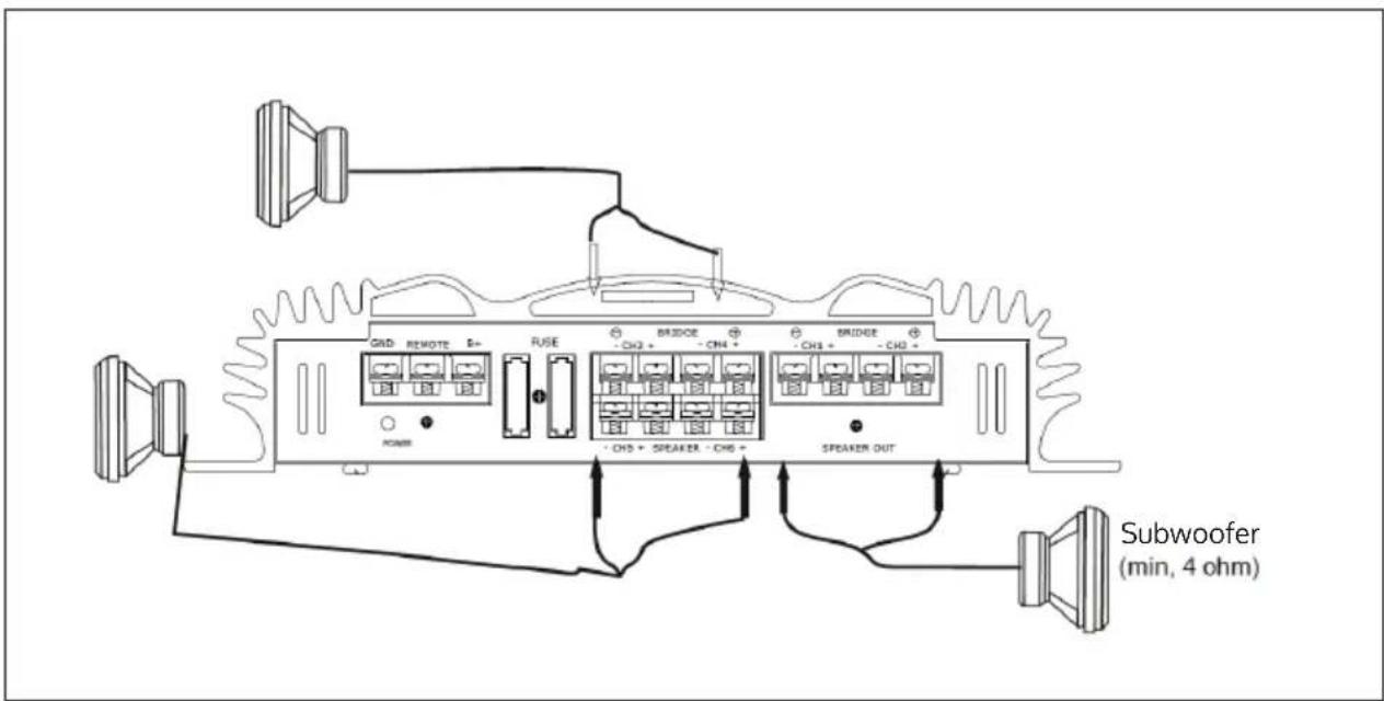
text_image
GND REMOTE S+ FUSE BRIDGE - CH3 + - CH4 + BRIDGE - CH3 + - CH4 + POWER - CH5 + SPEAKER - CH6 + SPEAKER OUT Subwoofer (min, 4 ohm)Note: In this configuration, the volume of the subwoofer is controlled by the fader of the car radio. The output signal to the subwoofer is a combination of the REAR L and R inputs or the high-level REAR input.
2-channel connection
For details on the settings of the switches and controls, see "Functions".
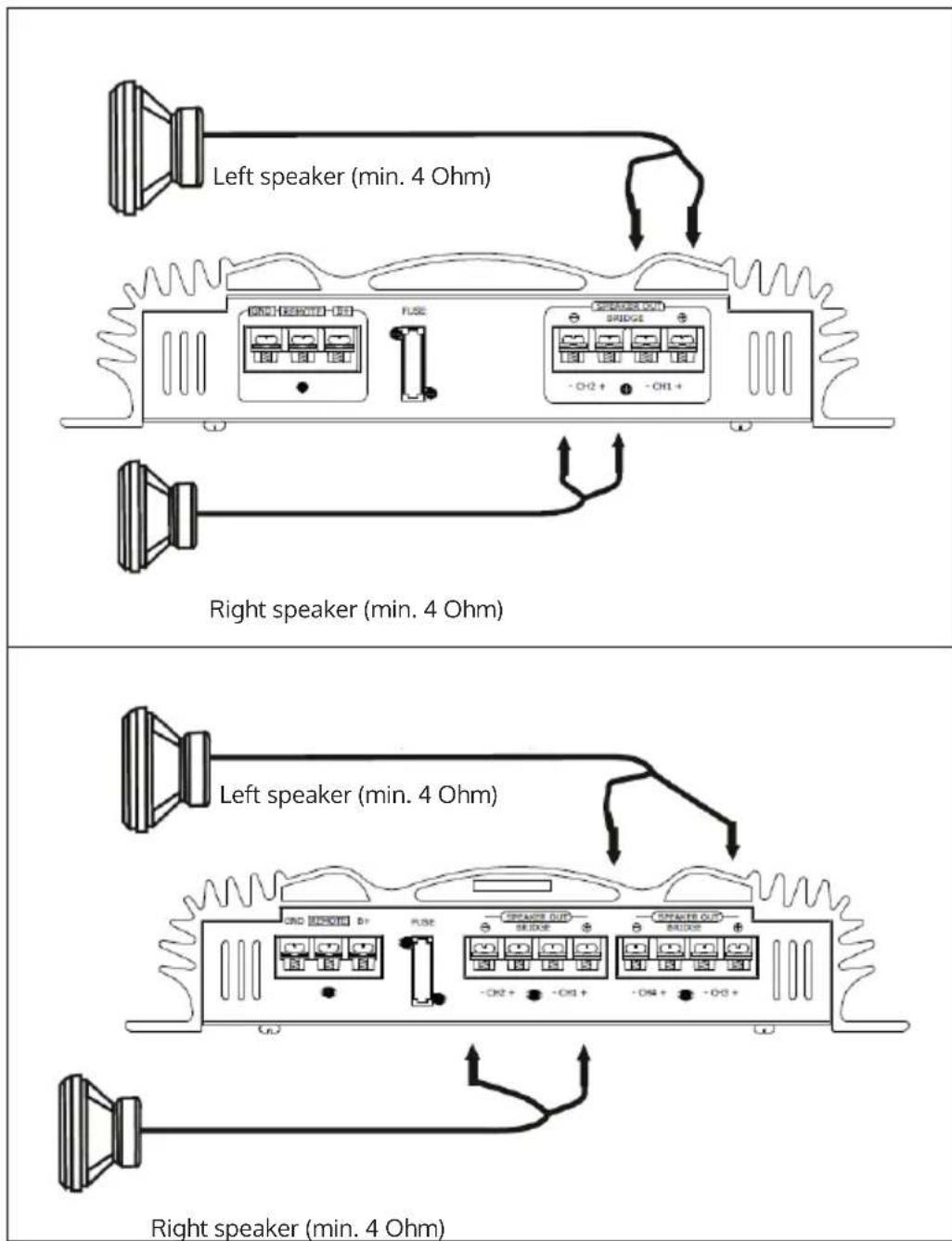
text_image
Left speaker (min. 4 Ohm) Right speaker (min. 4 Ohm) Left speaker (min. 4 Ohm) Right speaker (min. 4 Ohm)6-channel connection
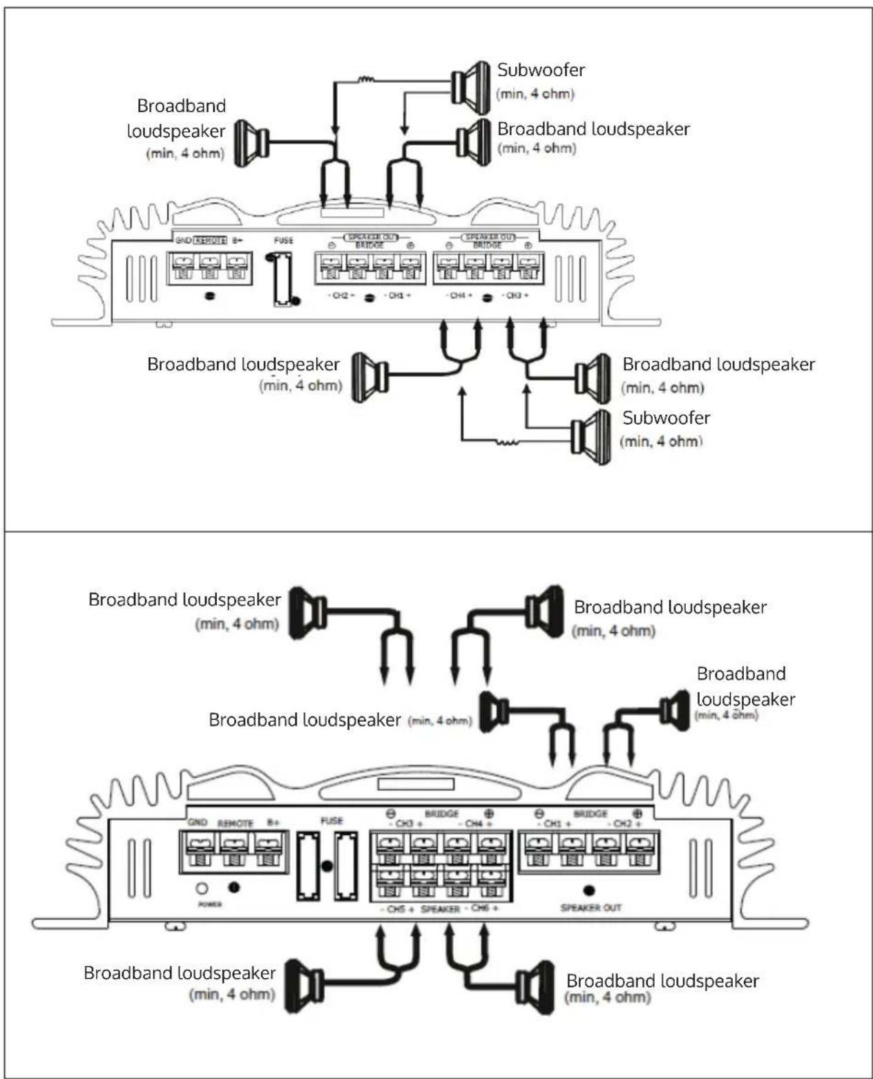
text_image
Broadband loudspeaker (min, 4 ohm) Subwoofer (min, 4 ohm) Broadband loudspeaker (min, 4 ohm) GND REMOTE B+ FUSE SPREAD OUT BRIDGE SPEAKER OUT BRIDGE -CH2+ -CH1+ -CH4+ -CH3+ Broadband loudspeaker (min, 4 ohm) Broadband loudspeaker (min, 4 ohm) Subwoofer (min, 4 ohm) Broadband loudspeaker (min, 4 ohm) Broadband loudspeaker (min, 4 ohm) Broadband loudspeaker (min, 4 ohm) Broadband loudspeaker (min, 4 ohm) GND REMOTE B+ FUSE BRIDGE -CH3+ -CH4+ -CH5+ -CH6+ SPEAKER OUT POWER Broadband loudspeaker (min, 4 ohm) Broadband loudspeaker (min, 4 ohm)Note: In this configuration, the volume of the subwoofer is controlled by the fader of the car radio.
POWER SUPPLY
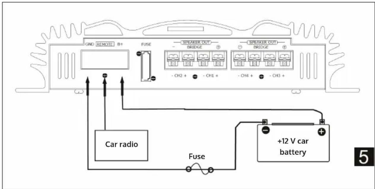
text_image
GND REMOTE B+ FUSE SPEAKER OUT BRIDGE SPEAKER OUT BRIDGE - CH2 + - CH1 + - CH4 + - CH3 + Car radio Fuse +12 V car battery 5ASSEMBLY
Before the assembly
- Mount the device either in the boot or under a seat.
- Choose the mounting location carefully so that the device does not interfere with the driver's everyday movements and is not exposed to direct sunlight or hot air from the heater.
- Do not install the device under a carpet where heat dissipation from the device is significantly affected.
Assembly
Place the box where you want to mount it and mark the four drill holes on the mounting board (not included). Drill holes with a diameter of approx. 3 mm. Screw the device on with the enclosed screws (15 mm). Make sure that the board is at least 15 mm thick.
Note: Tighten the screws firmly but do not use too much force. The torque should be less than 1 Nm.
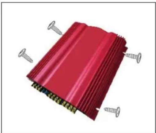
natural_image
3D rendering of a red corrugated metal component with multiple screws attached (no text or symbols visible)FUNCTIONS
| 1 | Operating display |
| Lights up green during operation. | |
| 2 | Protection control lamp |
| Overvoltage: lights up red in case of overvoltage or short circuit | |
| Offset: lights up when the voltage to the speaker terminals is too high. | |
| Thermal: lights up when the temperature is too high. | |
| 3 | Filter selector switch |
| When the switch is set to LPF, the filter is set to low pass. When the switch is set to HPF, the filter is set to high-pass. | |
| 4 | Crossover separation controller |
| Controls the crossover separation for the low pass filter. | |
| 5 | Low boost control |
| To increase the frequencies from 50 Hz to a maximum of 12 dB. | |
| 6 | Level control |
| The input level can be adjusted when using the input sources of other manufacturers. | |
| 7 | Crossover separation controller |
| Controls the crossover separation for the high pass filter |
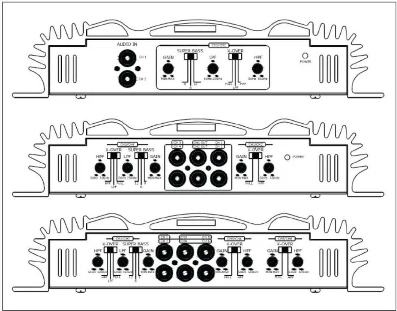
text_image
AUDIO IN CH 1 CH 2 SUPER BASS GAIN MIN/MAX 0 12 50Hz 250Hz LPF FULL HPF 50Hz 500Hz X-OVER POWER CH3/CH3 GAIN MIN/MAX 50Hz 500Hz SOM2 500Hz SOM2 250Hz FULL 12 0 6 CH3/CH3 X-OVER SUPB. BASS LPF GAIN MIN/MAX ON 3 CH 4 CH 5 OUT CH 6 OUT ON 3 CH 7 OUT CH 8 OUT CH3/CH3 X-OVER GAIN MIN MAX FULL HPF POWER CH3/CH3 X-OVER SUPB. BASS LPF GAIN MIN/MAX ON 3 CH3 CH4 OUT CH 4 OUT ON 3 CH3/CH4 X-OVER GAIN MIN/MAX FULL HPF POWER CH3/CH3 X-OVER SUPB. BASS LPF GAIN MIN/MAX ON 3 CH3/CH4 OUT CH 4 OUT ON 3/CH3/CH4 OUT X-OVER GAIN MIN/MAX FULL HPF POWERTROUBLESHOOTING
| Problem Possible cause and solution | |
| The power indicator does not light up. | The fuse is loose or blown. Tighten the fuse or replace the fuse with a new one. |
| The earth lead is not connected correctly. Attach it to a metal point in the car. | |
| The control unit is not switched on. Turn on the control unit. | |
| The system uses too many amplifiers. Use a relay. | |
| Check the battery voltage (10.5-15 V). | |
| The audio output is switched off. The power indicator lights up red. | The loudspeaker connections are short-circuited. Turn off the on/off switch. Fix the cause of the short circuit. |
| Noise from the alternator. The power supply cables are routed too close to the cinch cables. Clean the wiring and move the power supply cables further away from the audio cables. | |
| The sound is muffled. The filter must be set to the LPF position. | |
| The sound is too low. Move the level control to the MIN position. Set it up higher. | |
DISPOSAL CONSIDERATIONS

natural_image
Symbol of a trash bin crossed with a diagonal line, no text or numbers presentIf there is a legal regulation in your country regarding the disposal of electrical and electronic equipment, this symbol on the product or on the packaging indicates that this product must not be disposed of with household waste. Instead, it must be taken to a collection point for the recycling of electrical and electronic equipment. By disposing of this product in accordance with the regulations, you protect the environment and the health of those around you from negative consequences. For information on recycling and disposal of this product, contact your local government or household waste disposal service.
This product contains batteries. If there is a legal regulation in your country regarding the disposal of batteries, the batteries must not be disposed of in household waste. Consult your local regulations for the disposal of batteries. By disposing of this product in accordance with the regulations, you are protecting the environment and the health of those around you from negative consequences.
DECLARATION OF CONFORMITY

text_image
CE UK CAManufacturer:
Chal-Tec GmbH, Wallstraße 16, 10179 Berlin, Germany.
Importer for Great Britain:
Berlin Brands Group UK Ltd
PO Box 1145
Oxford, OX1 9UW
United Kingdom
The complete manufacturer's declaration of conformity can be found at the following link:
https://use.berlin/10032119
Cher client, chère cliente,
text_image
QR code image containing encoded data, no visible human-readable textSOMMAIRE
Fiche technique 38
natural_image
3D rendering of a red corrugated metal component with multiple screws attached (no text or symbols visible)FONCTIONS
natural_image
Symbol of a trash bin crossed with a diagonal line, no text or numbers presentDÉCLARATION DE CONFORMITÉ

text_image
CE UK CAFabricant :
Chal-Tec GmbH, Wallstraße 16, 10179 Berlin, Allemagne.
Berlin Brands Group UK Ltd
PO Box 1145
Oxford, OX1 9UW
United Kingdom
text_image
QR code image containing encoded data, no visible human-readable textÍNDICE
Datos técnicos 54
natural_image
3D illustration of a red corrugated metal component with multiple screws attached (no text or symbols)FUNCIONES
natural_image
Symbol of a trash bin crossed with a diagonal line, no text or numbers presentBerlin Brands Group UK Ltd
PO Box 1145
Oxford, OX1 9UW
United Kingdom
text_image
QR code image containing encoded data, no visible human-readable textINDICE
Dati tecnici 70
natural_image
3D illustration of a red corrugated metal component with multiple screws and bolts (no text or symbols)FUNZIONI
natural_image
Symbol of a trash bin crossed with a diagonal line, no text or numbers presentBerlin Brands Group UK Ltd
PO Box 1145
Oxford, OX1 9UW
United Kingdom