— Motorcycle — Mode d'emploi PDF")
RR 2T 125 (2019) - Motorcycle Beta - Free user manual and instructions
Find the device manual for free RR 2T 125 (2019) Beta in PDF.
User questions about RR 2T 125 (2019) Beta
0 question about this device. Answer the ones you know or ask your own.
Ask a new question about this device
Download the instructions for your Motorcycle in PDF format for free! Find your manual RR 2T 125 (2019) - Beta and take your electronic device back in hand. On this page are published all the documents necessary for the use of your device. RR 2T 125 (2019) by Beta.
USER MANUAL RR 2T 125 (2019) Beta
Thanks for you preference, and have a good time! This handbook contains the information you need to properly operate and maintain your motorcycle.
The data, specifications and images shown in this manual does not constitute an engagement on the part of BETAMOTOR S.p.A. BETAMOTOR reserves the right to make any changes and improvements to its models at any moment and without notice.
Code 035.44.007.00.00
IMPORTANT
We recommend you to check all the tightenings after the first one or two hours' ride over rough ground. Special attention should be paid to the following parts:
- rear sprocket
- ensure that the footrests are properly fixed
- front/rear brake levers/calipers/discs
- check that the plastics are properly fastened
- engine bolts
- shock absorber bolts/swingarm
- wheel hubs/spokes
- rear frame
- pipe connections
- tensioning the chain
IMPORTANT
In the event of interventions on the vehicle, contact Betamotor after-sales service.
CONTENTS
Operating instructions 5
Symbols 5
Riding safety 6
CHAPTER 1 GENERAL INFORMATION
Vehicle identification data 8
Tools kit 8
Familiarizing with the vehicle. 9
Specifications 10
Electrical system 14
Bulbs 16
Recommended lubricants and liquid 16
Main parts 18
Digital rpm indicator operating instructions. 23
Checks before and after use 33
Running in 33
Refuelling 34
Starting the engine 35
Engine shut-down 35
CHAPTER 3 ADJUSTMENTS 37
Key to symbols. 38
Brakes 38
Clutch 38
Adjustment of gas clearance. 39
Adjusting the idle speed 39
Exhaust valve control adjustment 42
Handlebar adjustment 42
Adjusting fork 43
Shock absorber 44
CHAPTER 4 CHECKS AND MAINTENANCE 47
Key to symbols. 48
Engine oil. 48
Liquid coolant 51
Air filter 54
Spark plug 55
Carburettor 56
Front brake. 58
Rear brake 61
Clutch control 64
Check and adjusting of steering play 66
Fork 67
Front wheel 67
Tyres. 68
Rear suspension leverage 68
Chain 69
Headlight 71
Replacing the headlight bulbs. 71
Tail light 71
Cleaning the vehicle 72
Prolonged inactivity 73
Scheduled maintenance vehicle 74
Tightening torque overview 76
CHAPTER 5 REMOVIDING AND INSTALLING SUPERSTRUCTURES 77
Removing and installing of the saddle. 78
Removing and installing air filter side panel. 79
Removing and installing of the complete tank. 79
CHAPTER 6 TROUBLESHOOTING 81
Troubleshooting 82
CHAPTER 7 INSTRUCTIONS FOR PERIODIC REVIEW WORKSHOPS 83
Instructions for periodic review workshops. 84
OPERATING INSTRUCTIONS
- The vehicle must be accompanied by: number-plate, registration document, tax disc and insurance.
- Any modifications of the engine or other parts are punishable by severe sanctions including the confiscation of the vehicle.
- To protect your safety and that of others, always drive carefully and with your helmet on and always keep low beams on.
- Do not sit on the vehicle when it is on its stand.
- Do not start the engine in closed places.
WARNING
Any modifications and tampering with the vehicle during the warranty period exempt the manufacturer from all responsibility and invalidate warranty.
SYMBOLS

SAFETY/ATTENTION
Failure to respect information marked with this symbol can entail a personal hazard.

INTEGRITY OF THE VEHICLE
Failure to respect information marked with this symbol can entail serious damage to the vehicle and termination of the warranty.

FLAMMABLE LIQUID HAZARD

Read the use and maintenance manual carefully.

MANDATORY TO WEAR PROTECTIVE CLOTHING
Use of the vehicle is subject to wearing specific protective clothing and safety footwear.

PROTECTIVE GLOVES MANDATORY
To perform the operations described, it is mandatory to wear protective gloves.

FORBIDDEN TO USE NAKED FLAMES OR POSSIBLE UNCONTROLLED IGNITION SOURCES

NO SMOKING

DO NOT USE MOBILE PHONE

CORROSIVE SUBSTANCES HAZARD
Liquids marked with this symbol are highly corrosive: handle with care

POISONING HAZARD
RIDING SAFETY
- Observe the Highway Code.
- Always wear approved personal protective equipment.
- Always keep the crash helmet visor clean.
- Do not keep sharp or brittle objects in your pockets while riding.
- Properly adjust the rearview mirrors.
- Always ride in a seated position, with both hands on the handlebars and both feet on the footrests.
- Never ride abreast with other vehicles.
- Do not tow and avoid being towed by other vehicles.
- Always keep a safe distance from other vehicles.
- Do not start off while the vehicle is on its stand.
- Avoid swaying and wheelies as they are extremely dangerous for your own and other people's safety as well as for your vehicle.
- Always apply both brakes on dry roads with no gravel and sand. Using one brake may be dangerous and cause uncontrolled skidding.
- To reduce the braking distance, always apply both brakes.
- On wet roads and in off-road riding, drive with care and at moderate speed. Take special care in applying the brakes.
CHAPTER 1 GENERAL INFORMATION
CONTENTS
Vehicle identification data 8
Frame identification 8
Engine identification 8
Tools kit 8
Familiarizing with the vehicle. 9
Main parts: 9
Specifications 10
Weight 10
Dimensions 10
Tyres 10
Wheels 10
Capacities 10
Front suspension 11
Rear suspension 11
Front brake 11
Rear brake 11
Engine 12
Electrical system. 14
Electrical diagram 14
Legend electrical diagram 15
Bulbs 16
Recommended lubricants and liquid 16
1
VEHICLE IDENTIFICATION DATA
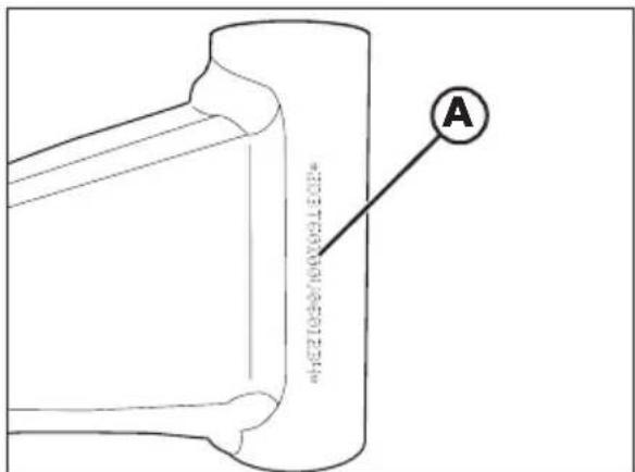
FRAME IDENTIFICATION
Frame identification data A are stamped on the right side of the steering head tube.
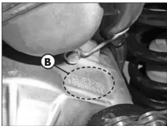
ENGINE IDENTIFICATION
Engine identification data B are stamped in the area shown in the figure.
TOOLS KIT
The following items are supplied as standard: operation, maintenance manual, tool kit and the cable adapter to connect the CAN socket to a scantool.
FAMILIARIZING WITH THE VEHICLE

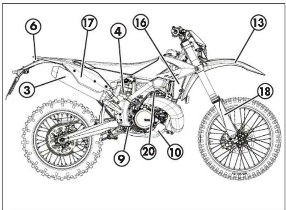
MAIN PARTS:
1 - Fuel tank
2 - Tank cap
3 - Silencer
4 - Rear shock absorber
5 - Headlight
6 - Rear light
7 - Side stand
8-Fork
9 - Rider's footrests
10 - Lower bumper
(Bumper kit)
11 - Saddle
12 - Engine
13 - Front mudguard
14 - Number-plate holder
15 - Side panel air filter
cover
16 - Front side panel
17 - Reqr side panel
18 - Fork covers
19 - Rear mudguard
20 - Kickstarter
SPECIFICATIONS
WEIGHT
Weight in running order with full fuel and optional 107 kg (front 51 Kg; rear 56 Kg)
DIMENSIONS
| maximum length (with plate holder) | 2270 mm |
| maximum width | 810 mm |
| overall height | 1255 mm |
| wheelbase | 1477 mm |
| saddle height | 910 mm |
| ground clearance | 315 mm |
| footrest height | 410 mm |
FRAME .........molybdenum steel with double cradle split above exhaust port
TYRES
| Dimensions Pressure [Bar] | |||
| Front tyre Rear tyre | Front tyre Rear tyre | ||
| 90/90-21 | 120/80-18 | 1,5 (road use) 1,8 (road use) | |
| 80/100-21 | 120/90-18 | ||
| 130/90-18 | 1 (off-road use) 1 (off-road use) | ||
front rim 21x1,6-36 holes rear rim 18x1,85-36 holes
WHEELS
| Dimensions | |
| Front Rear | |
| J 1.6x21 J 1.85x18 | |
CAPACITIES
| fuel tank | 8,5 liter |
| including reserve | 1,5 liter |
| coolant circuit | 1,3 liter |
| gear oil | 690 ml following normal maintenance work |
| 720 ml following a complete engine review |
FRONT SUSPENSION
Open cartridge hydraulic upside-down fork (Ø48 mm shafts)
spring. K 3,9 N/mm
oil type . Fuchs SAE 5W
oil quantity 510 g
wheel excursion 290 mm
compression clicks (from completely closed) 10
rebound clicks (from completely closed) 10
sping preload clicks (from completely open) 0
REAR SUSPENSION
Single shock absorber with compound lever
spring. K 4,8 Kg/mm
static sag load - SAG - (see page 46) 35 mm
shock absorber travel 135 mm
rear wheel travel 290 mm
compression clicks, high speeds (from completely closed) 23
compression clicks, low speeds (from completely closed) 26
rebound clicks (from completely closed) 33
FRONT BRAKE
260 ~mm disc and dual-piston floating caliper
REAR BRAKE
240 ~mm disc and single-piston floating caliper
ENGINE
| Version RR 125 | |
| Type | Single-cylinder, 2-stroke, liquid cooled and electric start |
| Bore x stroke [mm] | 54 x 54,5 |
| Displacement [cm3] | 124,8 |
| Compression ratio | 15:1 |
| CO2 [g/km] * # | 74 |
| Fuel consumption [l/100km] * # | 3,21 |
- Only valid for EUROPA version
WMTC cycle related data, for class L vehicles
Fuel system . carburetor
Carburetor
| Version | RR 125 Europe RR | 125 |
| Main jet 95 175 | ||
| Slow jet 35 50 | ||
| Start jet 50 85 | ||
| Needle N84I NOZH | ||
| Needle position (from top) 3° | 3° | |
| Air screw turns (from all closed) | 1+1/2 | 2+1/4 |
Cooling system . forced liquid circulation by pump
Spark plug .BR9ECMVX
Clutch. wet, multidisc
Gearchange
| Version | RR 125 Europe RR | 125 |
| Primary drive 23/73 23/73 | ||
| Gear ratio \( 1^{\text{st}} \)gear 12/33 12/33 | ||
| Gear ratio \( 2^{\text{nd}} \)gear 15/31 15/31 | ||
| Gear ratio \( 3^{\text{rd}} \)gear 17/28 17/28 | ||
| Gear ratio \( 4^{\text{th}} \)gear 19/26 19/26 | ||
| Gear ratio \( 5^{\text{th}} \)gear 21/25 21/25 | ||
| Gear ratio \( 6^{\text{th}} \)gear 20/20 20/20 | ||
| Final drive 13/45 13/50 |
Exhaust valve....centrifugal operation with reaction springs
Ignition CDI without trembler, with digital variable spark advance
Starting. Kick-starter
1
ELECTRICAL SYSTEM ELECTRICAL DIAGRAM
GENERAL INFORMATION
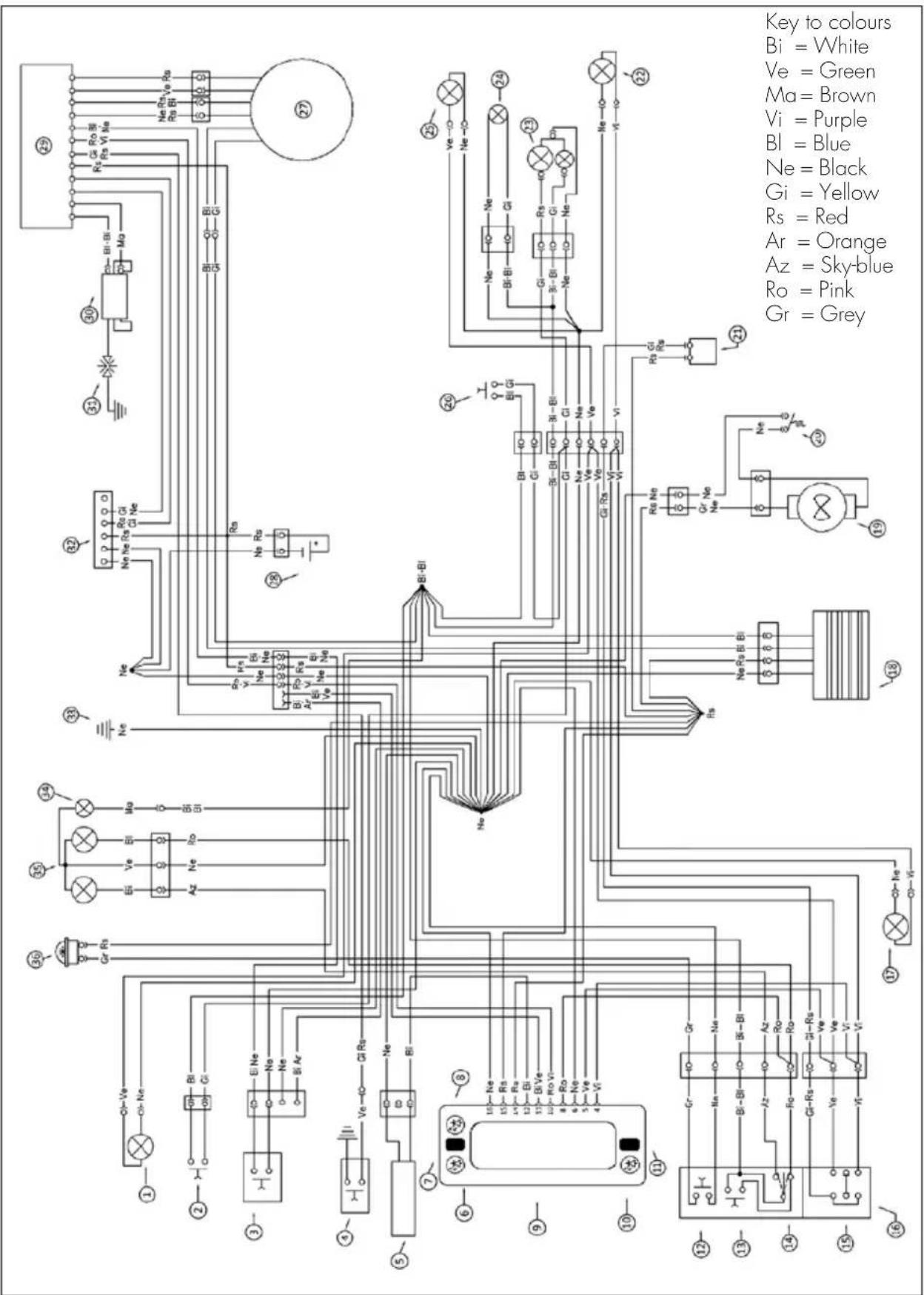
LEGEND ELECTRICAL DIAGRAM
1) RIGHTHAND FRONT TURN INDICATOR 12V 6W
2) FRONT BRAKE LIGHT BUTTON
3) ENGINE STOP BUTTON
4) SECOND MAP SWITCH (OPTIONAL)
5) WHEEL REVOLUTION SENSOR
6) TURN INDICATORS WARNING LIGHT
7) RIGHT BUTTON
8) DIAGNOSIS WARNING LIGHT
9) DASHBOARD
10) HIGH BEAM TELL TALE LAMP
11) LEFT BUTTON
12) HORN BUTTON
13) FLASH-TO-PASS BUTTON
14) HEADLIGHT SELECTOR
15) TURN SIGNAL LAMPS SWITCH
16) LEFT-HAND CONTROL GROUP
17) LEFT-HAND FRONT TURN INDICATOR 12V 6W
18) REGULATOR
19) ELECTRIC FAN (OPTIONAL)
20) THERMOSWITCH
21) UNIT TURN SIGNAL LAMPS
22) LEFT-HAND REAR TURN INDICATOR (12V 6W BULB)
23) TAIL LIGHT WITH LED
24) NUMBER-PLATE LIGHT
25) RIGHT-HAND REAR TURN INDICATOR (12V 6W BULB)
26) REAR STOP BUTTON
271 GENERATOR
28) CONDENSATOR 4700 F
29) ELECTRONIC CONTROL UNIT
30) HT COIL
31) SPARK PLUG
32) DIAGNOSIS CONNECTOR
33) FRAME EARTH
34) PARKING LIGHT 12V 5W
35) HEADLIGHT (12V-35/35W BULB)
36) 12V HORN
1
BULBS
High beam/low beam .HS1 12V-35/35W
Parking/daytime 12V-W5W
Turn indicators 12V-H6W
Rear position light/Stop light/License plate light LED
RECOMMENDED LUBRICANTS AND LIQUID
To maximize the vehicle's performance and ensure many years of trouble-free operation, we recommend using the following products:
| PRODUCT TYPE SPECIFICATIONS | |
| FUEL | GASOLINE (CE6 GASOLINE 95 RON) |
| MIXTURE OIL LIQUI MOLY RACING SYNTH 2T | |
| GEAR AND CLUTCH OIL LIQUI | MOLY RACING SYNTH 10W50 |
| BRAKE OIL LIQUI MOLY BRAKE | FLUID DOT 5.1 |
| CLUTCH ACTUATOR OIL LIQUI | MOLY BRAKE FLUID DOT 5.1 |
| FORK OIL FUCHS SAE 5W | |
| TIE ROD GREASE LIQUI MOLY SCHMIERFIX | |
| LIQUID COOLANT | LIQUI MOLY COOLANT READY MIX RAF12 PLUS |
Note:
It is essential that all renewals should be performed with the products listed in the table above.
CHAPTER 2 OPERATION
CONTENTS
Main parts 18
Fuel tank cap 18
Fuel cock 18
Starter. 19
Clutch lever 19
LH switch 20
RH switch 20
Front brake lever and gas control 20
Gear change lever. 21
Brake pedal 21
Kickstart 21
Side stand 21
Keys 22
Steering lock. 22
Digital rpm indicator operating instructions. 23
Checks before and after use 33
Running in 33
Refuelling 34
Starting the engine 35
Engine shut-down 35
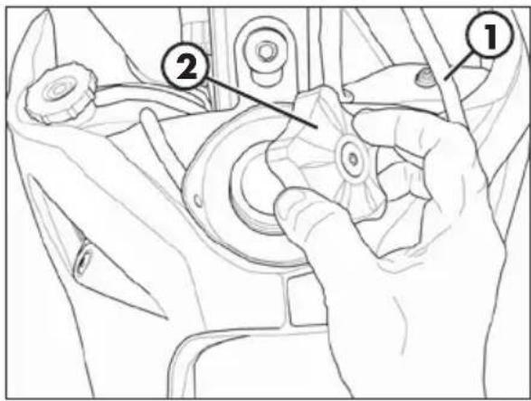
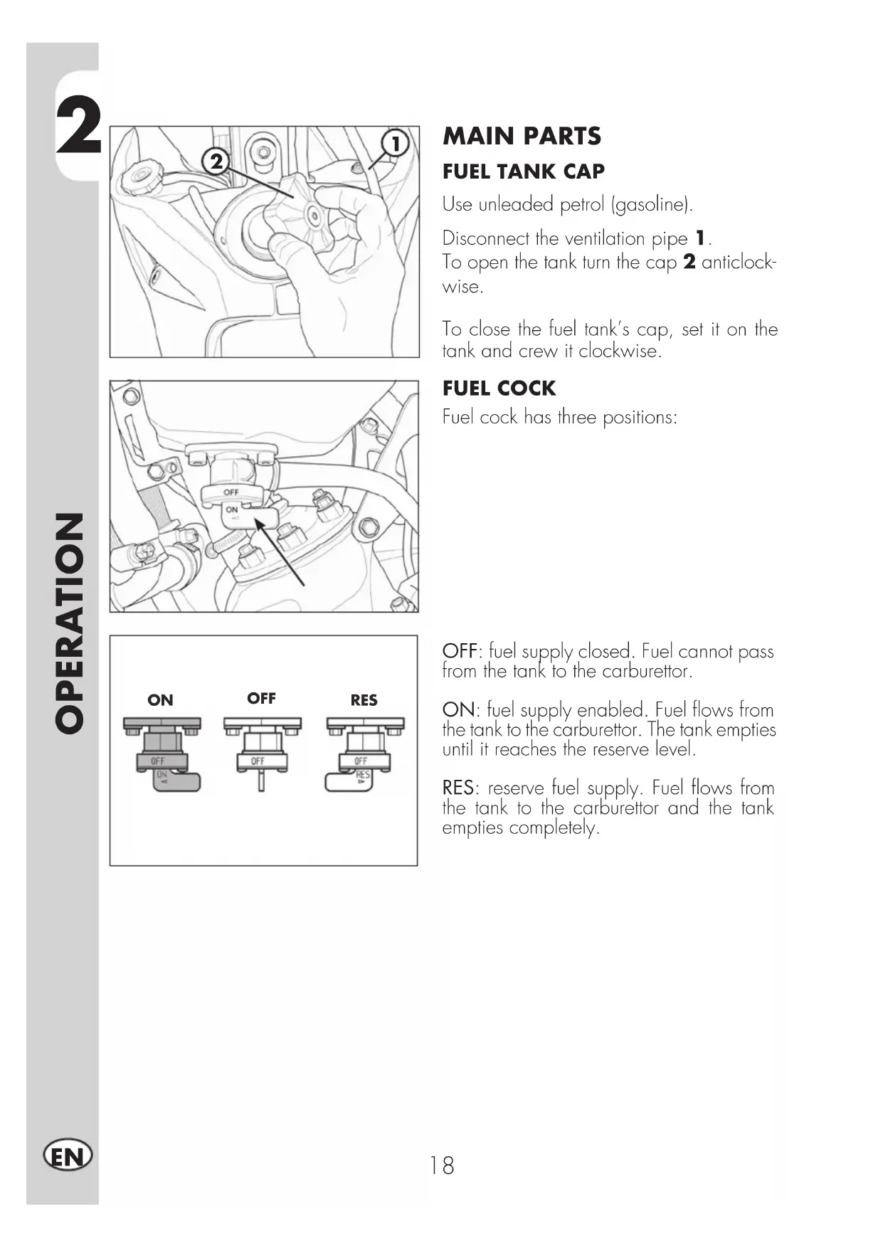
MAIN PARTS FUEL TANK CAP
Use unleaded petrol (gasoline).
Disconnect the ventilation pipe 1.
To open the tank turn the cap 2 anticlockwise.
To close the fuel tank's cap, set it on the tank and crew it clockwise.
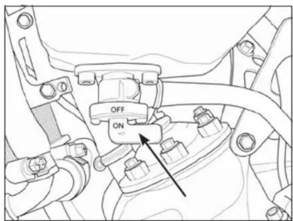
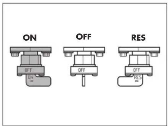
FUEL COCK
Fuel cock has three positions:
OFF: fuel supply closed. Fuel cannot pass from the tank to the carburettor.
ON: fuel supply enabled. Fuel flows from the tank to the carburettor. The tank empties until it reaches the reserve level.
RES: reserve fuel supply. Fuel flows from the tank to the carburettor and the tank empties completely.
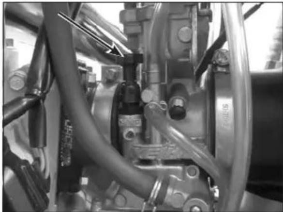
STARTER
The starter lever is located on the carburettor.
To operate the choke pull it upward.
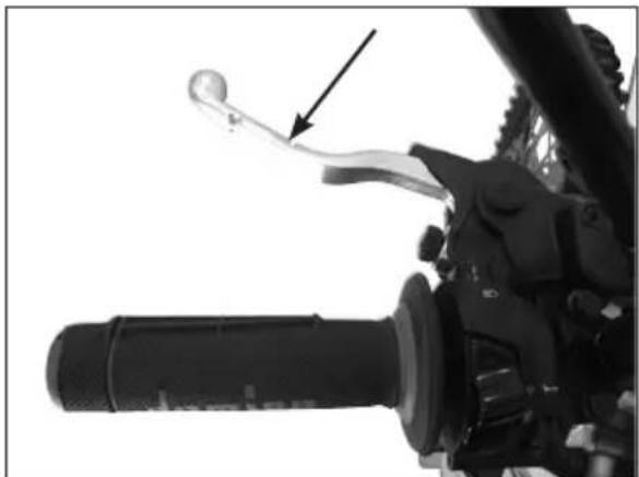
CLUTCH LEVER
Clutch lever is fitted to the left-hand side of the handlebars.
2
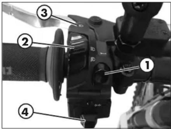
LH SWITCH
The dip and service switch is located on the left side of the handlebar and is composed as follows:
1 - Horn button;
2 - Dip switch:
peking lights and high beam;
parking lights and low beam;
3 - Flash-to-pass button;
4 -Turn signal light switch: shifting lever left or right activates the left or right indicators. When released, the lever returns to the central position. Press it to turn the indicators off.
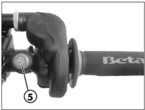
RH SWITCH
The button 5 turns off the engine.
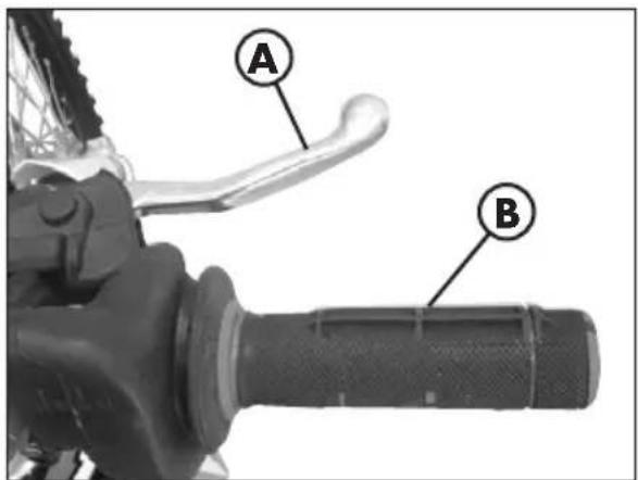
The front brake lever A and the gas throttle B are located on the right side of the handlebar.
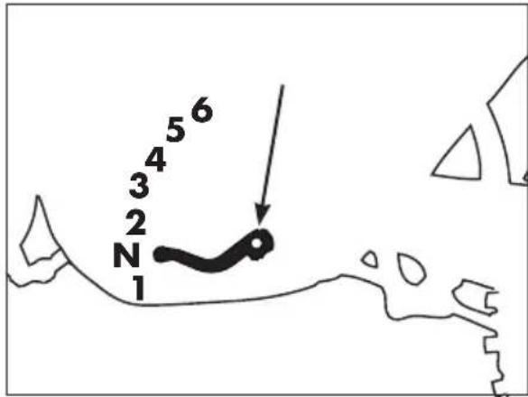
GEAR CHANGE LEVER
Gear change lever is fitted to the left side of the engine.
The positions corresponding to the different gears are shown in the figure.
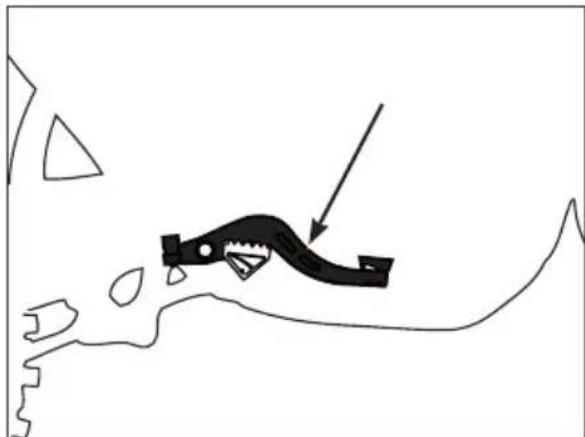
BRAKE PEDAL
Brake pedal is located in front of the right-hand footrest.
The rear brake is operated by pressing down the pedal.
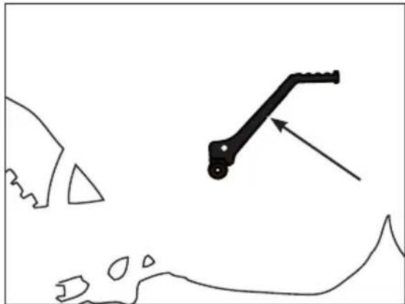
KICKSTART
Kickstart is fitted to the right-hand side of the engine.
The upper part of the kickstart can be oriented.
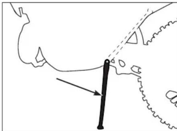
SIDE STAND
Press down side stand with the foot and lean the vehicle against it.
Ensure that the ground is solid and the vehicle stands steadily.
2
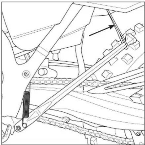
If the vehicle is used off-road, the closed stand can be further fastened by means of rubber band.
KEYS
The vehicle is supplied with two keys (one key and its spare).
STEERING LOCK
To activate the steering lock:
-
turn the handlebar counterclockwise;
-
push the key and turn counterclockwise; Remove the key from this position.
To deactivate the steering lock:
-
turn the key clockwise;
-
turn the handlebar clockwise;
From this position, the handlebar is free to move, the key can be removed.
WARNING: do not keep the spare key inside the vehicle, but in a safe place.
We suggest you note the code number stamped on the keys. In this way you can obtain a duplicate.
DIGITAL RPM INDICATOR OPERATING INSTRUCTIONS
Index
1 General information
2 Operating condition
3 General characteristics
3.1 Dashboard start-up process
3.1.1 Wake up events
3.2 LCD Display
3.2.1 LCD general characteristics
3.2.2 Speed
3.2.3 Odometer
3.2.4 Trip A
3.2.5 Trip B
3.2.6 Clock
3.2.7 Ride Time
3.2.8 Unit option display
3.2.9 Wheel length display
3.2.10 Motorbike battery level
3.2.11 Push Button Management Table
3.3 Telltales
4 Coin battery
1 GENERAL INFORMATION
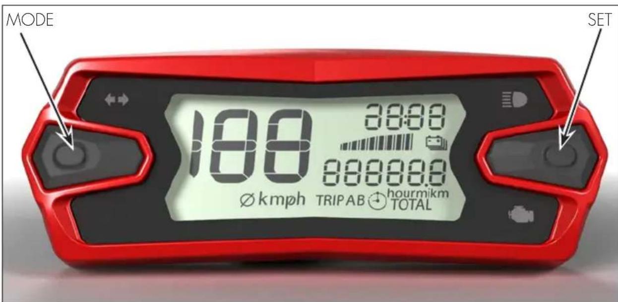
The dashboard integrates these main blocks:
- LCD display for showing all required information
-2 pushbuttons - Coin battery

Standard supply voltage: 10 to 16V
Minimum supply voltage w/o reset: 6.5V
3 GENERAL CHARACTERISTICS
3.1 DASHBOARD START-UP PROCESS
The dashboard do some start-up process when it is turned ON. There are three different wakes up events for starting the dashboard.
This startup process consists in turning ON the telltales and the LCD backlight and the LCD will show all the segments during 2 seconds.
After the start-up process, dashboard is kept ON during 30 seconds if there are no events as pushbutton press, speed signal or engine ON.
3.1.1 WAKE UP EVENTS
3.1.1.1 Motorbike power supply is activated
When the power supply of dashboard is activated (e.g. when engine is turned on), the dashboard does the normal startup process and is kept ON while
3.1.1.2 Wheel revolution
If the motorbike generated a speed pulse, the dashboard will be turned ON doing the normal startup process. After the start-up process the dashboard will display the normal mode, and will be ON during 30 seconds if no speed pulse is generated.
3.1.1.3 Button is pushed
If one or both buttons are pushed the dashboard will be turned ON doing the start-up process.
After the start-up process the dashboard will display the normal mode, and will be ON during 30 seconds if no pushbutton is pressed.
3.2 LCD DISPLAY
Dashboard is equipped with a LCD display for showing following information:
- Speed
- State of the power supply system
- Odometer (distance or ride time)
- Trip TOTAL-A-B (distance or ride time)
- Clock
Each information/data is refreshed independently at different rate, depending on information type and variability of this information.
3.2.1 LCD GENERAL CHARACTERISTICS
Each information/data is refreshed independently at different rates, depending on information type and variability of this information.
3.2.2 SPEED
- Dashboard computes and displays the motorbike speed on LCD display. Speed information can be obtained from:
Dedicated digital input for measuring speed sensor frequency.
3.2.2.1 Speed digital input configuration
Configuration parameters for speed input and speed visualization.
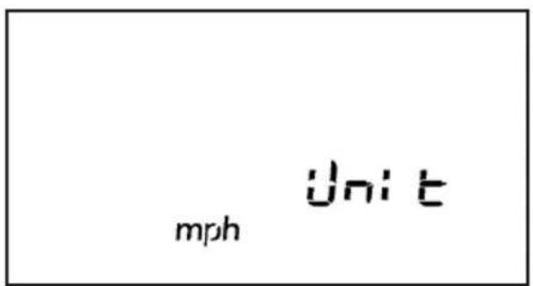
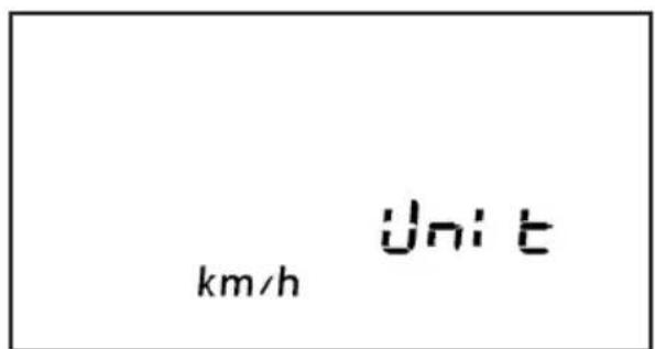
Dimensions displayed: [km/h or mph]
Minimum speed indication: [5km / h]
Speedometer advance: [5 %]
Wheel parameters:
-
Wheel perimeter selectable between 2 values:
-
Default wheel perimeter value: (enduro) 2100mm
- 2nd wheel perimeter value: 1811mm
Pulses per turn: [1 pulses/turn]
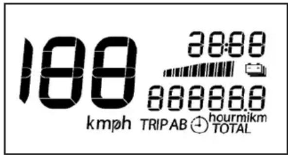
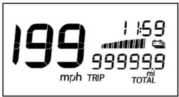
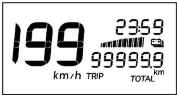
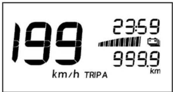
3.2.2.2 Speed LCD
Speed and speed units are permanently displayed (km/h or mph).
km/h display range: 0 to 199km / h
mph display range: 0 to 199mph.
Leading zeros suppressed.
Following picture shows LCD displaying speed in km/h and mph:

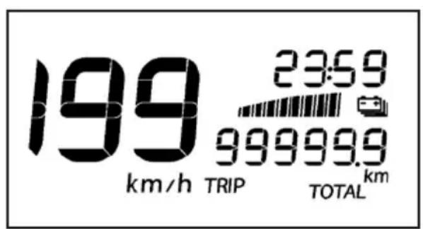
3.2.3 ODOMETER
Dashboard provides an odometer and is displayed on LCD display.
This option can be displayed scrolling by "MODE" button.
6 digits and "ODO" icon lighted.
Leading zeros not suppressed.
Display range from 000000 to 999999 km or miles. If odometer is greater than 999999 km, odometer will be fixed as 999999km.
Minimum display unit: 1 km or mile.
3.2.4 TRIP A
Dashboard provides 2 trips and is displayed on LCD display.
This option can be displayed scrolling by "MODE" dashboard button.
4 digits (3digits + decimal point + 1 digit), "TRIP" icon lighted and "A" on the left. Leading zeros suppressed.
Display range from 0.0 to 999.9km or miles.
Trip A counter counts from 0 up to 999.9 and then rolls over to 0 and continue counting.
Minimum display unit: 0.1 km or miles.
Trip A reset by pressing "SET" button more than 2 seconds.
Trip A display the Trip A ride time pressing "SET" button less than 2 seconds. Ride time is showed as an hour decimal number. Examples: 30 min is 0.5 or 1h20min is 1.3.
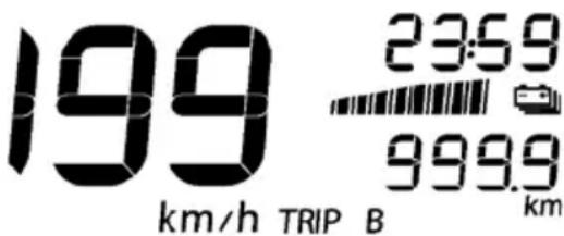
3.2.5 TRIP B
This option can be displayed scrolling by "MODE" dashboard button.
4 digits (3digits + decimal point + 1 digit), "TRIP" icon lighted and "B" on the left.
Leading zeros suppressed.
Display range from 0.0 to 999.9km or miles.
Trip B counter counts from 0 up to 999.9 and then rolls over to 0 and continue counting.
Minimum display unit: 0.1 km or miles.
Trip B reset by pressing "SET" button more than 2 seconds.
Trip B display the Trip B ride time pressing "SET" button less than 2 seconds. Ride time is showed as an hour decimal number. Examples: 30 min is 0.5 or 1h20min is 1.3 .
3.2.6 CLOCK
Dashboard provides a clock and is displayed on LCD display. Time is obtained from internal crystal quartz and is kept while dashboard is connected to coin battery.
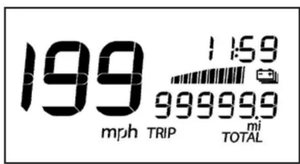
| Clock format If units of m | measure are km 24h |
| If units of measure are mi 12h |
3.2.7 RIDE TIME
Dashboard provides a Ride Time and is displayed on LCD display. Time is obtained from internal crystal quartz and is kept with a push buttons. When the motorbike is turned on the ride time starts again.

3.2.8 UNIT OPTION DISPLAY
Dashboard provides the possibility to change the units and be displayed.
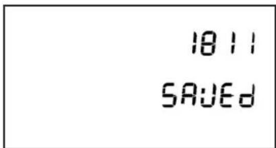
3.2.9 WHEEL LENGTH DISPLAY
- Dashboard provides the possibility to change the wheel length and be displayed.
- The length can be selected between 2 fixed values:
2100mm (enduro) 1811mm
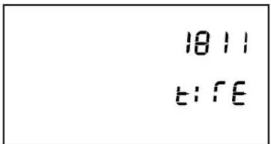
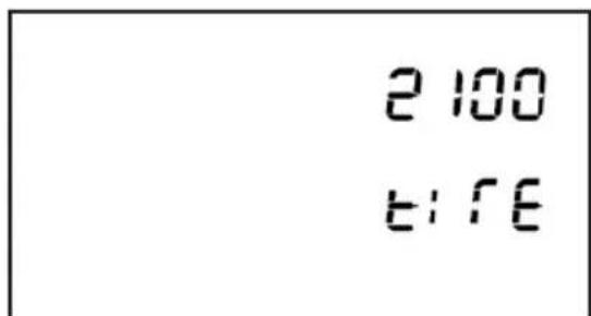
Pushing mode and set more than 2 seconds wheel length is saved. "Saved" will be displayed during 1 second on Dashboard.
3.2.POwer SUPPLY SYSTEM LEVEL
Dashboard displays level of voltage of the power supply:
Relationship between bars and level of voltage:
| Bars Voltage [V] Bars Voltage [V] | |||
| 0 → 1 | 11 | 4 → 5 | 13 |
| 1 → 2 | 11.5 | 5 → 6 | 13.5 |
| 2 → 3 | 12 | 6 → 7 | 14 |
| 3 → 4 | 12.5 | 7 → 8 | 14.5 |
The level is updated every 30 seconds. Each update increase or decrease 1 bar.

WARNING:
If the word "HIGH" appears with the indicator flashing, turn off the engine and contact authorised BETAMOTOR customer service.
199
km/h
2359
H16H
3.2.11 PUSH BUTTON MANAGEMENT TABLE
| Mode Speed Function Button Time (sec) Activity | |||||
| ODO MODE | <2 TOTAL- TRIPA - | TRIPB - TOTAL | |||
| SET <2 Ride | time- km - | Ride time | |||
| O CLOCK MODE MODE&SET >2 CLOCK MODE | |||||
| O WHEEL LENGTH MODE | DE >10 WHEEL LENGTH MODE | ||||
| O | SET >10 Km/h - mph - | Km/h | |||
| TRIPA | MODE <2 TRIPA - TRIPB - ODO - TRIPA | ||||
| SET <2 Ride | Time- Km- | Ride time | |||
| SET >2 Reset | Trip A and | Ride time | |||
| O CLOCK MODE MODE&SET >2 CLOCK MODE | |||||
| TRIPB | MODE <2 TRIPB - ODO - TRIPA - TRIPB | ||||
| SET <2 Ride | Time- Km- | Ride time | |||
| SET >2 Reset | Trip A and | Ride time | |||
| O CLOCK MODE MODE&SET >2 CLOCK MODE | |||||
| Mode Speed | Function | Button Time (sec) | Activity | ||
| CLOCK MODE | 0 | "On Entering Stop Clock Mode" | MODE <2 Increase in the Hour digits | ||
| MODE >2 | Speedy increase in the Hour digits | ||||
| SET <2 Increase in the minutes digits | |||||
| SET >2 | Speedy increase in the minutes digits | ||||
| MODE&SET >2 Exit clock set mode and save the value | |||||
| NO ACTION | >10 Auto exit without saving | ||||
| Mode Speed | Function | Button Time (sec) | Activity | ||
| WHEEL LENGTH | 0 | On entering wheel length mode | MODE | <2 | Change wheel 2100 - 1811 |
| MODE&SET | >2 | Exit wheel length mode and save the value | |||
| NO ACTION | >10 | Auto exit without saving |
3.3 TELLTALES
LED number indicator:
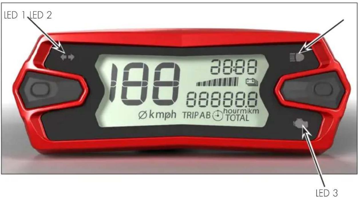
Telltales/Indicator lights specifications:
Number of telltales: 3
| LED number | Function Symbol | |
| LED 1 Blinkers | ↔→ | |
| LED 2 High beam | ≡D | |
| LED 3 | MIL telltale (Engine management system fault) |
Power + 12V are provided to the dashboard only when the bike is turned on (regulator line).
Blinkers LED
The system activates the indicator in synchrony with the activation of the direction indicators
High beam LED
The system activates the indicator in synchrony with the activation of the high beam.
MIL LED
Indicates a fault in the engine management system. In case of prolonged lighting, consult an authorised Betamotor dealer as soon as possible.
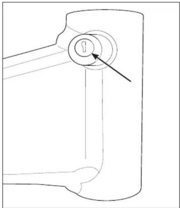
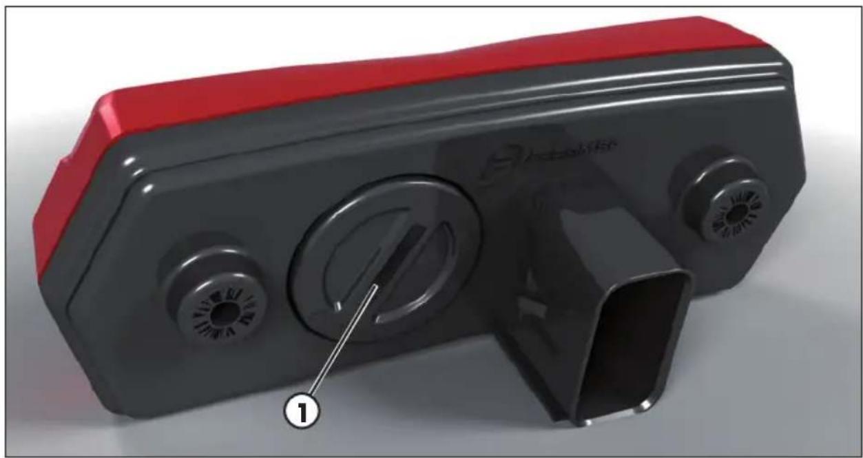
4 COIN BATTERY
** Dashboard is equipped with a coin battery (1) for keeping time when motorbike is off.** Coin size: CR2032.
CHECKS BEFORE AND AFTER USE
For safe driving and long vehicle life you should:
1 Check all fluid levels.
2 Check the correct operation of the brakes and brake pad wear (page 60).
3 Check pressure, general condition and thickness of tread (page 68).
4 Check that the spokes are properly tightened.
5 Check the tensioning of the chain (page 69).
6 Check the adjustment and the operation of all the cable controls.
7 Inspect all the nuts and bolts.
8 With the engine running, check the operation of the headlight, the rear and brake lights, the indicators, the warning lights and the horn.
9 Wash the motorcycle thoroughly after off-road use (page 72).
RUNNING IN
The running-in period lasts approximately 5 hours, during which it is advisable to:
1 Make the first refuelling with a mixture of 3% .
2 Use the oil indicated on page 16 in the "Recommended lubricants and liquids" table.
3 During the first 3 hours of operation the engine should only be used to approximately 70 percent of its power. In addition, the engine speed should not exceed 11,000 rpm.
4 For the next 2 hours of operation the engine should only be used to about 90 percent of its power.
5 Use the vehicle after properly warming up the engine.
6 Avoid travelling at constant speed (changing the speed causes the different components to bed in evenly and more quickly).
This procedure should be followed each time piston, piston rings, cylinder, crankshaft or crankshaft bearings are replaced.
WARNING
Replace the transmission oil after the first 3 hours or after 15 l. of mixture.
REFUELLING
See page 16 for the fuel specifications. Mix fuel with oil according to the percentages shown in the table. Use the oil indicated on page 16 in the "Recommended lubricants and liquids" table.
| RR 125 Europa RR 1 | 25 |
| 2% 2,5% |
Fuel tank capacity is shown on page 10.
To refuel open the tank cap (page 18).
After refuelling, screw the cap back and tighten securely.
WARNING
The refuelling should be performed with the engine off.

WARNING:
Fire hazard. Fuel is highly flammable.

Always stop the engine when refuelling and keep open flames and lighted cigarettes away.

Do not top up fuel while using a mobile phone.
Refuel in an open well ventilated area.
Pay special attention so that the fuel does not come into contact with hot parts of the vehicle. Immediately clean up any spilled fuel.

WARNING: Risk of poisoning.
Fuel is poisonous liquid and a health hazard.

Fuel must not come into contact with the skin, eyes, and clothing. Do not breathe in the fuel vapours. If contact occurs with the eyes, rinse immediately with plenty of water and seek medical advice. If contact occurs with skin, immediately clean contaminated areas with soap and water. If fuel is swallowed, contact a doctor immediately. Change clothing that is contaminated with fuel.
WARNING: Environmental pollution hazard.
The fuel must not contaminate the ground water, the ground, or the sewage system.
STARTING THE ENGINE
Move the fuel tank valve in ON or RES position (page 18).
Check that the gears are in neutral (page 21).
Pull the clutch lever (page 19).
Close the side stand (page 21).
WITH KICK-STARTER (page 21): (page 21):
Depress the kick-starter with a sharp movement of the foot.


ATTENTION
Once the pedal has been depressed, release it immediately. This avoids jolts to the entire ignition group and to the foot.
COLD STARTING:
Operate the starter (page 19), start the vehicle as described above, wait a few seconds, then move the starter back to its starting position.
ENGINE SHUT-DOWN
To shutdown the engine press the button on the left switch unit (page 20).
NOTE:
With the engine off, make sure the fuel cock is set to OFF (page 18).
CHAPTER 3 ADJUSTMENTS
CONTENTS
Key to symbols. 38
Brakes 38
Front brake 38
Rear brake 38
Clutch 38
Adjustment of gas clearance. 39
Adjusting the idle speed 39
Carburetor settings according to the working conditions. 40
Exhaust valve control adjustment 42
Handlebar adjustment 42
U-bolt position adjustment. 42
Adjustment of the handlebar position 43
Adjusting fork 43
Adjusting the rebound damper 43
Adjusting the spring preload 44
Shock absorber 44
Adjusting the rebound damper 44
Adjusting the compression damper 44
Adjusting the hydraulic compression damper (high and low speeds) .... 45
Adjusting the spring preload 45
Suspensions settings according to the weight of the rider. 46
Static sag load test 46
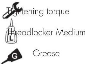
KEY TO SYMBOLS
BRAKES
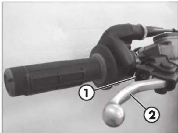
FRONT BRAKE
The front brake is disk type with hydraulic control.
The home position of brake lever 2 can be adjusted by means of screw 1.
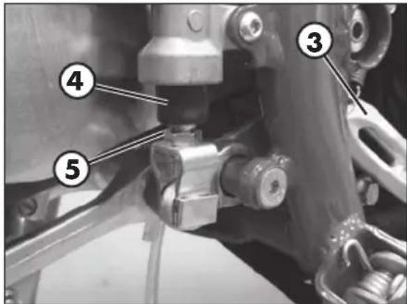
REAR BRAKE
The home position of brake pedal 3 can be altered by turning adjusting screw 5 after loosening the counternut located under dust cap 4. Loosen the counternut and turn the adjusting screw until the desired height is obtained. Retighten the counternut after completing the operation.
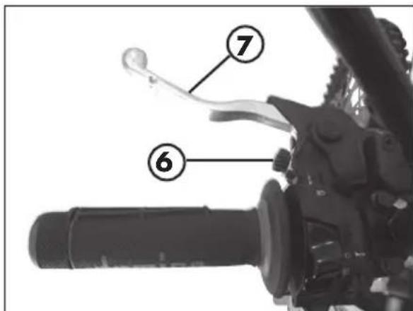
CLUTCH
The adjustment screw 6 allows adjustment of the distance of lever 7 from the knob. The empty run is recovered automatically.
ADJUSTMENT OF GAS CLEARANCE
The throttle control cable should always have a 3 - 5mm play. In addition, the idle speed should not change when the handlebars are fully rotated to the left or right. Push back protective cap 1. Loosen counternut 2 and turn adjusting screw 3. Tighten the counternut and check that the throttle twist grip turns smoothly.
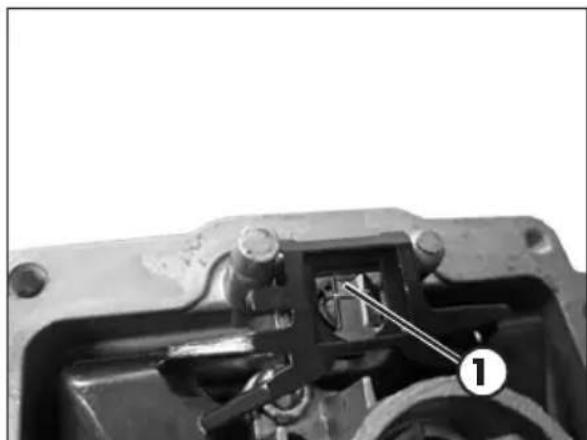
ADJUSTING THE IDLE SPEED
lding adjustment greatly affects the appropriate start-up and the accelerator response.
ldling is adjusted through adjustment screw 1 and air adjustment screw 2. Adjustment screw 1 adjusts the basis position of the gas valve. Turn the screw clockwise to increase the rotation conditions and counterclockwise to diminish it. The air adjustment screw 2 adjusts the quantity of which is mixed to the fuel for idling. If the screw is turned counterclockwise, the quantity of air increases (thin mix), if turned clockwise, the quantity of air diminishes (fat mix).
To properly adjust the idle speed, follow these steps:
- Tighten the air adjustment screw no. 2 fully and then loosen it up to the value described in the carburetor setting table (page 12)
- Warm the engine for approx. 5 minutes, until the operational temperature is attained.
- Slowly turn the air adjustment screw 2 clockwise, until idling starts diminishing.
- Mark the position, then slowly turn the air adjustment screw no. 2 counterclockwise, until idling decreases again.
- Adjust the screw between these two positions, at the highest idling point..
If a remarkable increase in the rpm occurred during the adjustment above, idling is to be reduced and taken back to the normal level, and then execute the above procedure.
If no satisfactory results are obtained after the procedure, this may be due to an incorrect slow-running jet.
If the air adjustment screw has been thoroughly tightened, but the rpm have not varied, a lower size slow-running jet is to be used.
Execute the adjustment procedure again after replacing the jet.
NOTE:
The correct idling should be between 1700 and 1800 rpm.
CARBURETOR SETTINGS ACCORDING TO THE WORKING CONDITIONS
See the following tables to adjust the carburetor settings according to ambient temperature and altitude.
Legend:
| SLM Above sea level |
| AVA Air screw opening (from all closed) |
| Gm Slow jet |
| SPL Needle |
| POS Needle position (from top) |
| GM Main jet |
| VLV Valve |
Standard settings
| Version RR 125 | |||||||
| Altitude(SLM) | Carburetor setting | Ambient temperature | |||||
| -20°C÷÷7°C | -6°C÷5°C | 6°C÷15°C | 16°C÷24°C | 25°C÷36°C | 37°C÷49°C | ||
| -2°F÷20°F | 19°F÷41°F | 42°F÷60°F | 61°F÷78°F | 79°F÷98°F | 99°F÷120°F | ||
| 3000 m | AVA 2,25 2,7 | 5 2,75 3, | 25 3,25 | ||||
| 10000 ft | Gm 50 48 48 | 48 48 48 | |||||
| ↑ | GM 175 | 172 170 | 168 165 | ||||
| SPL NOZH | NOZH NOZH | NOZH NOZH | NOZH NOZH | NOZH NOZH | NOZH NOZH | ||
| 2301 m | POS 3 3 2 2 | 2 | |||||
| 7501 ft | VLV | 7 7 7 7 | 7,5 | ||||
| 2300 m | AVA 2,25 2,25 | 25 2,75 2, | 75 3,25 3, | 25 | |||
| 7500 ft | Gm 50 | 50 50 50 | 50 50 | ||||
| ↑ | GM 178 | 175 172 | 170 168 | 165 | |||
| SPL NOZH | NOZH NOZH | NOZH NOZH | NOZH NOZH | NOZH NOZH | NOZH NOZH | ||
| 1501 m | POS 3 3 3 2 | 2 2 | |||||
| 5001 ft | VLV | 7 7 7 7 7 | 7,5 | ||||
| 1500 m | AVA 2,25 2,25 | 25 2,25 2, | 75 2,75 3, | 25 | |||
| 5000 ft | Gm 52 | 50 50 50 | 50 50 | ||||
| ↑ | GM 180 | 178 175 | 172 170 | 168 | |||
| SPL | NOZG | NOZH | NOZH NOZH | NOZH NOZH | NOZH NOZH | ||
| 751 m | POS 4 3 | 3 3 2 2 | |||||
| 2501 ft | VLV | 7 7 7 7 7 | 7 | ||||
| 750 m | AVA 2,25 | 25 2,25 2, | 25 2,25 2, | 75 2,75 | |||
| 2500 ft | Gm 52 | 52 50 50 | 50 50 | ||||
| ↑ | GM 182 | 180 178 | 175 | 172 | 170 | ||
| SPL | NOZG | NOZG | NOZH | NOZH NOZH | NOZH NOZH | ||
| 301 m | POS 4 4 | 3 3 3 2 | |||||
| 1001 ft | VLV | 7 7 7 7 7 | 7 | ||||
| 300 m | AVA 1,75 | 2,25 2, | 25 2,25 2, | 25 2,75 | |||
| 1000 ft | Gm 55 | 52 52 50 | 50 50 | ||||
| ↑ | GM 185 | 182 180 | 178 175 | 172 | |||
| SPL | NOZF | NOZG | NOZG | NOZH | NOZH | NOZH | |
| 0 m | POS 5 4 | 4 3 3 3 | |||||
| 0 ft | VLV 7 7 | 7 7 7 7 | |||||
3
EXHAUST VALVE CONTROL ADJUSTMENT
ATTENTION! The vehicle is provided with an exhaust valve whose fine tuning is performed during the final try-out of the engine. The position of adjustment valve I must not be modified for any reason.
For any adjusting, please contact Betamotor's Authorized Service Network.
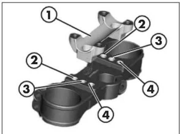
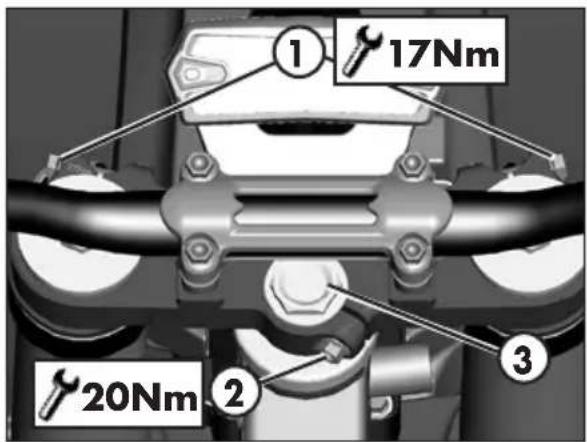
HANDLEBAR ADJUSTMENT U-BOLT POSITION ADJUSTMENT
The lower bracket 1 can be mounted in correspondence of the holes nr. 2, 3 or 4 respectively.
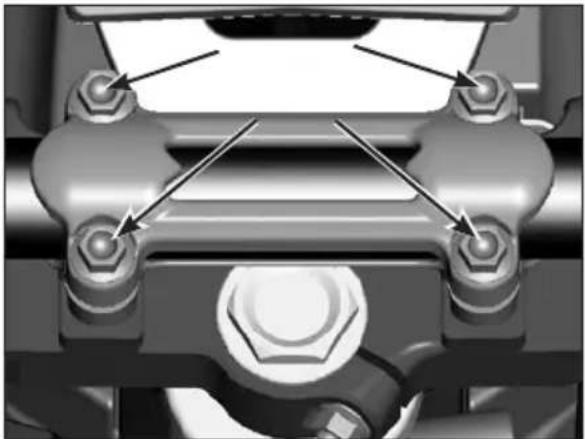
To adjust the position of the u-bolt remove the screws shown in the figure.
Remove the handlebar.
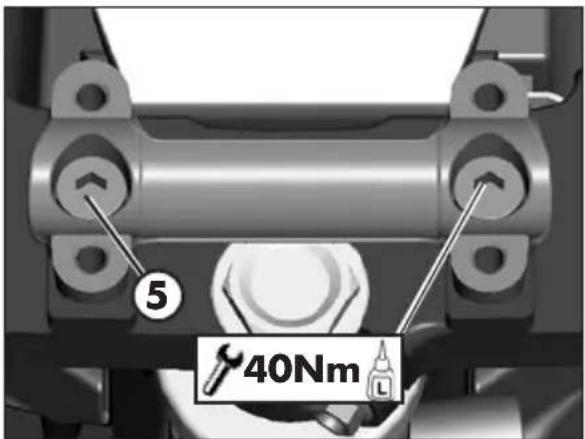
Remove the screws 5.
Position the U-bolt according to requirements.
At the end refit the screws 5 after the application of thread lock fluid and tighten to the torque indicated.
Apply the handlebar.
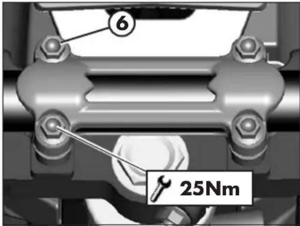
Apply the top u-bolt.
Refit the screws 6. Tighten to the torque indicated.
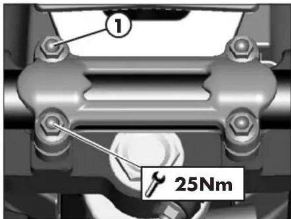
ADJUSTMENT OF THE HANDLEBAR POSITION
The handlebar can be adjusted by rotating it back and forth.
To adjust the handlebar loosen screws 1.
Position the handlebar according to requirements.
Tighten to the torque indicated.
ADJUSTING FORK
The hydraulic rebound damper determines the behaviour of the telescopic fork during extension and can be adjusted by means of knob A. Turning the screw clockwise (towards +) increases the action of the rebound damper; turning it anticlockwise (towards -) decreases the action of the rebound damper.
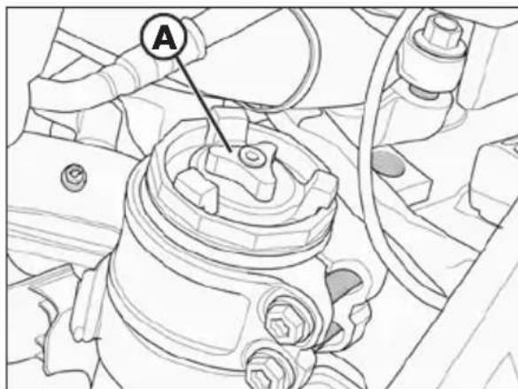
For standard calibration, refer to page 11.
3
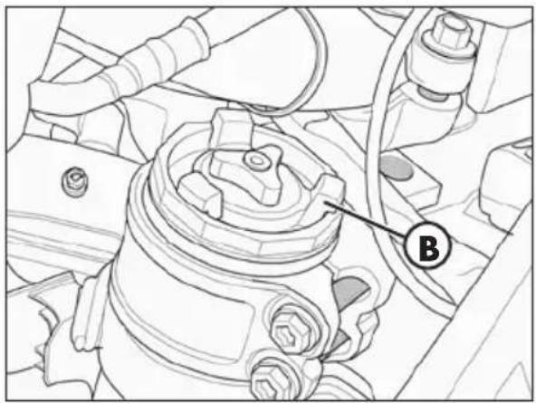
ADJUSTING THE SPRING PRELOAD
The spring preload is adjusted by using the ring nut B. Rotate clockwise to increase the spring preload or anticlockwise to decrease it.
The spring preload varies by one millimeter, each complete revolution.
For standard calibration, refer to page 11.
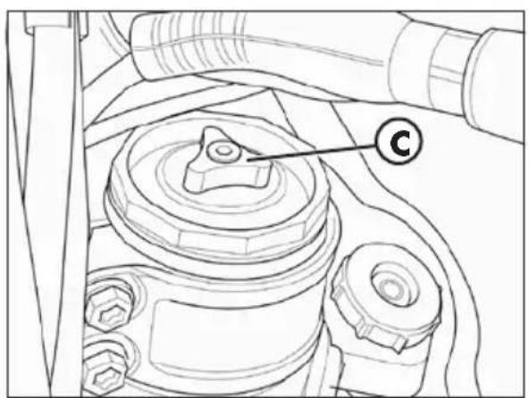
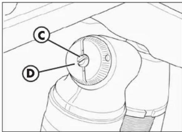
The hydraulic compression damper determines the behaviour of the telescopic fork during compression and can be adjusted by means of knob C located at the lower end of the fork legs. Turning the screw clockwise (towards +) increases the action of the compression damper; turning it anticlockwise (towards -) decreases the action of the compression damper.
For standard calibration, refer to page 11.
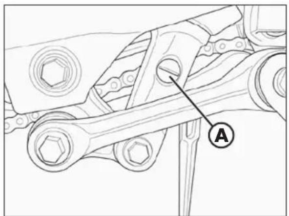
Turn screw A to adjust the hydraulic rebound damper.
Turning the screw anticlockwise (out) decreases the damping effect.
For standard setting, refer to page 11.
ADJUSTING THE HYDRAULIC COMPRESSION DAMPER (HIGH AND LOW SPEEDS)
Adjustment for low compression speed:
- Using a screwdriver, loosen screw C by turning it clockwise to increase the hydraulic compression damper.
For standard setting, refer to page 11.
Adjustment for high compression speed:
- Turn knob D anticlockwise to decrease the hydraulic compression damper.
For standard setting, refer to page 11.
WARNING:
Starting from the standard position, turn the knob anticlockwise (with a closing action), the center screw will have an integral movement, then will rotate with the knob.
For standard setting, refer to page 11.
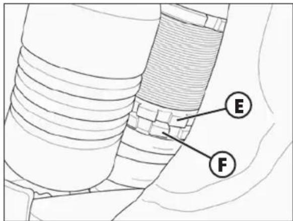
ADJUSTING THE SPRING PRELOAD
Loosen countering E, rotate ring F clockwise to increase the spring preload (and consequently the shock absorber preload) or anticlockwise to decrease it. After obtaining the desired preload, turn countering E until it stops against adjusting ring F.
For standard setting, refer to page 11.
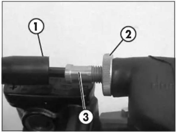
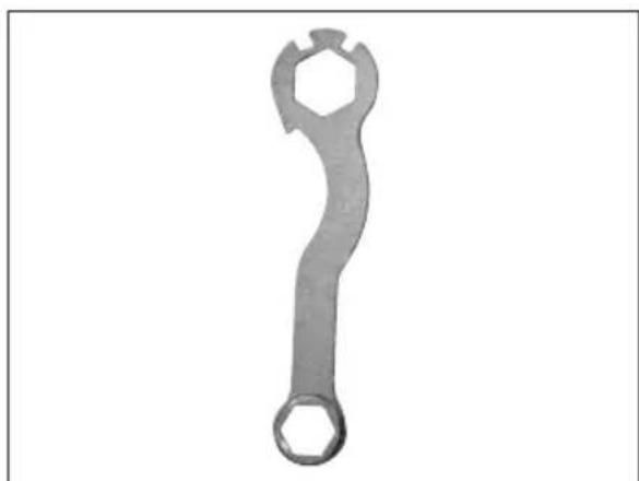
NOTE: for the handling of ring nuts use the specific wrench provided in the standard tool kit shown in the figure.
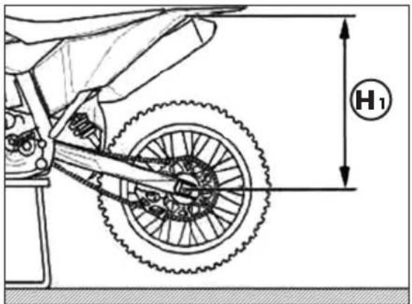
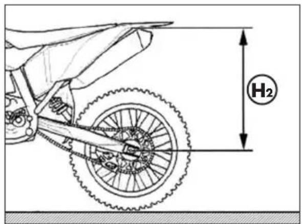
STATIC SAG LOAD TEST
To verify the static sag of the shock absorber proceed as follows:
- Place the motorcycle on the work stand.
- Measure the vertical distance between the rear wheel axle and a reference point on the rear fairings.
- Write down the dimension H_1 .
- Remove the work stand.
- Keep the motorcycle in vertical position and measure again the distance between the wheel axle and the reference point previously established.
- Write down the dimension H_2 .
Verify that the value of the static compression X = H_1 - H_2 matches the one shown on page 11. Otherwise, perform the adjustment of the spring preload as described above.
SUSPENSIONS SETTINGS ACCORDING TO THE WEIGHT OF THE RIDER
The table below shows the spring constant K of the suspensions (fork and shock absorber) depending on the weight of the driver.
Refer to the accessories catalogue Betamotor to obtain the spring codes.
| Fork | |
| Rider weight [kg] K (Spring constant) | |
| 70 - 85 3,9 | |
| 85 - 95 4,2 | |
| 95 - 105 4,6 | |
| >105 4,8 | |
| Shock absorber | |
| Rider weight [kg] K (Spring constant) | |
| 70 - 85 4,8 | |
| 85 - 95 5,0 | |
| 95 - 105 5,2 | |
| >105 5,4 | |
Standard settings
CHAPTER 4 CHECKS AND MAINTENANCE
CONTENTS
Key to symbols. 48
Engine oil 48
Check the level. 48
Replacement 50
Liquid coolant 51
Check the level. 51
Replacement 52
Air filter 54
Removing and installing air filter. 54
Air filter cleaning - RR 125 EuropE. 55
Air filter cleaning - RR 125. 55
Spark plug 55
Carburettor 56
Draining the carburettor float chamber 56
Checking the float level 57
Front brake 58
Check the level of the front brake fluid 58
Restoring the level of the front brake fluid 58
Bleeding the front brake 59
Front brake lining control 60
Brake disc thickness control 60
Rear brake 61
Check the level of the rear brake fluid 61
Restoring the level of the rear brake fluid 61
Bleeding the rear brake 62
Rear brake lining control 63
Brake disc thickness control 63
Clutch control 64
Check the level 64
Bleeding 65
Check and adjusting of steering play 66
Fork 67
Front wheel 67
Tightening 67
Tyres. 68
Rear suspension leverage 68
Chain 69
Check and adjust tightening chain 69
Check for chain wear. 70
Headlight 71
Replacing the headlight bulbs 71
Tail light 71
Cleaning the vehicle 72
General precautions 72
Prolonged inactivity 73
Scheduled maintenance vehicle 74
Tightening torque overview 76
KEY TO SYMBOLS
ENGINE OIL
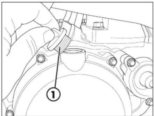
CHECK THE LEVEL
Hold the vehicle upright. Position the drive on a flat base ensuring stability.
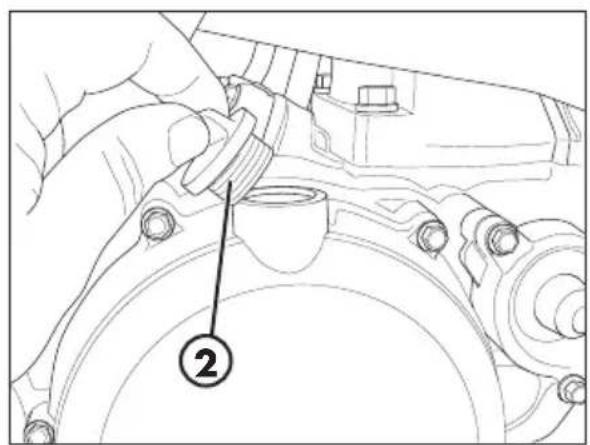
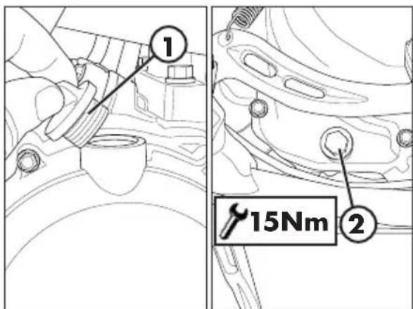
Remove the inspection cap 1.
The oil level must arrive to the lower edge of check hole.
Otherwise restore the oil level through plug 2.
The inspection cap is ONLY to check the oil level. For the oil drain, refer to the paragarfo Replacement on page 50.
Use the oil indicated on page 16 in the "Recommended lubricants and liquids" table.
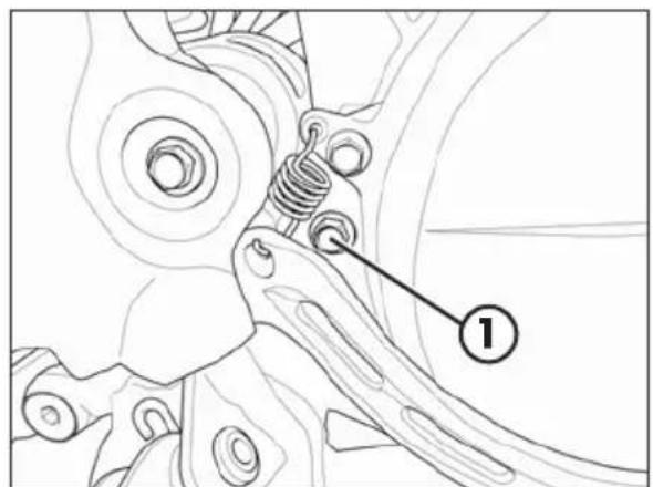
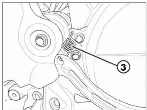
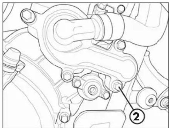
To facilitate this, it is recommended to remove spring 3.
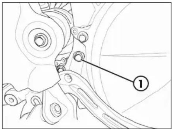
Push the brake caliper towards the inside of the vehicle.
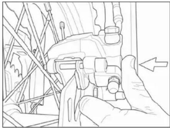
This way, screw 1 is uncovered.
Once this is completed, tighten screw 1 to 10Nm and reapply spring 3.

WARNING! Once completed, actuate the brake pedal repeatedly so as
to make the rear brake operational again.
4

REplacement
Always perform the replacement when engine is hot:
- Position the drive on a flat base ensuring stability.
- Remove the engine casing by loosening the screws shown in the figure.
- Place a container under the engine.
WARNING: Hot oil can cause severe burns! Screw on filler cap 1 again.
- Unscrew filler plug 1 and drain plug 2.
- Drain all the oil from the crankcase.
- Place the cap 2 and tighten to specified torque.
Pour in the quantity of liquid indicated on page 10.
Use the oil indicated on page 16 in the "Recommended lubricants and liquids" table.
WARNING:
Dispose of used oil in compliance with the regulations in force.
Screw on filler cap 1 again.
WARNING:
Dispose of used oil in compliance with the regulations in force.
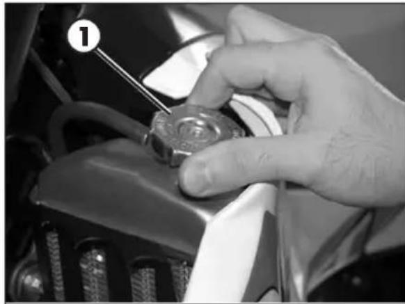
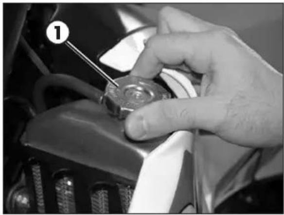
LIQUID COOLANT
CHECK THE LEVEL
Keep the vehicle in vertical position relative to the ground.
The level of the coolant must be checked when the engine is cold. Use the following procedure:
- Unscrew cap 1 and ensure that the liquid is visible in the lower portion of the loading tube.
- In the case in which the liquid is not visible remove the vent screw 2 and proceed topping up.
- At the end of operation refit the filler cap and the vent screw.
Use the oil indicated on page 16 in the "Recommended lubricants and liquids" table.

WARNING: Never unscrew the filler cap of the radiator when the engine is hot. Danger of burning!

WARNING:
Wear appropriate protective clothing and protection gloves.

Keep coolant out of reach of children.

Avoid any direct contact of the coolant with skin, eyes or clothing. If this happens:
with the eyes, rinse immediately with plenty of water and seek medical advice;
with skin, Immediately clean contaminated areas with soap and water Change clothing that is contaminated with coolant.
If coolant is swallowed, contact a doctor immediately.
4
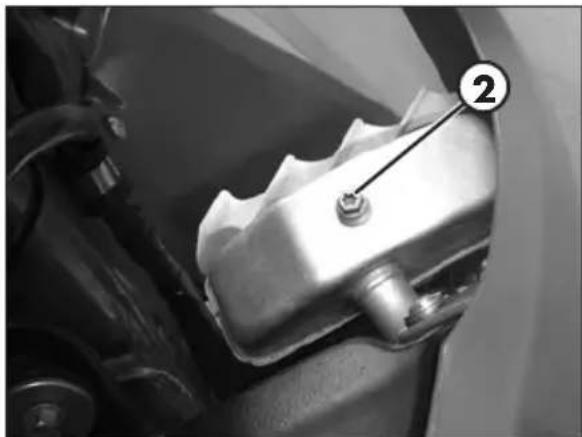
REplacement
Keep the vehicle in vertical position relative to the ground.
Replacement of the coolant must take place when the engine is cold.
- Unscrew cap 1.
-
Place a container under screw 2.
-
Unscrew the screw 2.
-
Drain the liquid.
-
Tighten screw 2 applying the specific washer.
- Unscrew drain screw 3.
- Proceed to filling.
When filling is completed, purge the engine group through the screw 4. After purging, verify the liquid level and top up if necessary.
When filling is completed, purge the motor group through the screw 4. After purging, verify the liquid level and top up if necessary.
- Reapply the loading cap and the bleeding screw.
The amounts of liquid are shown on page 16.
Use the liquid indicated on a page 16 in the "Recommended lubricants and liquids" table.

WARNING:
Never unscrew the filler cap of the radiator when the engine is hot. Danger of burning!

WARNING:
Wear appropriate protective clothing and protection gloves.

Keep coolant out of reach of children.

Avoid any direct contact of the coolant with skin, eyes or clothing. If this happens:
with the eyes, rinse immediately with plenty of water and seek medical advice;
with skin, Immediately clean contaminated areas with soap and water Change clothing that is contaminated with coolant.
If coolant is swallowed, contact a doctor immediately.
4
AIR FILTER
Check after every ride.
REMOVING AND INSTALLING AIR FILTER
To access the filter is necessary:
- Remove the saddle (page 82).
Pull the cover air filter (page 83).
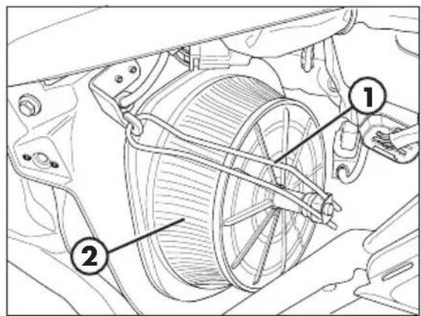
- Release filter fastener 1.
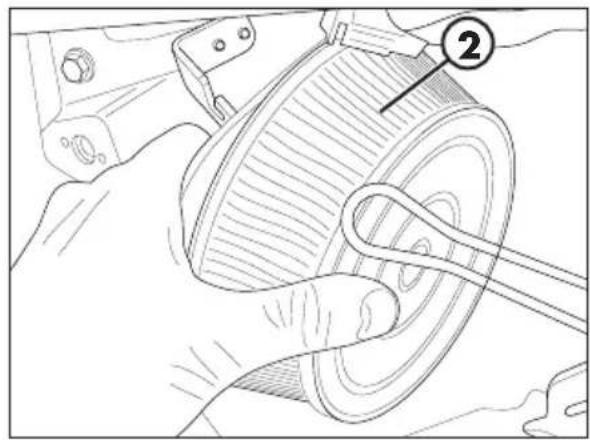
Pull out air filter 2.

WARNING:
After every intervention, check that nothing has been left inside the filter box.

NOTE:
If the filter is damaged, replace it immediately.
To replace, contact authorised Beta-motor customer service.

WARNING:
Never use the vehicle if the air filter is not in place. The infiltration of dust and dirt can cause damage and considerable wear.

WARNING:
After every intervention, check that nothing has been left inside the filter box.
Reassemble by performing the operations in reverse order.
AIR FILTER CLEANING - RR 125 EUROPE
Blow the filter with compressed air.
AIR FILTER CLEANING - RR 125
- Thoroughly wash the filter with water and soap.
- Dry the filter.
- Wet the filter with filter oil and then remove the excess oil to prevent it from dripping.
SPARK PLUG
Keeping the spark plug in good condition will reduce fuel consumption and increase engine performance.
To accede to spark plug, is necessary to take off the fuel tank with side fairings (page 83).
To perform the check, just extract the spark plug cap and unscrew the spark plug by means of the provided wrench.
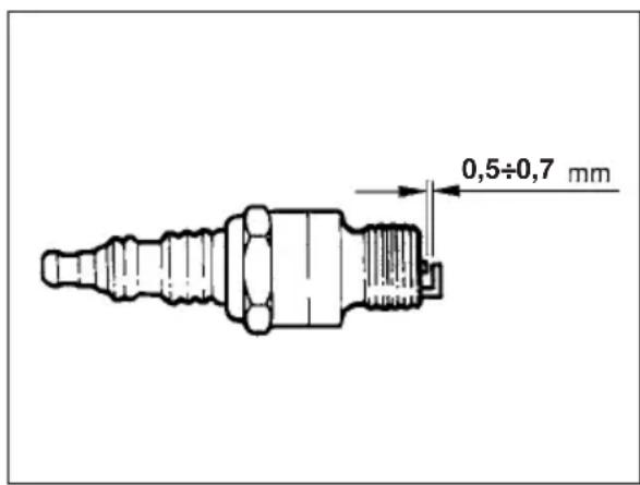
Carefully clean the electrodes using a wire brush. Blow the spark plug with compressed air to prevent any residues from getting into the engine.
Examine the distance between the electrodes with a feeler. This distance should be from 0,5 - 0,7mm . If it is not, it may be corrected by bending the earth electrode.
The spark plug may appear:
black fat" carburation
light brown appropriate carburation white "hin" carburation
Check as well that there are no cracks in the insulation or corroded electrodes. If so, replace immediately.
Lubricate the spark plug thread, and then (when the engine is cold) screw in the spark plug by hand to its abutting end. Finally tighten the spark plug with the spanner.

WARNING:
Do not check while the engine is hot.
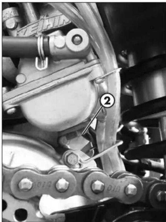
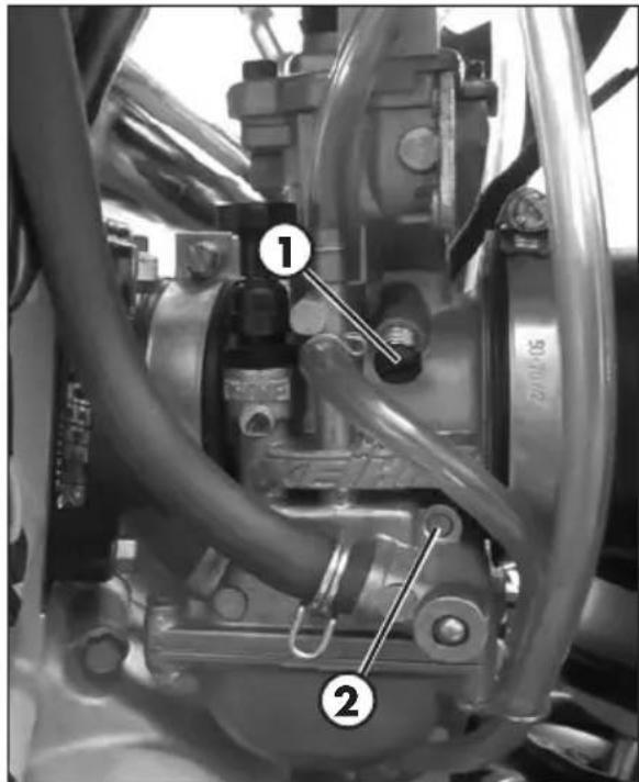
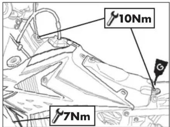
CARBURETTOR DRAINING THE CARBURETTOR FLOAT CHAMBER
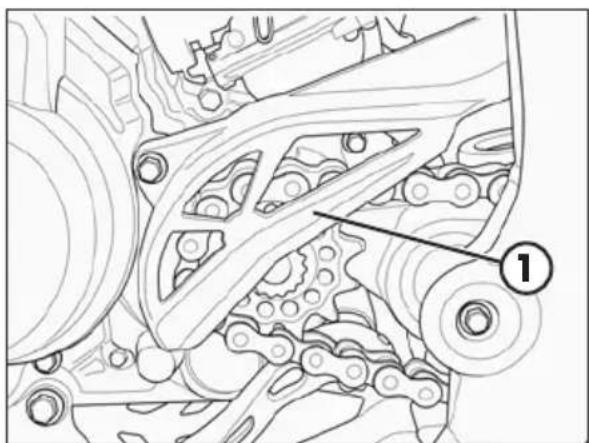
If the carburettor tank needs to be emptied, proceed as described.
Remove the chain protection 1, close the tank tap and put a cloth under the carburettor, so that you can collect the running out fuel.
Open the drain screw 2 to drain the fuel. Close the drain screw.
Apply the chain protection and tighten the screws at 10Nm.

WARNING:
Follow action on a cold engine.

WARNING:
Fire hazard. Fuel is highly flammable.

Always stop the engine when refuelling and keep open flames and lighted cigarettes away.
Refuel in an open well ventilated area.

Immediately clean up any spilled fuel.

WARNING:
Risk of poisoning!
Fuel is poisonous liquid and a health hazard.

Wear appropriate protective clothing and protection gloves.
Fuel must not come into contact with the skin, eyes, and clothing. Do not breathe in the fuel vapours. If contact occurs with the eyes, rinse immediately with plenty of water and seek medical advice. If contact occurs with skin, immediately clean contaminated areas with soap and water. If fuel is swallowed, contact a doctor immediately. Change clothing that is contaminated with fuel.
WARNING:
Environmental pollution hazard!
The fuel must not contaminate the ground water, the ground, or the sewage system.
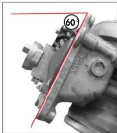
CHECKING THE FLOAT LEVEL
Remove the carburettor from the vehicle after following the procedure for emptying the carburettor bowl (page 56)
Remove the float chamber.
Keep the carburettor on a 60^ approx. inclined, so that float leans on the needle valve without pressing it.
In this position the float edge should be parallel with the float chamber sealing surface (see figure).
If the float height does not correspond to the nominal value, check the float needle valve and if necessary replace it.
If the needle valve is in working order, adjust the float height by bending float lever 1.
Assemble the carburettor tank, assemble the carburettor and check idling.
4
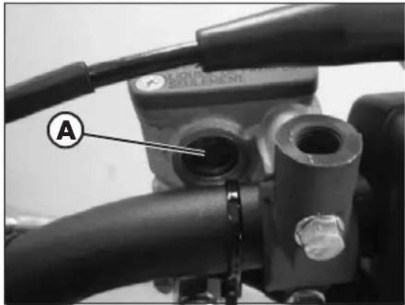
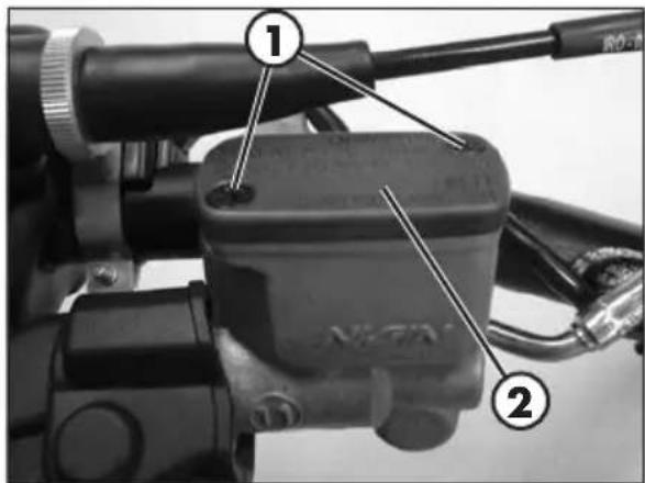
FRONT BRAKE
Check the level of the brake fluid through sight A. The level of the fluid should never fall below the mark in the sight.
To restore the level of the brake fluid, loosen the two screws 1, lift cap 2 and add brake fluid until its level is 5mm below the upper rim of the reservoir.
Use the liquid indicated on page 16 in the "Recommended lubricants and liquids" table.

WARNING:
The clutch fluid is extremely corrosive. Take care not to spill it on the paintwork.

Wear appropriate protective clothing and protection gloves.

Keep coolant out of reach of children.

WARNING: Avoid any direct contact of the liquid with skin, eyes or clothing. If this happens:
with the eyes, rinse immediately with plenty of water and seek medical advice.
with skin, immediately clean contaminated areas with soap and water. Change clothing that is contaminated with liquid.
If liquid is swallowed, contact a doctor immediately.
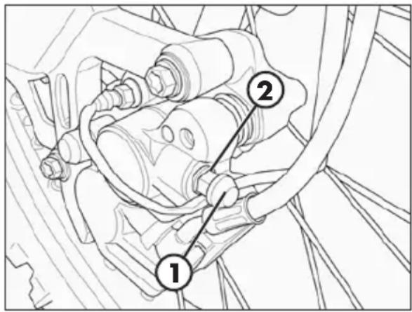
BLEEDING THE FRONT BRAKE
To bleed air from the front brake circuit, proceed as follows:
- Remove the rubber cap 1 from the valve 2.
- Open the sump cap.
- Place one end of a small transparent tube into the valve 2, and the other end inside a container.
- Pump with the brake lever 2/3 times and keep the lever pressed.
- Unscrew the valve and let the oil drain.
- If are still visible in the tube repeat above operation until obtaining a continuous outflow of oil within no air bubbles.
- Close the valve and release the lever.
NOTE:
during this procedure, continuously top up the brake pump thank to replace the oil that is out flowing.
- Remove the tube.
- Replace the rubber cap.
- Close the oil reservoir cap.
Use the liquid indicated on page 16 in the "Recommended lubricants and liquids" table.

WARNING:
The brake fluid is extremely corrosive. Take care not to spill it on the paintwork.

Wear appropriate protective clothing and protection gloves.

Keep coolant out of reach of children.

WARNING: Avoid any direct contact of the liquid with skin, eyes or clothing. If this happens:
- with the eyes, rinse immediately with plenty of water and seek medical advice.
- with skin, immediately clean contaminated areas with soap and water. Change clothing that is contaminated with liquid.
If liquid is swallowed, contact a doctor immediately.
4
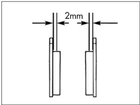
In order to verify the wear condition of front brake is enough to view the caliper from the bottom, where is possible to glimpse the brake lining tails which will have to show a brake of 2mm in thickness. If the stratum is lesser let's start replacing them.
Note:
Perform the check according to the times shown in the table on page 74.
To replace, contact authorised Betamotor customer service.
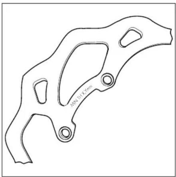
Periodically verify disc condition. In case signs of damage, veins, or deformations are present, proceed with replacement. Verify disc thickness. The minimum thickness is engraved on the disc.
Once the limit is in proximity or has been reached, proceed with brake disc replacement.
For replacement, contact an authorised Betamotor after-sales service centre.
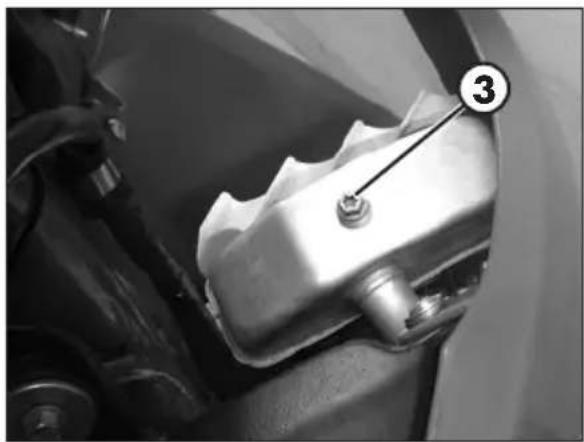
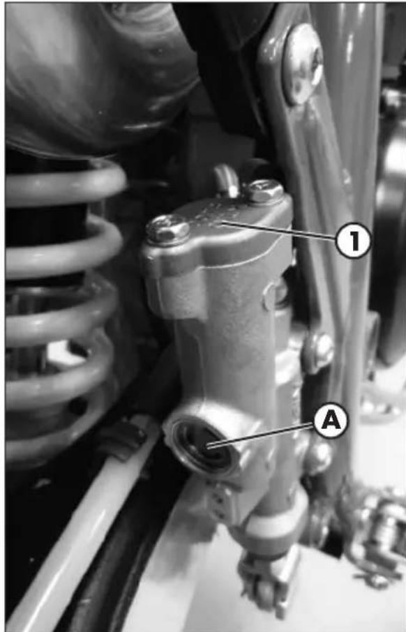
REAR BRAKE
Check the level of the brake fluid through sight A. The level of the fluid should never fall below the mark in the sight.
RESTORING THE LEVEL OF THE REAR BRAKE FLUID
To restore the oil level, top up by means of oil filler cap 1.
Use the liquid indicated on page 16 in the "Recommended lubricants and liquids" table.

WARNING:
The brake fluid is extremely corrosive. Take care not to spill it on the paintwork.

Wear appropriate protective clothing and protection gloves.

Keep coolant out of reach of children.

WARNING: Avoid any direct contact of the liquid with skin, eyes or clothing. If this happens:
with the eyes, rinse immediately with plenty of water and seek medical advice.
with skin, immediately clean contaminated areas with soap and water. Change clothing that is contaminated with liquid.
If liquid is swallowed, contact a doctor immediately.
4
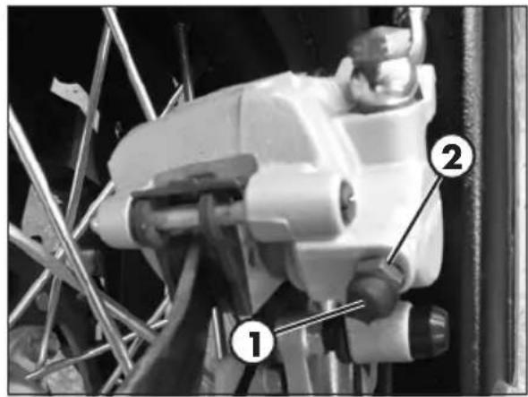
BLEEDING THE REAR BRAKE
To bleed air from the rear brake circuit, proceed as follows:
- Remove the rubber cap 1 from the valve 2.
- Open the sump cap.
- Place one end of a small transparent tube into the valve 2, and the other end inside a container.
- Pump with the brake lever 2/3 times and keep the pedal pressed.
- Unscrew the valve and let the oil drain.
- If are still visible in the tube repeat above operation until obtaining a continuous outflow of oil within no air bubbles.
- Close the valve and release the lever.
NOTE:
During this procedure, continuously top up the brake pump thank to replace the oil that is out flowing.
- Remove the tube.
-Replace the rubber cap. - Close the oil reservoir cap.
Use the liquid indicated on page 16 in the "Recommended lubricants and liquids" table.

WARNING:
The brake fluid is extremely corrosive. Take care not to spill it on the paintwork.

Wear appropriate protective clothing and protection gloves.

Keep coolant out of reach of children.

WARNING: Avoid any direct contact of the liquid with skin, eyes or clothing. If this happens:
- with the eyes, rinse immediately with plenty of water and seek medical advice.
- with skin, immediately clean contaminated areas with soap and water. Change clothing that is contaminated with liquid.
If liquid is swallowed, contact a doctor immediately.
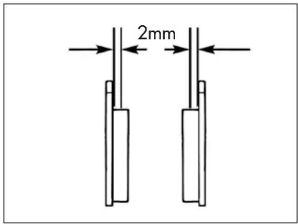
In order to verify the wear condition of rear brake is enough to view the caliper from above, where is possible to glimpse the brake lining tails which will have to show a brake of 2mm in thickness. If the stratum is lesser let's start replacing them.
Note:
Perform the check according to the times shown in the table on page 74.
To replace, contact authorised Betamotor customer service.
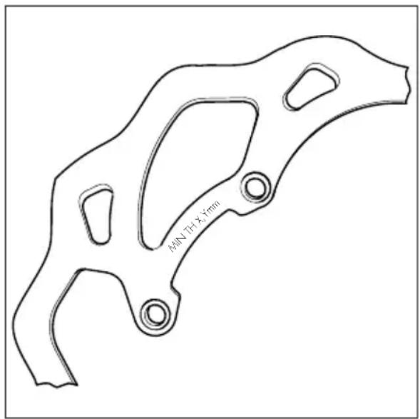
Periodically verify disc condition. In case signs of damage, veins, or deformations are present, proceed with replacement.
Verify disc thickness. The minimum thickness is engraved on the disc.
Once the limit is in proximity or has been reached, proceed with brake disc replacement.
For replacement, contact an authorised Betamotor after-sales service centre.
4
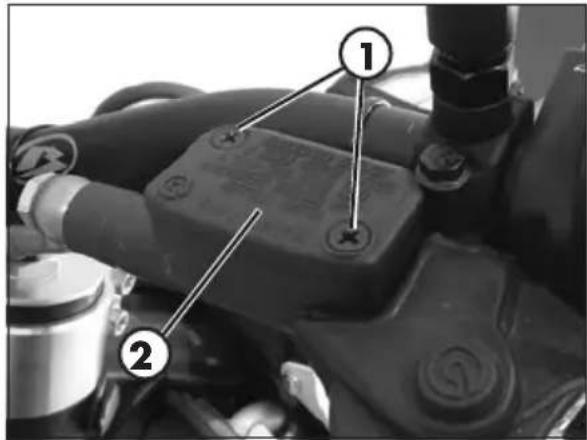
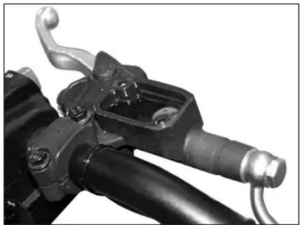
CLUTCH CONTROL CHECK THE LEVEL
To check the oil level in the clutch pump, first remove cover 2.
Remove the two screws 1 and take off cover 1 together with the rubber bellows. With the clutch pump in a horizontal position, the level of the oil should be 5mm below the upper rim.
In the case where the level is lower than specified top up.
Use the liquid indicated on page 16 in the "Recommended lubricants and liquids" table.

WARNING:
The clutch fluid is extremely corrosive. Take care not to spill it on the paintwork.

Wear appropriate protective clothing and protection gloves.

Keep coolant out of reach of children

WARNING: Avoid any direct contact of the liquid with skin, eyes or clothing. If this happens:
with the eyes, rinse immediately with plenty of water and seek medical advice.
with skin, immediately clean contaminated areas with soap and water. Change clothing that is contaminated with liquid.
If liquid is swallowed, contact a doctor immediately.
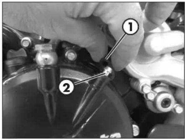
BLEEDING
To bleed air from the clutch pump, proceed as follows:
- Remove the rubber cap 1 from the valve 2.
- Open the sump cap.
- Place one end of a small transparent tube into the valve 2, and the other end inside a container.
- Pump with the clutch lever 2/3 times and keep the lever pressed.
- Unscrew the valve and let the oil drain.
If are still visible in the tube repeat above operation until obtaining a continuous outflow of oil within no air bubbles. - Close the valve and release the lever.
NOTE:
During this procedure, continuously top up the pump tank to replace the liquid that is out flowing.
- Remove the tube.
- Replace the rubber cap.
Use the liquid indicated on page 16 in the "Recommended lubricants and liquids" table.

WARNING:
The clutch fluid is extremely corrosive. Take care not to spill it on the paintwork.

Wear appropriate protective clothing and protection gloves.

Keep coolant out of reach of children.

WARNING: Avoid any direct contact of the liquid with skin, eyes or clothing. If this happens:
- with the eyes, rinse immediately with plenty of water and seek medical advice.
- with skin, immediately clean contaminated areas with soap and water. Change clothing that is contaminated with liquid.
If liquid is swallowed, contact a doctor immediately.
4
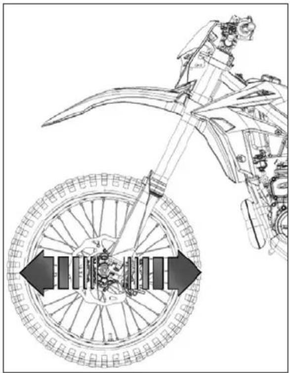
CHECK AND ADJUSTING OF STEERING PLAY
Periodically check the play in the steering sleeve by moving the fork back and forth as shown in the figure. Whenever you feel play, adjust as described below:
- Loosen the screws 1
- Loosen the screw 2
- Reduce the play by turning nut 3
Tighten the screws to the prescribed torque values.

WARNING:
Tightening of the screws should be carried out by adjusting the torque wrench to the stability torque with repeated tightening until stability torque has been achieved.
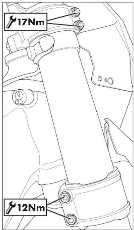
FORK
To maintenance refer at an authorized service centre Betamotor.
To check the tightening torques see as shown in the figure.

WARNING:
Tightening of the screws should be carried out by adjusting the torque wrench to the stability torque with repeated tightening until stability torque has been achieved.
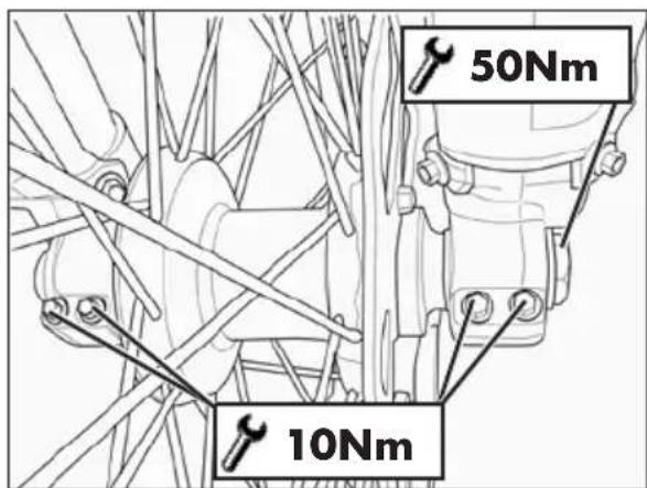
FRONT WHEEL
TIGHTENING
Following removal of the wheel:
Compress and release the fork 3-4 times.

Tighten the wheel bolt and the screws of the foot-leg.

WARNING:
Tightening of the screws should be carried out by adjusting the torque wrench to the stability torque with repeated tightening until stability torque has been achieved.
4
CHECKS AND MAINTENANCE
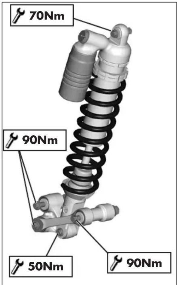
REAR SUSPENSION LEVERAGE
In order to guarantee optimal operation and duration over time of the progressive leverage of the rear suspension, it is recommended to periodically check correct tightness of nuts and bolts.
Verify that suspension nuts and bolts are at the indicated torque.
TYRES
Only fit tyres approved by BETAMOTOR.
Unsuitable tyres can adversely affect the road holding of the vehicle.
- To protect your safety, immediately replace any damaged tyres.
- Slick tyres adversely affect the road holding of the vehicle, especially on wet roads and in off-road riding.
Insufficient pressure results in abnormal wear and overheating of the tyres. - The front and rear tyres must have the same tread design.
- Always measure the inflating pressures when the tyres are cold.
- Keep the tyre pressures within the prescribed range.
CHAIN
Checking the drive chain periodically to ensure longer chain life. Always keep it lubricated and clean of deposited dirt.
Take special care in preventing the lubricant from coming into contact with the rear tyre or brake disc, otherwise the tyre grip and the action of the brake would be greatly reduced, making it very difficult to control the vehicle.
CHECK AND ADJUST TIGHTENING CHAIN
Position the drive on a flat base ensuring stability.
If the chain play exceeds 20mm tension the chain.
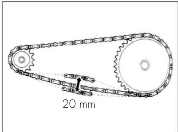
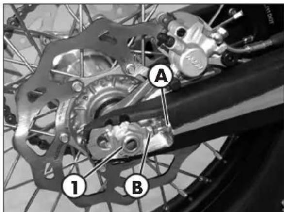
Loosen the pin 1.
4
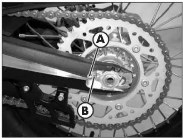
-
Loosen counternuts A on either side of the fork.
-
Turn adjusting screws B on either side until the desired chain tension is obtained.
-
Tighten counternuts A on either side of the fork.
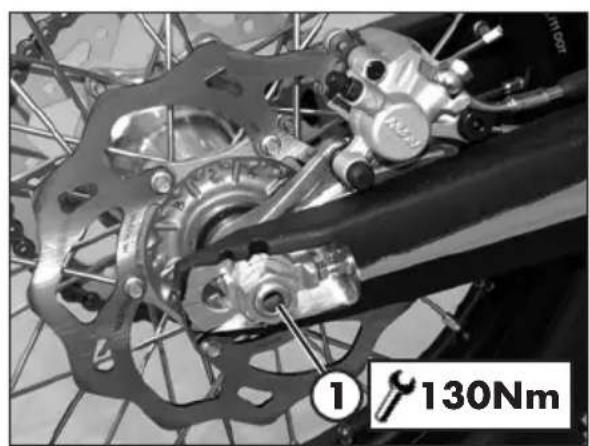
-
Tighten the pin 1 to the torque indicated.
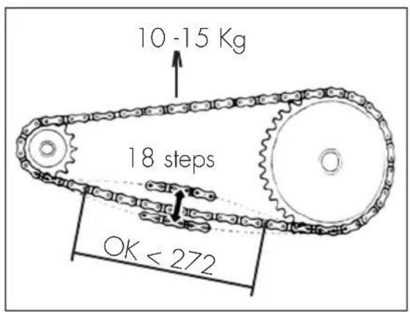
CHECK FOR CHAIN WEAR
Shift into neutral, pull up the upper stretch of the chain with a force of 10 - 15 kg (see figure). Measure the length of 18 links on the lower stretch of the chain. If the length is ≥ 272mm replace the chain. Chains do not always wear evenly. For this reason it is important that the measurement is taken at different points along the chain.
When fitting a new chain, be sure to replace the chainring and sprocket as well. New chains wear more quickly if fitted on old and worn sprockets. After replacing the chain, adjust its tension as described on page 69.
HEADLIGHT
Keep the headlight glass clean at all times (see page 72).
Periodically check the correct angle of the light beam.
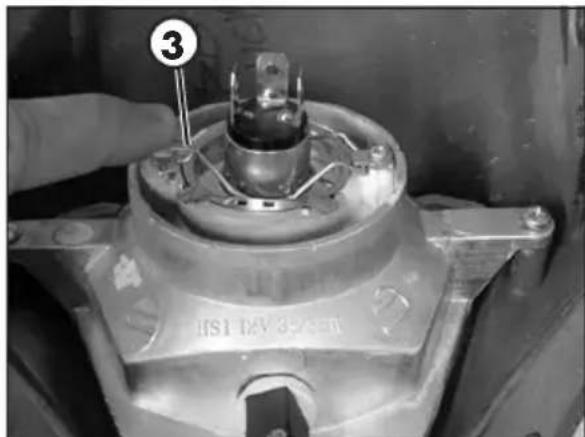
REPLACING THE HEADLIGHT BULBS
Remove the fixing screws and move forward the lamp holder front cowl.
Carefully remove the headlight bulb 1 together with lamp holder. To replace the high beam/low beam, lift the rubber cover 2, release connector, push on the spring 3 and remove the lamp holder and replace the light bulb with a new one. Be careful not to touch the bulb so as not to compromise its efficiency.
To refit, follow the procedure above but in reverse order.
Fasten the lamp holder front cowl to the supporting pins and fix it with the two elastics.
TAIL LIGHT
Keep the tail light glass clean at all times (see page 72).
The LED tail light is sealed. In the case of burnout of one or more LEDs it is necessary to replace the entire group.
To replace, contact authorised Betamotor customer service.

4 CLEANING THE VEHICLE
GENERAL PRECAUTIONS
WARNING: Do not clean your vehicle with a high-pressure device with a strong jet of water. Excessive pressure can reach electrical components, connectors, flexible cables, bearings, etc and can damage or destroy them.
WARNING: Wash motorbikes frequently with cold water that are used near the sea (salty air) and on roads subject to salt spreading in winter. Cover with a film of oil or silicone spray unpainted parts and the most exposed parts such as wheels, forks and swingarm. Do not treat rubber parts and brakes.
When cleaning, avoid direct exposure to sunlight.
Close off the exhaust system to prevent water from entering.
Avoid directing the jet of water onto the air filter box cover and the throttle body.
WASHING MODE
Use water jet to soften the dirt and mud accumulated on the paintwork, then remove them with a soft bodywork sponge soaked in water and shampoo. Subsequently rinse well with water, and dry with air and cloth or suede leather.
Detergents pollute water. Always wash the vehicle in areas equipped for collection and purification of the washing liquids.
AFTER WASHING
Proceed to the emptying of the filter box using the appropriate ventilation and drying.
After cleaning, ride a short distance until the engine reaches operating temperature.
WARNING: braking effect is reduced with wet brakes. Operate the brakes cautiously to allow them to dry.
Push back the handlebar control covers, so that water can evaporate.
When the bike is completely dry and cooled down, lubricate all moving parts.
Treat all plastic and painted components with non-aggressive detergents or products that are specific for the care of the motorcycle.
PROLONGED INACTIVITY
A few simple operations should be performed to keep the vehicle in good condition whenever it is to remain inactive for a long period (e.g. during the winter):
- Thoroughly clean the vehicle.
- Reduce the tyre pressures by approximately 30 percent, and if possible raise the tyres off the ground.
- Cover the unpainted parts, excepting the brakes and the rubber parts, with a film of oil or spray silicone.
- Protect the vehicle with a dust cover.
AFTER PROLONGED INACTIVITY
- Restore the tyre inflating pressures.
- Check the tightening of all the screws having an important mechanical function.
4
SCHEDUED MAINTENANCE VEHICLE
CHECKS AND MAINTENANCE
| Engine | ||||||||||||||||
| Gear and clutch oil | ||||||||||||||||
| Spark plug | ||||||||||||||||
| Head screws | ||||||||||||||||
| Engine clamping screws * | ||||||||||||||||
| Kick start and gearchange lever screws | ||||||||||||||||
| Spark plug cap | ||||||||||||||||
| Driving and driven clutch disks | ||||||||||||||||
| Clutch springs length | ||||||||||||||||
| Clutch/bell hub | ||||||||||||||||
| Gearbox bearing (drive shaft side) | ||||||||||||||||
| Cylinder | ||||||||||||||||
| Piston and segments | ||||||||||||||||
| Connecting rod | ||||||||||||||||
| Drive shaft bearings and seals | ||||||||||||||||
| Surface appearance of the gearbox | ||||||||||||||||
| Water pump oil seal | ||||||||||||||||
| Exhaust valve | ||||||||||||||||
| Reed valve | ||||||||||||||||
| Tightness | ||||||||||||||||
| dging setting | ||||||||||||||||
| Fuel pipe | ||||||||||||||||
| Breather pipe | ||||||||||||||||
| Exhaust manifold tightness | ||||||||||||||||
| Drives sliding and regulation | ||||||||||||||||
| Liquid level clutch pump | ||||||||||||||||
| Airbox and air filter | ||||||||||||||||
| Final transmission | ||||||||||||||||
| G | G | G | G | G | G | G | G | G | G | G | G | G | G | G | G | G |
| C | C | C | C | C | C | C | C | C | C | C | C | C | C | C | C | C |
| C | C | C | C | C | C | C | C | C | C | C | C | C | C | C | C | C |
| C | C | C | C | C | C | C | C | C | C | C | C | C | C | C | C | C |
| C | C | C | C | C | C | C | C | C | C | C | C | G | G | G | G | G |
| C | C | C | C | C | C | C | C | C | C | C | C | C | C | C | C | C |
Key
C Check (Clean, adjust, lubricate, replace as necessary)
S Replace/renew
R Adjust
P Clean
T Tighten
| End of running-in - 3 hours | Coupon 1 - 30 hours | Coupon 2 - 60 hours | Coupon 3 - 90 hours | Coupon 4 - 120 hours | Coupon 5 - 150 hours | Coupon 6 - 180 hours | |||||||||
| Brakes | Liquid level, pads thickness | C | C | C | C | C | C | C | C | C | C | C | C | C | |
| Disc thickness | C | C | C | C | C | C | |||||||||
| Pipe tightness | C | C | C | C | C | C | |||||||||
| Idle travel levers and drives sliding | C | C | C | C | C | C | C | C | C | C | C | C | C | ||
| Cycling | Shock absorber and telescopic fork | C | C | C | C | C | C | ||||||||
| Rear suspension linkage | C | C | C | C | C | C | |||||||||
| Fork cover | C | C | C | C | C | C | |||||||||
| Fuel lines | C | C | C | C | C | C | |||||||||
| Bearings of steering | C | C | C | C | C | C | |||||||||
| Bolts | TTTTTT | ||||||||||||||
| Wheels | Wheel spokes and rim coaxiality | C | C | C | C | C | C | ||||||||
| Tyres (wear and pressure) | C | C | C | C | C | C | |||||||||
| Bearings clearance | C | C | C | C | C | C | |||||||||
Key
C Check (Clean, adjust, lubricate, replace as necessary)
S Replace/renew
R Adjust
P Clean
T Tighten
| (*) Attachment Screw Threadlocker [Nm] | |||
| Engine to chassis | Special screw M10 | 45 | |
| Head brackets fastening front fixing | M8x16 M 35 | ||
| Head brackets fastening rear fixing | M8x60 35 | ||
| Brackets to attach the head to the engine | M8x16 M 35 | ||
WARNING:
For any service requirements, please contact Betamotor's Authorized Service Network.
TIGHTENING TORQUE OVERVIEW
Here below is an overview of the tightening torque of all pieces subject to adjustment or maintenance:
| Forecarriage | ||
| Tightening torque [Nm] Threadlock | ||
| Wheel pin 50 | ||
| Fork foots - wheel pin 10* | ||
| Brake caliper - Fork 35 M | ||
| Cavallotto parastelo sinistro 1,5 | ||
| Steering head base - fork legs 12* | ||
| Steering head - fork legs 17* | ||
| Stem pin on steering head 20 | ||
| Lower handlebar u-bolt - steering head 40 M | ||
| Upper handlebar u-bolt - lower handlebar u-bolt | 25 | |
| Rear axle | ||
| Tightening torque [Nm] Threadlock | ||
| Wheel pin 130 | ||
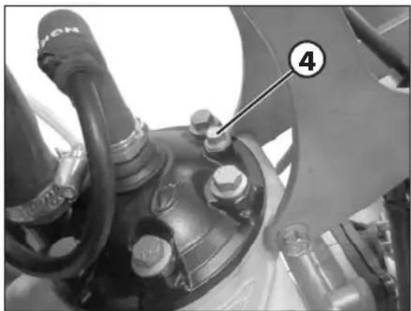
| Rear shock absorber - frame 70 M | ||
| Rear shock absorber - rocker arm 50 | ||
| Connecting rod - frame 90 | ||
| Connecting rod - rocker arm | 90 | |
| Rocker arm - swinging arm | 90 | |
| Engine | ||
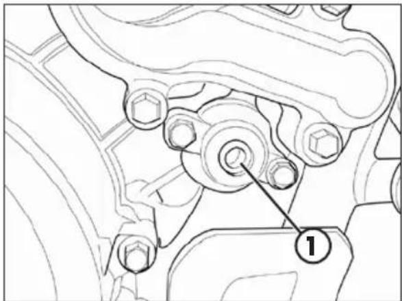
| Tightening torque [Nm] | Threadlock | |
| Gearbox oil drain plug | 15 | |
| Engine - Frame | ||
| Tightening torque [Nm] | Note | |
| Pins motor - frame | 45 | |
| Brackets to attach the head - frame (front fixing) | 35 | M |
| Brackets to attach the head - frame (rear fixing) | 35 | |
| Brackets to attach the head - motor | 35 | M |
M Medium strength threadlock

WARNING:
Tightening of the screws should be carried out by adjusting the torque wrench to the stability torque with repeated tightening until stability torque has been achieved.
CHAPTER 5 REMOVING AND INSTALLING SUPERSTRUCTURES
CONTENTS
Removing and installing of the saddle. 78
Removing and installing air filter side panel. 79
Removing and installing of the complete tank. 79
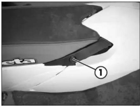

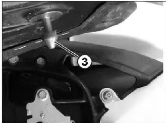
REMOVING AND INSTALLING OF THE SADDLE
Press button 1.
Remove the saddle towards the rear of the motorcycle.
To re-assemble: Insert the cavity 1 of the saddle in slot 2.
Press the saddle down in the middle and at the same time, push it forwards until the bayonet joint engages in its seat.

WARNING
Make sure the bayonet joint 3 is firmly inserted into the button lock.
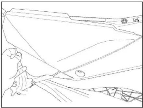
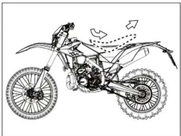
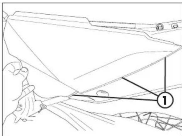
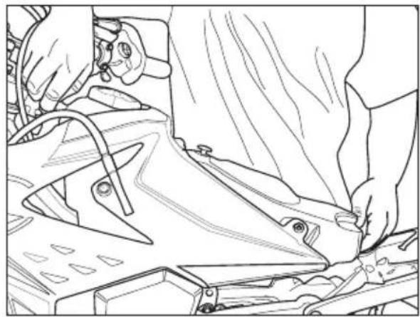
REMOVING AND INSTALLING AIR FILTER SIDE PANEL
Remove the saddle (page 78).
Grab the side panel in the front side and pull out.
To refit insert the tabs 1 into their slots.
Slide the side panel toward the vehicle.
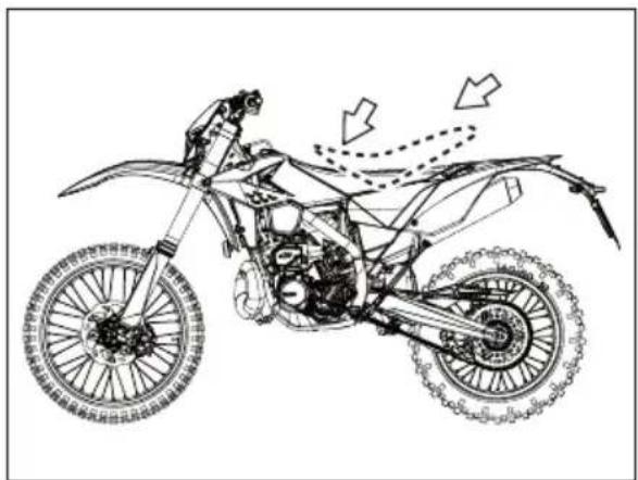
REMOVING AND INSTALLING OF THE COMPLETE TANK
Disconnect the fuel tank vent pipe.
Turn the fuel cock to OFF position (page 18) and disconnect the fuel hose from the fuel cock.

WARNING:
Follow action on a cold engine.

WARNING:
Fire hazard. Fuel is highly flammable.

Always stop the engine when refuelling and keep open flames and lighted cigarettes away.

Immediately clean up any spilled fuel.
Remove the air filter side panel (page 79).

Remove the two screws 1 fastening the tank to the frame and the screw 2 (one per side) securing the fairing to the radiator.
Lift the tank complete with side panels.
Replace the previously removed components following the disassembly procedures inversely.
Tighten the tank screws to the torques given.
CHAPTER 6 TROUBLESHOOTING
CONTENTS
Troubleshooting 82
TROUBLESHOOTING
| PROBLEM CAUSE REMEDY | ||
| Engine does not start | Fuel system clogged (fuel lines, fuel tank, fuel cock) | Contact authorised BETAMOTOR customer service |
| - Air filter dirty Check the air filter | ||
| -No current supplied to spark plug | Clean or replace the spark plug. If the problem persists, contact authorised BETAMOTOR customer service | |
| - Engine flooded Operate the electrical act | al starter push button 2 times for 5 seconds. If the vehicle does not start, remove and dry the spark plug | |
| - Excessive distance between the electrodes | Check the distance between the electrodes | |
| - Ignition connector or coil slackened or oxidized | Clean with a spray product for electric contacts and tighten | |
| - Presence of water in the carburettor Empty the carburettor tank | ||
| The engine starts but the telltale "MIL" lights on | - Engine management system fault Cont | act authorised BETAMOTOR customer service |
| "High Voltage" appe-ars on the instrument | - Overcharging | Turn off the engine and contact authorised BETAMOTOR customer service |
| Engine misfires | - Spark gap wrongly adjusted Restore the spark gap | |
| - Spark plug dirty Clean or replace the spark plug | ||
| The engine does not hold idling | - Idling air jet clogged Contact authorised | BETAMOTOR customer service |
| - Adjustment screws poorly adjusted | Adjust | |
| - Faulty spark plug Replace the spark plug | ||
| - Faulty ignition system | Check the coil and the spark plug cap | |
| Engine overheats and loses power | - Silencer partly clogged | Contact authorised BETAMOTOR customer service |
| - Laminar pack damaged | Contact authorised BETAMOTOR customer service | |
| - Fault in the ignition system | Contact authorised BETAMOTOR customer service | |
| Excessive smoke - Possible mixer system fault Cont | Contact authorised BETAMOTOR customer service | |
| Front braking poor | - Brake pads worn Contact authorised | BETAMOTOR customer service |
| - Air or humidity in the hydraulic circuit | Follow the procedure described on page 59 | |
| Rear braking poor | - Brake pads worn Contact authorised | BETAMOTOR customer service |
| - Air or humidity in the hydraulic circuit | Follow the procedure described on page 62 | |
CHAPTER 7 INSTRUCTIONS FOR PERIODIC REVIEW WORKSHOPS
CONTENTS
Instructions for periodic review workshops. 84
Alphabetical index 86
INSTRUCTIONS FOR PERIODIC REVIEW WORKSHOPS
Instructions for periodic review workshops, in accordance with EU regulation 2019/621.
| 1. BRAKING EQUIPMENT | ||
| ITEM/ASSEMBLY REFERENTIE | IN DE DOCUMENTATIE OPMERKINGEN | |
| 1.1.13. Brake linings and pads CHAP. 4-CHECKS AND MAINTENANCE;PARAGRAPHS "FRONT BRAKE LININGCONTROL", "REAR BRAKE LINING CONTROL" | ||
| 1.6. AntiHock braking system (ABS) NOT PRESENT | ||
| 2. STEERING | ||
| 2.2.2. Steering column, forks and steering dampers | STEERING DAMPER NOT PRESENT | |
| 4. LAMPS, REFLECTORS AND ELECTRICAL EQUIPMENT | ||
| 4.1. Headlamps | ||
| 4.1.1. Condition and operation CHAP. 1 - GENERAL INFORMATION;PARAGRAPH "BULBS" | ||
| 4.1.2. Alignment NOT PRESENT | ||
| 4.1.3. Switching CHAP. 2 - OPERATION;PARAGRAPH "LH SWITCH" | VEHICLE ELECTRONIC INTERFACE ABSENT | |
| 4.1.5. Levelling devices (where mandatory) | NOT MANDATORY | |
| 4.2.1. Condition and operation INSTALATION OF DAYTIME | RUNNING LIGHTS PRESENT | |
| 4.11. Electrical wiring CHAP. 1 - GENERAL INFORMATION;PARAGRAPH "ELECTRICAL DIAGRAM" | ||
| 4.13. Battery NOT PRESENT | ||
| 5. AXLES, WHEELS, TYRES AND SUSPENSION | ||
| 5.1.1. Axles TWO-AXIS | ||
| 5.2.2. Wheels CHAP. 1 - GENERAL INFORMATION;PARAGRAPH "WHEELS" | ||
| 5.2.3. Tyres | CHAP. 1 - GENERAL INFORMATION;PARAGRAPH "TYRES" | |
| 6. CHASSIS AND CHASSIS ATTACHMENTS | ||
| 6.1.3. Fuel tank and pipes (including heating fuel tank and pipes) | CHAP. 1 - GENERAL INFORMATION; PARAGRAPH "FAMILIARIZING WITH THE VEHICLE" CHAP. 2 - OPERATION; PARAGRAPHS "FUEL TANK CAP", "FUEL COCK", "MIXER OIL TANK CAP" (IF PRESENT) | |
| 6.1.9. Engine performance NOT AVAILABLE | ||
| 7. OTHER EQUIPMENT | ||
| 7.11. Odometer if available CHAP. | 2 - OPERATION; PARAGRAPH "DASHBOARD OPERATING INSTRUCTIONS" | VEHICLE ELECTRONIC IN-TERFACE ABSENT |
| 8. NUISANCE | ||
| 8.1.1. Noise suppression system SEE | SUMMARY PLATE ON BOARD | |
| 8.2.1.2. Gaseous emissions NOT | APPLICABLE TO | 2-STROKE ENGINES |
ALPHABETICAL INDEX
Adjusting fork 43
Adjusting the idle speed. 39
Adjustment of gas clearance 39
Air filter 54
Brakes 38
Bulbs 16
Carburettor 56
Chain 69
Check and adjusting of steering play. 66
Checks before and after use 33
Cleaning the vehicle 72
Clutch 38
Clutch control 64
Digital rpm indicator operating instructions. 23
Electrical system 14
Engine oil 48
Engine shut-down 35
Exhaust valve control adjustment 42
Familiarizing with the vehicle. 9
Fork 67
Front brake 58
Front wheel 67
Handlebar adjustment 42
Headlight. 71
Instructions for periodic review workshops. 84
Key to symbols. 38
Key to symbols. 48
Liquid coolant 51
Main parts 18
Operating instructions. 5
Prolonged inactivity 73
Rear brake 61
Rear suspension leverage 68
Recommended lubricants and liquid 16
Refuelling 34
Removing and installing air filter side panel. 79
Removing and installing of the complete tank. 79
Removing and installing of the saddle. 78
Replacing the headlight bulbs. 71
Riding safety 6
Running in 33
Scheduled maintenance vehicle 74
Shock absorber 44
Spark plug 55
Specifications 10
Starting the engine 35
Symbols 5
Tail light 71
Tightening torque overview 76
Tools kit 8
Troubleshooting 82
Tyres. 68
Vehicle identification data 8

RR 125 2T EUROPE - RR 125 2T
WECHSELSCHALTER RECHTS
ESTÁ PROHIBIDO FUMAR
ESTA PROHIBIDO EL USO DEL TELEFONO MOVIL
PELIGRO DEBIDO A LA PRESENCIA DE SUSTANCIAS CORROSIVAS
HFDST. 1 ALGEMENE INFORMATIE
INHOUD THEMA'S
Framenummer 8
Motoridentification 8