IS 330 EB - Saw FESTOOL - Free user manual and instructions
Find the device manual for free IS 330 EB FESTOOL in PDF.
Download the instructions for your Saw in PDF format for free! Find your manual IS 330 EB - FESTOOL and take your electronic device back in hand. On this page are published all the documents necessary for the use of your device. IS 330 EB by FESTOOL.
USER MANUAL IS 330 EB FESTOOL
EU Declaration of Conformity. We declare under sole responsibility that this product complies with all the relevant requirments in the following EU Directi- ves, and following standards or normative documents were applied:
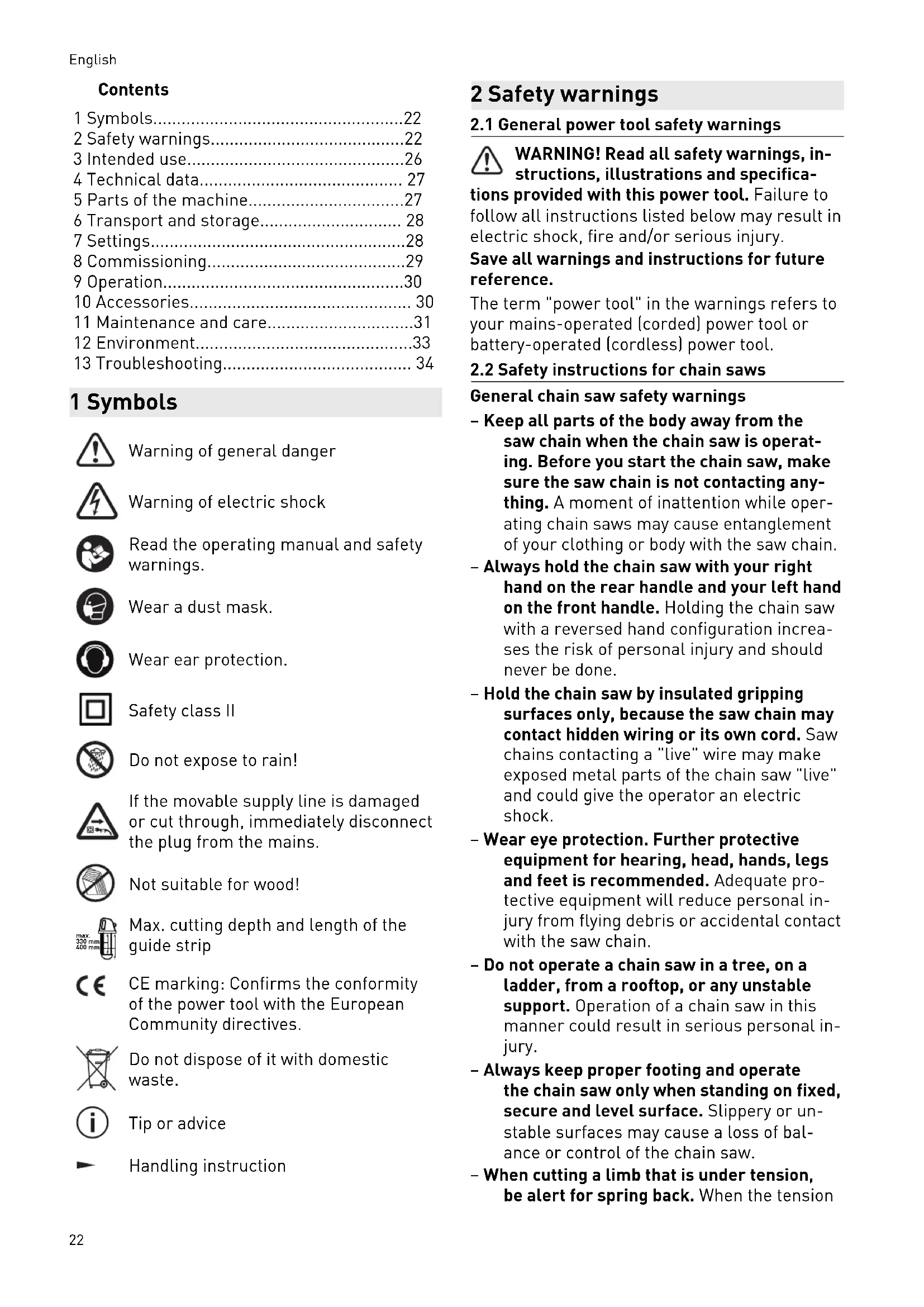
2.1 General power tool safety warnings
WARNING! Read all safety warnings, in structions, illustrations and specifica tions provided with this power tool. Failure to follow all instructions listed below may result in electric shock, fire and/or serious injury. Save all warnings and instructions for future reference. The term "power tool" in the warnings refers to your mains-operated (corded) power tool or battery-operated (cordless) power tool.
2.2 Safety instructions for chain saws
General chain saw safety warnings – Keep all parts of the body away from the saw chain when the chain saw is operat ing. Before you start the chain saw, make sure the saw chain is not contacting any thing. A moment of inattention while oper ating chain saws may cause entanglement of your clothing or body with the saw chain. – Always hold the chain saw with your right hand on the rear handle and your left hand on the front handle. Holding the chain saw with a reversed hand configuration increa ses the risk of personal injury and should never be done. – Hold the chain saw by insulated gripping surfaces only, because the saw chain may contact hidden wiring or its own cord. Saw chains contacting a "live" wire may make exposed metal parts of the chain saw "live" and could give the operator an electric shock. – Wear eye protection. Further protective equipment for hearing, head, hands, legs and feet is recommended. Adequate pro tective equipment will reduce personal in jury from flying debris or accidental contact with the saw chain. – Do not operate a chain saw in a tree, on a ladder, from a rooftop, or any unstable support. Operation of a chain saw in this manner could result in serious personal in jury. – Always keep proper footing and operate the chain saw only when standing on fixed, secure and level surface. Slippery or un stable surfaces may cause a loss of bal ance or control of the chain saw. – When cutting a limb that is under tension, be alert for spring back. When the tension English 22in the wood fibres is released, the spring loaded limb may strike the operator and/or throw the chain saw out of control. – Use extreme caution when cutting brush and saplings. The slender material may catch the saw chain and be whipped toward you or pull you off balance. – Carry the chain saw by the front handle with the chain saw switched off and away from your body. When transporting or storing the chain saw, always fit the guide bar cover. Proper handling of the chain saw will reduce the likelihood of accidental contact with the moving saw chain. – Follow instructions for lubricating, chain tensioning and changing the bar and chain. Improperly tensioned or lubricated chain may either break or increase the chance for kickback. – Cut wood only. Do not use chain saw for purposes not intended. For example: do not use chain saw for cutting metal, plas tic, masonry or non-wood building materi als. Use of the chain saw for operations dif ferent than intended could result in a haz ardous situation. – This chain saw is not intended for tree felling. Use of the chain saw for operations different than intended could result in seri ous injury to the operator or bystanders. Causes and operator prevention of kickback Kickback may occur when the nose or tip of the guide bar touches an object, or when the wood closes in and pinches the saw chain in the cut. Tip contact in some cases may cause a sudden reverse reaction, kicking the guide bar up and back towards the operator. Pinching the saw chain along the top of the guide bar may push the guide bar rapidly back towards the operator. Either of these reactions may cause you to lose control of the saw which could result in serious personal injury. Do not rely exclusively upon the safety devices built into your saw. As a chain saw user, you should take several steps to keep your cutting jobs free from accident or injury. Kickback is the result of chain saw misuse and/or incorrect operating procedures or con ditions and can be avoided by taking proper precautions as given below: – Maintain a firm grip, with thumbs and fin gers encircling the chain saw handles, with both hands on the saw and position your body and arm to allow you to resist kickback forces. Kickback forces can be controlled by the operator, if proper pre cautions are taken. Do not let go of the chain saw. – Do not overreach and do not cut above shoulder height. This helps prevent unin tended tip contact and enables better con trol of the chain saw in unexpected situa tions. – Only use replacement guide bars and saw chains specified by the manufacturer. In correct replacement guide bars and saw chains may cause chain breakage and/or kickback. – Follow the manufacturer’s sharpening and maintenance instructions for the saw chain. Decreasing the depth gauge height can lead to increased kickback.
2.3 Further safety instructions
– Only ever use the power tool for its inten ded use. Using the power tool as a station ary saw is prohibited. – Unauthorised persons are forbidden from touching the power tool and its electric supply line. – Always adhere to the applicable regula tions regarding safety at work. – Use appropriate detection devices to look for any hidden supply lines or consult your local utility company. If the insertion tool makes contact with live cables, it can result in fire and electric shock. Damage to a gas pipe can lead to an explosion. Penetration of a water pipe can result in damage to property. – Wear protective goggles and ear protection that comply with national regulations for personal protective equipment when work ing. Wear a cut protection overall or cut protection trousers. Wear sturdy footwear with non-slip soles. Do not wear loose jack ets, scarves, jewellery, etc. that can get caught in the saw chain. – To comply with the safety class, you must check the saw for safety. This is why you must commission a specialist electrotech nical workshop to perform this work. – We recommend using a residual current device with a tripping current of 30 mA or less. – Only the permitted and appropriately marked extension cables must be used English 23outdoors. The extension cable must be checked regularly and replaced immedi ately in the event of damage. – Be aware of environmental factors. Do not leave the power tool out in the rain and do not use it in a humid or wet environment. Ensure the work area is well lit and do not use the power tool near flammable liquids and gases. When warm, the power tool must not be put down where it could catch fire and it must be kept clean. – Regularly check the movable supply line and, in the event of damage, have it re placed in a specialist workshop. Do not use the movable supply line to carry the power tool or to pull the plug out of the socket. The cable must be protected from high temperatures, oil and movement over sharp edges. – Before using the power tool, always check all guards, elements and moving parts. All parts must be attached correctly and all conditions for correct operation of the pow er tool must be met. Damaged guards and elements must be repaired or replaced properly in an authorised workshop. Dam aged switches must be replaced by an au thorised workshop. Do not use the power tool if the switches cannot be switched on or off. – Prevent the switch from jamming in the ON position. – Take good care of the tools. Using sharp and clean tools is the only way to work more effectively and safely. Defective, blunt tools or tools with unsuitable dimensions must not be used. Note the instructions for tool maintenance and tool replacement. – Never use blunt or damaged chains. Using blunt or incorrectly set chains results in a higher load, which can destroy the power tool and subsequently cause injuries. – Only use accessories or special accesso ries that are recommended by the manu facturer. – The guard plate must not be removed or modified. – The guard plate is an integral part of the power tool. You must not adapt, shorten or remove it. Ensure that it is at the level of the guide strip, that the chain tension is correct and that it does not touch the guard plate. The minimum distance between the chain and the guard plate is 5 mm. – For the guard plate to work, it must be positioned in the cut groove. The guard plate does not prevent kickback when saw ing saw cuts. – If the guard plate is bent, do not use the saw. – As a general rule, the guards and protec tive devices must not be removed and they must not be prevented from working prop erly. – Only ever use chain saw bars, chains and chain sprockets that have been recom mended by the manufacturer. The chain saw bar must always be properly secured. – Chains with teeth for stationary power tools must not be used. – Do not saw workpieces that are too large or too small for the power tool. – Plunge cuts are not possible at all as the guard plate assembly does not allow them. Removing the guard plate is prohibited. – Making a groove or recess (plunging) into solid, sealed surfaces with the tool running is prohibited. Risk of injury from power tool kickback! – When the power tool is not being used or when the tool is being repaired or replaced, pull the plug of the movable supply line out of the socket. – Only for AS/NZS: The tool shall always be supplied via residual current device with a rated residual current of 30 mA or less. Before starting – Ensure your work area is tidy. An untidy work area can cause accidents at work. – Always lay the movable supply line in such a way that it cannot be caught by the tool and does not pose an additional hazard, e.g. tripping. – When operating the power tool in an en closed space, ensure sufficient ventilation or use a dust extraction system. Do not saw hazardous materials, such as asbestos. – Before you start work, check the lubricat ing oil level and that the lubrication system is working properly. – Check that the original chain sprocket cov er is complete. If the original chain sprock et cover is incomplete or damaged, it must not be used. It must not be replaced with other components either, e.g. with nuts. The tensioning system was specially de English 24signed for your saw to ensure optimal func tionality and safety when working. – Before you start sawing, tighten the adjust ing levers for tilting and angle adjustment of the guide strip sufficiently and reliably. If the position of the guide strip is readjusted during sawing, this can cause jamming and kickback. – Remove all foreign particles from the ma terial to be cut, especially metal, which could damage the tool and lead to injury. – Before switching on the power tool, check that the guide strip is secured properly and that the chain tension is correct. – The correct chain tension is important. Check the chain tension before starting work and continuously while you work. Choose a chain rate of advance so that the chain does not stop. – Do not switch on the power tool until it has been placed on the workpiece to be cut. Only start sawing once the power tool has reached maximum speed. During work – During sawing, the selected cutting direc tion must not be changed using force. – Ensure that you keep your hands at a safe distance from the cutting area and the chain. Hold the additional hand grip firmly in your other hand. If you hold the saw in both hands, you cannot experience any hand injuries. – Never hold a workpiece in your hand or support it with your knee during cutting. The workpiece must be secured on a solid surface. It is important that the workpiece to be cut is properly supported to minimise the risk of any part of your body coming in to contact with it, the chain jamming or a loss of control. – Do not reach under the material being cut. The guard plate does not provide sufficient protection against contact with the chain under the workpiece being cut. – If you are sawing large boards or sheets, ensure a good support to prevent the chain jamming and kickback. Large boards or sheets tend to bend or bow under their own weight. The support must be fitted under the board or sheet on both sides of the cut and near the edges of the board or sheet. – For rip cuts, always use the guide rail and/or the parallel side fence. This im proves the cutting accuracy and reduces the risk of the chain jamming. – If the chain is twisted or not aligned in the cut, the teeth on the rear edge of the chain may hit against the wooden surface from above, causing the chain to jump out of the cut and jerking the saw back towards the user. – If the chain becomes jammed or if it be comes necessary to release the chain for any other reason, switch the saw off imme diately and hold the saw in the material un til the chain comes to a complete stop. Never attempt to lift the saw out of the cut or to withdraw it when the chain is not sta tionary as this can cause kickback. Try to ascertain the causes of the chain jam and the solution for rectifying the causes. – When restarting the saw with the chain in the workpiece, centre the chain in the cut and ensure that the teeth are not in contact with the material. If the chain is jammed, it may jump out of the workpiece or cause kickback after the saw is restarted. – Caution during chip ejection! If the chip ejector is blocked, switch off the power tool and pull the supply line out of the socket. You can only remove the chain sprocket cover and clean the blocked opening once the chain has come to a stop. Do not reach into the chip ejector unless the power tool is completely still. – The power tool must only be removed from the workpiece to be cut once the chain has come to a stop. – After finishing the cut and switching off the power tool, it must be kept in the working position until it has come to a complete stop. – We recommend placing the power tool down on the guide table or Systainer. This way, you avoid any damage to the chain and the chain guide strip. – Before you place the saw on the workbench or the floor, always check that the chain has stopped and that the saw is resting against the guard plate. If the chain is not protected and runs on, this will cause kick back and will saw everything it comes into contact with. Take into consideration the time required for the chain to come to a stop after the power tool is switched off. We recommend placing the saw down level on the guide table or the Systainer. English 25– If the power tool is not being used, always attach the guard to the chain; this also ap plies when carrying the power tool. – Never carry the power tool with the chain running. – When not in use, the power tool must be kept in a safe, dry and locked place, out of the reach of children and unauthorised persons.
Even when the power tool is used as per the recommendations and all safety instructions have been adhered to, the design engineering of the power tool and its use mean that the follow ing safety risks may arise: – Injury at teeth when replacing the chain. – Injury when touching the chain in the cut ting area. – Clothing drawn in by running chain. – Injury from saw offcuts or tool parts flying off. – Danger caused by movable supply cable. – Kickback from chain jamming or working with the point of the strip. – Hazardous concentration of dust when working in rooms with insufficient ventila tion. – Injury caused by touching live parts when disassembling the power tool or its parts if the mains plug of the movable supply line has not been removed from the socket. – Hearing damage when working for pro longed periods without hearing protection.
The levels determined in accordance with EN 62841 are typically: Sound pressure level L
= 102 dB(A) Uncertainty K = 3 dB CAUTION Noise generated when working Risk of damage to hearing ► Use ear protection. Vibration emission level a
(vector sum for three directions) and uncertainty K measured in accordance with EN 62841: The hand/arm vibration is typi cally
The specified emission levels (vibration, noise) – are used to compare machines. – They are also used for making preliminary estimates regarding vibration and noise load during operation. – They represent the primary applications of the power tool. CAUTION The emission values may deviate from the specified values. This is dependent on how the tool is used and the type of workpiece being machined. ► Assess the actual load during the entire operating cycle. ► Depending on the actual load, suitable pro tective measures must be defined in order to protect the operator. 3 Intended use CAUTION Not suitable for wood! The power tool is only suitable for sawing pressure-resistant insulating materials. Different chain types make it possible to choose the right tool for sawing pressure- resistant insulating materials of any densi ty.
3.1 Description of the power tool
The IS 330 EB insulation saw is intended for sawing insulating materials based on wood fi bre and PU foam. This power tool can be used to saw at a right angle and at an adjustable an gle up to a depth of 330 mm. The cutting angle can be adjusted quickly and easily up to 60° using two swivelling segments and an easy-to-read scale. The power tool fea tures an extendable parallel side fence, which can be used on both sides of the guide block and ensures an accurate, straight cut. The guide strip can be quickly tilted 10° backwards. The chain is tensioned simply and without the use of tools by means of the tensioning wheel, which is easily accessible at the top of the main handle. The chip ejector opening ensures relia ble chip evacuation out of the power tool and makes it possible to use a dust extractor. While sawing, the chain is optimally lubricated by the oil feed pump. After switching on the power tool, the motor starts up gradually until English 26it reaches the maximum speed, controlled by the electronic control unit. The electronics pro tect the motor. The motor is switched off auto matically if it experiences sudden overload. If overloaded for a longer period, it switches to "cooling mode", during which the power tool runs at a low cooling speed and, once cooled, it returns to the normal operating mode. When the power tool is switched off, the electronic brake is activated at the same time, which sig nificantly shortens the chain run-on time. The run-on time may vary greatly depending on the set speed.
The insulation saw is designed to saw insulating materials. The power tool is operated by one person who holds and guides it by the handles provided, i.e. at the front additional hand grip and at the rear handle. Holding the power tool at the rear addi tional hand grip is only permitted if there is no risk of kickback. Any other use of this power tool is regarded as improper use. The power tool is not intended for sawing wood, for felling trees or for cutting trees and bushes. The manufacturer of the power tool is not liable for damage resulting from failure to comply with the intended use. The user of the power tool alone is responsible for the risks arising from this type of use. Intended use also in cludes adhering to the operating, service and repair conditions stipulated by the manufactur er. People under the age of 16 must not use this power tool. The user is liable for improper or non-in tended use. 4 Technical data Insulation saw IS 330 EB Power supply 220–240 V Mains frequency 50–60 Hz Power consumption 1600 W Movable supply line H07RN-F Fuse 15–16 A current protection Speed preselection o Stabilising electronics o Electric safety brake o Starting current limiter o Insulation saw IS 330 EB Automatic lubrication of the guide strip
5 Parts of the machine [1-1] Safety lock [1-2] Handle [1-3] Switch button [1-4] Offset parallel side fence [1-5] Chain guard [1-6] Clamping screw for parallel side fence [1-7] Guide table [1-8] Front additional hand grip [1-9] Oil level indicator [1-10] Oil reservoir cap [1-11] Rotating chip ejector [1-12] Chain tensioning wheel [1-13] Oil feed wheel [1-14] Setting for drawing cut [1-15] Speed preselection [1-16] Rear additional hand grip [1-17] Offset parallel side fence [2-1] Chain sprocket cover [2-2] Tensioning wheel [2-3] Chain English 27[2-4] Guide strip [2-5] Opening for clamping bolt [2-6] Clamping bolt [2-7] Clamping screw [2-8] Chain sprocket [2-9] Chain tensioning wheel [3-1] Setting for drawing cut [4-1] Chain marker for 0° [4-2] Hand screw for setting the mitre an gle [4-3] Scale [4-4] Chain marker for 45° [4-5] Chain marker for 60° [4-6] Gauge marker for 0° [5-1] Oil level indicator [5-2] Oil feed wheel [6-1] Spacer screws [7-1] Guide rail [7-2] Clamp [7-3] Adjustable angle stop [7-4] Connecting piece [7-5] Quick-action clamp [8-1] Circlip [8-2] Washer [8-3] Chain sprocket [8-4] Spindle Accessories shown or described are not always included in the scope of delivery. The specified illustrations appear at the begin ning of the Operating Instructions. 6 Transport and storage The IS 330 EB insulation saw is delivered in perfect, tested condition. The oil reservoir of the IS 330 EB is not filled with oil. After receiving the power tool, unpack it immediately and check for any damage caused by transport. Report any damage caused by transport to the freight forwarding company immediately.
The saw can be stored in its packaging in a dry, unheated place where the temperature does not drop below -5 °C. Once unpacked, the saw should only be stored in a dry, locked place where the temperature does not drop be low +5 °C and where there are no sudden tem perature changes. 7 Settings WARNING Risk of injury, electric shock ► Always disconnect the mains plug from the socket before performing any work on the machine.
It is possible to tilt the chain strip and the guard plate backwards by 10°. This setting is mainly used when multiple layers one behind the other are to be cut at the same time. This prevents the tool from being forced off and an uneven cut. ► Release the lever [3-1] (Fig. [3A]) upwards. ► Pull on the handle to tilt the chain strip backwards and lock it downwards again with the lever [3-1] (Fig. [3B]).
7.2 Setting the mitre angle
The maximum cutting depth is limited for mitre cuts. ► Undo the hand screws [4-2] on both sides. ► Using the scale [4-3], set the cutting angle to the required value (the scale is divided into 1° increments). ► Retighten the hand screws [4-2].
Smooth start-up The electronically controlled smooth start-up function ensures that the power tool starts up smoothly. The limited starting current ensures that even standard household fuses are not triggered. Speed reduction in no-load state When the power tool is in no-load state, the electronics reduce the speed, which also low ers the noise intensity. Constant speed The motor speed is electronically kept con stant. This ensures a uniform cutting speed even when under load. Speed control You can use the speed regulator [1-15] to con tinuously adjust the speed within the speed English 28range (see section 4) depending on the materi al. Overload safety device The power supply is restricted if the power tool is overloaded to extremes. The power supply is disconnected completely if the motor jams for some time. You will need to remove the load and/or switch off the power tool before you can use it again. Temperature cut-out To avoid the motor overheating, the power con sumption is limited at an excessive motor tem perature (e.g. if the pressure is too high while working). If the temperature continues to rise, the power tool switches off. It can only be switched on again once the motor has cooled sufficiently. Restart protection The built-in restart protection prevents the power tool from starting up again automatically if the power is disconnected during continuous use. To put the power tool back into operation, it must first be switched off and then on again. 8 Commissioning
8.1 Mains connection
WARNING Unauthorised voltage or frequency. Risk of accidents ► The mains voltage and the frequency of the power source must correspond to the specifications on the name plate. ► In North America, only Festool machines with the voltage specifications 120 V / 60 Hz may be used. The power tool may only be operated with sin gle-phase alternating current at a rated voltage of 220–240 V/50–60 Hz. The power tool has class II protection against accidents caused by electric shock in accordance with the EN 62841 standard and has a built-in inter ference suppression module in accordance with the EN 55014 standard. The power cable can be extended in the follow ing manner, if necessary: – Length 20 m, cross-section of wires 3×1.5 mm
– Length 50 m, cross-section of wires 3×2.5 mm
Only use extension cables that are designed for outdoor use and are marked accordingly.
8.2 Inserting the chainsaw chain
When the power tool is delivered, the chain is not fitted on the guide strip. ► Remove the chain sprocket cover [2-1] by turning the tensioning wheel [2-2] anti clockwise (Fig. [2]). ► Place the new chain [2-3] on the guide strip [2-4] and insert it into the power tool. Ensure that the chain teeth are in the correct position relative to the direc tion of rotation. The direction of rota tion is marked by an arrow on the pow er tool and under the chain sprocket cover there is a marking which shows how the chain is inserted. ► Align the guide chain links on the chain sprocket [2-8] and turn using the tension ing wheel [2-9] so that the opening for clamping bolt [2-5] engages on the clamp ing bolt [2-6]. – Clockwise to loosen: As viewed from above, the screw moves upwards. – Anticlockwise to tighten: As viewed from above, the screw moves down wards. ► Then place the chain sprocket cov
[2-1] on the retaining screw [2-7] and tighten it by turning the tensioning wheel [2-2] clockwise. ► The chain must be tensioned correctly be fore being fully tightened (see section 11.1).
8.3 Filling the oil reservoir
NOTICE The chain lubricating oil reservoir is empty on delivery. Operating the saw when the oil reservoir is not full enough or the lubrication system is not working properly will damage the saw. ► The oil reservoir must be filled with chain lubricating oil before commissioning. The oil reservoir cap of the [1-10] has an open ing with an inlet valve for air pressure equalisa tion. If the power tool is used in any position other than horizontal, this may result in the chain not being lubricated. The oil reservoir outlet is located on the bottom of the oil reser voir. When the power tool is turned over, the pump cannot draw in any oil. The oil level in the reservoir is displayed on the oil level indicator [1-9]. English 299 Operation CAUTION Damage to the saw Operating the power tool when the oil reser voir is not full enough or the lubrication sys tem is not working properly will destroy the oil feed pump and the entire sawing tool. ► Before starting work, always check the oil level on the oil level indicator [1-9] and check that the chain lubrication is working properly.
9.1 Switching on/off
Before switching on ► Before switching on the power tool, tighten all fixing and clamping nuts. ► Hold the IS 330 EB with both hands and place it on the workpiece to be cut so that the chain is free and does not engage after switching on the power tool. Switching on ► Press down on the safety lock [1-1] on the side of the handle and then actuate the mo tor switch [1-3]. Switching off ► Release the switch button [1-3]. The safety lock [1-1] returns to its initial posi tion, which consequently prevents the power tool from being switched on unintentionally. When switching off, the brake is activated at the same time, which significantly shortens the chain run-on time. Do not remove the IS 330 EB from the workpiece until the chain has come to a complete stop.
9.2 Controlling lubrication of the chain and
guide strip The quantity of lubricating oil can be regulated using the feed wheel [5-2]. By pressing down on the feed wheel [5-2], it is possible to set the 0, 1, 2 and MAX positions opposite the mark [5-1]. The 0 position is the minimum lubrication for clean cuts, but must not be used in the long term. After making this type of cut, the chain and guide strip always require more lubrication. The quantity setting at level 2 and MAX is suitable for long-term operation.
Sawing without a guide rail To determine the inner cutting edge of the chain, all chain markers on the guide block must be used: For right-angled cuts: – 0° marker [4-1] For bevel cuts: – 45° marker [4-4] – 60° marker [4-5] To determine the outer cutting edge, use the gauge marker [4-6]. Sawing with a guide rail To determine the inner cutting edge of the chain, only the – 0° marker [4-1] should be used.
9.4 Parallel side fence
The parallel side fence enables parallel cuts along a parallel edge. ► Insert the parallel side fence [1-4] into the holders in the guide block [1-7] and lock with clamping screws [1-6].
WARNING Hazardous dust Damage to the respiratory passage ► Always work with an extractor. ► Comply with national regulations. ► Wear a dust mask. 10 Accessories On the bottom of the guide block, the IS 330 EB has a longitudinal groove for mounting on the guide rail. This enables larger cuts to be made easily and precisely.
10.1 Guide system (FS/2)
We recommend using the guide system for simple and safe handling when sawing large workpieces and to achieve more precise angled cuts. This enables clean cuts thanks to the pre cise guidance along the marked edge. The lat eral clearance of the saw carriage on the guide rail can be adjusted using the spacer screws in the additional hand grips [6-1]. Mounting the guide rail The guide rail [7-1] is mounted using fastening clamps FSZ 300 [7-2] or quick-action clamps FS‑RAPID/L [7-5] that are inserted into English 30the guide groove provided (Fig. [7A]). This ena bles a secure hold, even on uneven surfaces. Non-slip strips are attached to the bottom of the guide rail so that the guide rail can be placed down safely and to prevent scratches on the surface of the material. CAUTION During mitre-cutting, the tool may collide with fastening clamps or quick-action clamps . ► Only tilt the saw at such an angle to pre vent the chain colliding with the clamp.
10.2 Angle stop (FS‑AG-2)
The combination of the guide rail [7-1] and the continuously adjustable angle stop [7-3] allows accurate angled cuts, e.g. for fitting work. ► Attach the angle stop [7-3] as shown in Fig. [7B]. ► The required cutting angle can be set on the scale [4-3].
10.3 Installation of the connecting piece
(FSV) Depending on the application and size of the workpiece, you can connect multiple guide rails using the connecting piece [7-4] (Fig. [7C]). To ensure that the guide rail is securely connec ted, you can lock the connecting springs in the corresponding threaded holes using screws.
10.4 Quick-action clamp (FS‑RAPID/L)
Using this accessory [7-5], you can quickly se cure the guide bar, which is inserted into the lower groove. It is secured by pressing the trig ger. Pressing the locking button releases the fastening. CAUTION During mitre-cutting, the tool may collide with the handle of the quick-action clamp. ► After tightening, the handle of the quick- action clamp must be turned to the left to wards the material to avoid collisions even at the maximum mitre angle of 60°.
10.5 Recommended saw chains
Saw chain Application SC 3/8"‑91 I‑57E – saw chain ISO – chain pitch 3/8" – for flexible to compression-re sistant insulation materials – for use with guide strip GB 13"‑IS 330 SC 3/8"‑91 IH‑57E – saw chain ISO Hard – chain pitch 3/8" – for extremely compression- resistant insulation materials – for use with guide strip GB 13"‑IS 330 11 Maintenance and care WARNING Risk of injury, electric shock ► Always pull the mains plug from the socket before performing any servicing and main tenance work. ► All maintenance and repair work which re quires the motor housing to be opened should always be carried out by an author ised service workshop. WARNING Risk of injury ► Before all maintenance and repair work, let the saw, the chain and the guide strip cool down. ► Wear protective gloves to prevent injuries at the sharp teeth on the chain or the sharp edges on the guide strip. Customer service and repairs must only be carried out by the manufac turer or service workshops. Find the nearest address at: www.festool.co.uk/service Always use original Festool spare parts. Order no. at: www.festool.co.uk/service EKAT
The chain links of the power tool's cutting tools are spaced 3/8" apart and the drive links are
1.3 mm thick. The use of other tools is subject
to the express consent of the manufacturer. English 31The chain link spacing must be identical to the chain sprocket pitch and the spacing of the guide roller of the chain guide strip. The com plete cutting tool set consists of: – Chain sprocket [8-3] – Chain guide strip [2-4] – Chain [2-3] The service life of the cutting tool set primarily depends on the lubrication and tension of the chain. For this reason, the chain tension must be checked and readjusted before starting work and while working.
► With the chain sprocket cover [2-1] slightly released, turn the tensioning wheel [2-9] in the direction of the arrow until the bottom of the chain is against the guide strip (Fig. [10]). ► Then securely tighten the chain sprocket cover [2-1] by turning the tensioning wheel [2-2] clockwise. ► Check the correct chain tension by gently pulling on the bottom of the chain (Fig. [10]) so that a gap of approx. 5 mm is created. Once released, the chain must return to the ini tial position and be positioned right against the guide strip. NOTICE Chains that have been tensioned when warm in the operating state must always be re leased after work is complete. When the ten sioned chain cools down, extreme shrinkage stress occurs, which could damage the power tool.
11.2 Sharpening the chain
If the chips are too fine (Fig. [11]), the chain must be sharpened by an authorised service workshop.
11.3 Chain lubrication
► Top up the oil if the oil level at the oil level indicator [1-9] drops to the lower edge. ► Clean the area around the oil reservoir cap carefully before opening the oil reservoir. Any chips or dust that get into the oil reser voir will block the oil channels and there fore cause the chain lubrication to malfunc tion. ► Only use the oil to lubricate chainsaw chains. Used oil and oils not expressly designated as chain oils must not be used. Biodegrada ble chain lubricating oils have a reduced lu bricating effect due to their composition and can cause resinification in the inner lubrica tion channels after prolonged interruptions. ► If oil gets into the motor, contact the manu facturer or a service workshop (see sec tion 11). ► The oil reservoir capacity is 240 ml. To pre vent a high degree of wear, the chain and its guide strip must be continuously lubricated during operation. Lubrication is performed by the oil feed pump, which supplies the preselected oil quantity into the lubrication groove on the guide strip.
11.4 Chain guide strip maintenance
► Uneven wear of the guide strip can be pre vented by always turning the guide strip over after the chain is sharpened. ► Curved outer sliding surfaces (Fig. [9B]) are considered normal wear and tear resulting from operation. Remove protruding edges on the guide rail with a flat file. . ► Wear to the inner guide surfaces (Fig. [9A]) occurs in the event of insufficient lubrica tion, incorrect chain lubrication or improper operation. The guide strip must be re placed. WARNING Optimal chain guidance not ensured Risk of injury from chain jumping off or breaking ► The chain links must not touch the groove base of the guide strip under any circum stances. If the chain touches the groove base, the guide strip becomes worn and must be replaced. ► The lubrication openings and the guide strip groove must always be kept clean.
11.5 Chain sprocket maintenance
WARNING Incorrect chain tension or late replacement of chain sprocket Risk of injury from chain jumping off or breaking ► Replace the chain sprocket the second time you replace the chain or before.
11.6 Replacing the chain and the chain guide
strip ► Align the power tool in the basic position at 0° and remove the chain sprocket cov er [2-1] by turning the tensioning wheel [2-2] clockwise (Fig. [2]). English 32► Pull the chain [2-3] over the chain sprock
[2-8] and remove it together with the guide strip [2-4]. ► Place the new chain [2-3] on the (new) guide strip [2-4] and insert it into the saw. Ensure that the chain teeth are in the correct position relative to the direc tion of rotation. The direction of rotation is marked on the saw by an arrow. There is also a marking under the chain sprocket cov er [2-1] showing how the chain should be inserted. ► Insert the guide links of the chain precisely into the chain sprocket teeth [2-8], turn us ing the tensioning wheel [2-9] so that the opening for clamping bolt [2-5] engages on the clamping bolt [2-6]. – Clockwise to loosen: As viewed from above, the screw moves upwards. – Anticlockwise to tighten: As viewed from above, the screw moves down wards. ► Then place the chain sprocket cov
[2-1] on the retaining screw [2-7] and tighten it by turning the tensioning wheel [2-2] clockwise. The chain must be tensioned correctly before being tightened.
11.7 Replacing the chain sprocket
► Remove the chain with the guide strip (see
► Use a screwdriver to remove the safety bracket clamp [8-1] from the spin dle [8-4] and to remove the washer [8-2] and the chain sprocket [8-3]. ► After the replacement, reinsert the chain sprocket, washer and locking mechanism.
11.8 Lubrication and cleaning
We recommend that you clean the power tool regularly. Keep the power tool free from dust, chips, resin and other impurities. Using solvent-based cleaning agents may dam age the painted surfaces or plastic parts. If these cleaning agents are used, we recommend that you test their effect on a small, concealed area. During each sharpening process or when re placing the cutting tool set, dust and chips must be removed from the inside of the cover, and the guide slot, the lubrication openings and the blade's clamping surfaces must be cleaned. The air holes on the motor cover must not be blocked.