TS 55 FEBQ - Saw FESTOOL - Free user manual and instructions
Find the device manual for free TS 55 FEBQ FESTOOL in PDF.
Download the instructions for your Saw in PDF format for free! Find your manual TS 55 FEBQ - FESTOOL and take your electronic device back in hand. On this page are published all the documents necessary for the use of your device. TS 55 FEBQ by FESTOOL.
USER MANUAL TS 55 FEBQ FESTOOL
EU Declaration of Conformity. We declare under sole responsibility that this product complies with all the relevant requirments in the following EU Direc- tives, and following standards and normative docu- ments were applied:
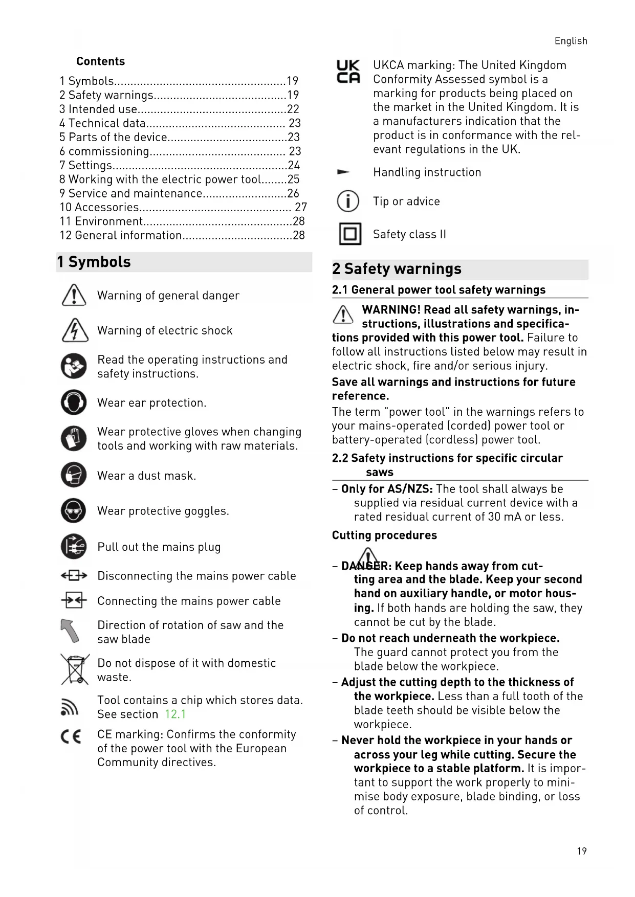
2.1 General power tool safety warnings
WARNING! Read all safety warnings, in structions, illustrations and specifica tions provided with this power tool. Failure to follow all instructions listed below may result in electric shock, fire and/or serious injury. Save all warnings and instructions for future reference. The term "power tool" in the warnings refers to your mains-operated (corded) power tool or battery-operated (cordless) power tool.
2.2 Safety instructions for specific circular
saws – Only for AS/NZS: The tool shall always be supplied via residual current device with a rated residual current of 30 mA or less. Cutting procedures – DANGER: Keep hands away from cut ting area and the blade. Keep your second hand on auxiliary handle, or motor hous ing. If both hands are holding the saw, they cannot be cut by the blade. – Do not reach underneath the workpiece. The guard cannot protect you from the blade below the workpiece. – Adjust the cutting depth to the thickness of the workpiece. Less than a full tooth of the blade teeth should be visible below the workpiece. – Never hold the workpiece in your hands or across your leg while cutting. Secure the workpiece to a stable platform. It is impor tant to support the work properly to mini mise body exposure, blade binding, or loss of control. English 19– Hold the power tool by the insulated han dle surfaces if you intend to perform work that entails a risk of cutting into hidden power cables or the tool's own power ca ble. Contact with live cables transfers an electric current to metal components on the electric power tool and causes electric shocks. – When ripping, always use a rip fence or straight edge guide. This improves the ac curacy of cut and reduces the chance of blade binding. – Always use blades with correct size and shape (diamond versus round) of arbour holes. Blades that do not match the mount ing hardware of the saw will run off-centre, causing loss of control. – Never use damaged or incorrect blade washers or bolt. The blade washers and bolt were specially designed for your saw, for optimum performance and safety of op eration. Kickback causes and related warnings – kickback is a sudden reaction to a pinched, jammed or misaligned saw blade, causing an uncontrolled saw to lift up and out of the workpiece toward the operator; – when the blade is pinched or jammed tight ly by the kerf closing down, the blade stalls and the motor reaction drives the unit rap idly back toward the operator; – if the blade becomes twisted or misaligned in the cut, the teeth at the back edge of the blade can dig into the top surface of the wood causing the blade to climb out of the kerf and jump back toward the operator. Kickback is the result of saw misuse and/or in correct operating procedures or conditions and can be avoided by taking proper precautions as given below. – Maintain a firm grip with both hands on the saw and position your arms to resist kickback forces. Position your body to ei ther side of the blade, but not in line with the blade. Kickback could cause the saw to jump backwards, but kickback forces can be controlled by the operator, if proper pre cautions are taken. – When blade is binding, or when interrupt ing a cut for any reason, release the trig ger and hold the saw motionless in the material until the blade comes to a com plete stop. Never attempt to remove the saw from the work or pull the saw back ward while the blade is in motion or kick back may occur. Investigate and take cor rective actions to eliminate the cause of blade binding. – When restarting a saw in the workpiece, centre the saw blade in the kerf so that the saw teeth are not engaged into the material. If a saw blade binds, it may walk up or kickback from the workpiece as the saw is restarted. – Support large panels to minimise the risk of blade pinching and kickback. Large pan els tend to sag under their own weight. Supports must be placed under the panel on both sides, near the line of cut and near the edge of the panel. – Do not use dull or damaged blades. Un sharpened or improperly set blades pro duce narrow kerf causing excessive fric tion, blade binding and kickback. – Blade depth and bevel adjusting locking levers must be tight and secure before making the cut. If blade adjustment shifts while cutting, it may cause binding and kickback. – Use extra caution when sawing into exist ing walls or other blind areas. The pro truding blade may cut objects that can cause kickback. Guard function – Check the lower guard for proper closing before each use. Do not operate the saw if the lower guard does not move freely and close instantly. Never clamp or tie the lower guard into the open position. If the saw is accidentally dropped, the lower guard may be bent. Raise the lower guard with the retracting handle and make sure it moves freely and does not touch the blade or any other part, in all angles and depths of cut. – Check the operation and condition of the guard return spring. If the guard and the spring are not operating properly, they must be serviced before use. The guard may operate sluggishly due to damaged parts, gummy deposits, or a build-up of debris. – Assure that the base plate of the saw will not shift while performing a "plunge cut". Blade shifting sideways will cause binding and likely kick back. English 20– Always observe that the guard is covering the blade before placing the saw down on bench or floor. An unprotected, coasting blade will cause the saw to walk back wards, cutting whatever is in its path. Be aware of the time it takes for the blade to stop after the switch is released. Function of the guide wedge [5-4] – Use the correct saw blade for the guide wedge. To ensure that the guide wedge functions properly, make sure that the blade core of the saw blade is thinner than the guide wedge and that the tooth width is greater than the thickness of the guide wedge. – Do not operate the saw if the guide wedge is bent. Even the slightest problem can cause the guard to close more slowly.
2.3 Safety instructions for the pre-
assembled saw blade Usage – The maximum speed specified on the saw blade must not be exceeded and the speed range must be adhered to. – The pre-installed saw blade is only de signed for use in circular saws. – Proceed with extreme care when unpack ing, packing and handling the tool (e.g. in stalling it in the machine). There is a risk of injury from extremely sharp cutting edges! – When handling the tool, wearing safety gloves provides a more secure hold of the tool and further reduces the risk of injury. – Circular saw blades with cracked bodies must be replaced. Repair is not permitted. – Circular saw blades with a combination de sign (soldered saw teeth) with saw tooth thickness smaller than 1 mm must no lon ger be used. – WARNING! Do not use tools with visible cracks or blunt or damaged cutting edges. Installation and mounting – Tools must be clamped in such a way that they cannot come loose during operation. – When assembling the tools, it must be en sured that the clamping takes place on the tool hub or the clamping surface of the tool, and that the cutting edges do not come into contact with other components. – Do not lengthen the key or tighten by hitting with a hammer. – The clamping surfaces must be cleaned to remove contamination, grease, oil and wa ter. – Clamping screws must be tightened ac cording to the manufacturer's instructions. – Only securely installed rings, e.g. rings that have been pressed in or those that are held in position by an adhesive bond, may be used to adjust the hole diameter of circular saw blades to the spindle diameter of the machine. The use of loose rings is not per mitted. Service and maintenance – Repairs and sanding work may only be car ried out by Festool customer service work shops or experts. – The tool design must not be changed. – Deresinify and clean the tool regularly (cleaning agent with pH between 4.5 and 8). – Blunt edges can be resharpened on the clamping surface to a minimum cutting edge thickness of 1 mm. – Only transport the tool in suitable packag ing – risk of injury!
2.4 Further safety instructions
Wear suitable personal protective equip ment: Ear protection, protective goggles, dust mask for work that generates dust, protective gloves for working with rough materials and for changing tools. – Harmful/toxic dust may be produced dur ing your work (e.g. paint containing lead, certain types of wood or metals). Contact with or inhalation of this dust may pose a risk for the operating personnel or persons in the vicinity. Comply with the safety regu lations that apply in your country. – Wear a P2 respiratory mask to protect your health. In enclosed spaces, ensure that there is sufficient ventilation and con nect a mobile dust extractor. – This power tool cannot be installed in a work bench. The power tool may become unsafe and cause serious accidents if in stalled in benches from other manufactur ers or self-manufactured work benches. – Check whether there are any signs of dam age to the housing components, such as cracks or stress whitening. Have any dam English 21aged components repaired before using the power tool. – Use appropriate detection devices to look for any hidden supply lines or consult your local utility company. If the insertion tool makes contact with live cables, it can result in fire and electric shock. Damage to a gas pipe can lead to an explosion. Penetration of a water pipe can result in damage to property.
2.5 Sawing aluminium
When sawing aluminium, the following meas ures must be taken for safety reasons: – Wear protective goggles. – Regularly clean dust deposits from the mo tor housing on the power tool. – Use an aluminium saw blade. – Close the viewing window/chip guard. – Install an upstream residual-current circuit breaker (RCD, PRCD). – When sawing panels, they must be lubrica ted with petroleum, but thin-walled profiles (up to 3 mm) can be sawed without lubrica tion.
The levels determined in accordance with EN 62841 are typically: Sound pressure level L
= 90 dB(A) Sound power level L
= 101 dB(A) Uncertainty K = 3 dB CAUTION Noise generated when working Risk of damage to hearing ► Use ear protection. Vibration emission level a
(vector sum for three directions) and uncertainty K measured in accordance with EN 62841: Sawing wood
The specified emission levels (vibration, noise) – are used to compare machines. – They are also used for making preliminary estimates regarding vibration and noise load during operation. – They represent the primary applications of the power tool. CAUTION The emission values may deviate from the specified values. This is dependent on how the tool is used and the type of workpiece being machined. ► The actual load during the entire operating cycle must be evaluated. ► Depending on the actual load, suitable pro tective measures must be defined in order to protect the operator. 3 Intended use Circular saws are designed for sawing wood, materials similar to wood, gypsum and cement- bonded fibre materials and plastics. When fitted with the special saw blades for aluminium that are offered by Festool, these machines can also be used for sawing aluminium. Materials containing asbestos must NOT be processed. Do not use cutting or abrasive wheels. This power tool may only be used by experts or instructed persons. The user is liable for improper or non-in tended use.
Only use saw blades with the following dimen sions: – Saw blades according to EN 847-1 – Saw blade diameter 160 mm – Cutting width 1.8 mm – Locating bore 20 mm – Standard blade thickness 1.1 – 1.4 mm – Suitable for speeds of up to 9500 rpm Festool saw blades comply with EN 847-1. Only saw materials for which the saw blade in question has been designed. English 224 Technical data Plunge-cut saw TS 55 FEBQ, TS 55 FEQ TS 55 FQ Power 1200 W 1050 W Speed (no-load) 2000 – 5800 rpm 6500 rpm Inclination -1° to 47° -1° to 47° Cutting depth at 0° 0 – 55 mm 0 – 55 mm Cutting depth at 45° 0 – 43 mm 0 – 43 mm Saw blade dimensions 160 x 1.8 x 20 mm 160 x 1.8 x 20 mm Weight as per EPTA procedure 01:2014 (without pow er cable)
5 Parts of the device [1-1] Adjustable jaws [1-2] Scale [1-3] Rotary knobs for adjusting the angle [1-4] Handles [1-5] Lever for changing the tool [1-6] Safety lock [1-7] On/off switch [1-8] Extractor connector [1-9] Unlocking devices for undercuts -1° to 47° [1-10] Speed control (not on the TS 55 FQ) [1-11] Mains power cable [1-12] Split scale for the cutting depth stop (with/without a guide rail) [1-13] Cutting depth adjusting screw for re conditioned saw blades [1-14] Cutting depth stop [1-15] Gauge marker [1-16] Viewing window/chip guard [1-17] Splinter guard [1-18] Protective lid The specified illustrations appear at the begin ning of the Operating Instructions. Accessories shown or described are not always included in the scope of delivery. 6 commissioning WARNING Unauthorised voltage or frequency. Risk of accidents ► The mains voltage and the frequency of the power source must correspond to the specifications on the name plate. ► In North America, only Festool machines with the voltage specifications 120 V/60 Hz may be used. CAUTION Heating of the Plug it connection if bayonet fitting is not completely locked Risk of burns ► Before switching on the power tool, make sure that the bayonet fitting at the mains cable is closed fully and locked. Always switch off the machine before connecting and disconnecting the mains power cable. Connecting and detaching the mains power ca ble [1-11] see figure [2]. Slide the safety lock [1-6] upwards and press the on/off switch [1-7] (press = ON/release = OFF). Pressing the safety lock unlocks the plunging mechanism. The saw unit can then be moved downwards. This causes the saw blade to emerge from the guard. English 237 Settings WARNING Risk of injury, electric shock ► Always disconnect the mains plug from the socket before performing any work on the machine.
The machines TS 55 FEBQ, TS 55 FEQ come with full-wave electronics with the following properties: Smooth start-up The electronically controlled smooth start-up function ensures that the power tool starts up smoothly. Constant speed The motor speed is electronically kept con stant. This ensures a uniform cutting speed even when under load. Speed control You can continuously adjust the speed within the speed range using the adjusting wheel [1-10] (see "Technical data"). This ena bles you to optimise the cutting speed to suit each surface. Speed range per material Solid wood (hard, soft) 6 Chipboard and hardboard 3–6 Laminated wood, blockboard, veneered and laminated panels
Laminate, mineral materials 4–6 Plaster- and cement-bonded chipboard and fibreboard 1–3 Aluminium panels and profiles up to 15 mm 4–6 Plastics, fibre-reinforced plastics, paper and fabric 3–5 Acrylic glass 4–5 Current limiting Current limiting prevents excessive current consumption under extreme overload, which can lead to a decrease in the motor speed. The motor immediately restarts after the load is re moved. Brake The saw TS 55 FEBQ comes with an electronic brake. The saw blade is stopped electronically within approximately two seconds of switching off the machine. Temperature cut-out The power supply is restricted and the speed reduced if the motor exceeds a certain temper ature. The power tool continues operating at re duced power to allow the ventilator to cool the motor quickly. The power tool starts up again automatically once the motor has cooled suffi ciently.
7.2 Adjusting the cutting depth
The cutting depth can be set at 0 – 55 mm at the cutting depth stop [3-1]. The saw unit can now be pushed downwards as far as the cutting depth that is set. Cutting depth without guide rail max. 55 mm +FS Cutting depth with FS guide rail max. 51 mm
7.3 Setting the cutting angle
between 0° and 45°: ► Unscrew the rotary knobs [4-1]. ► Swivel the saw unit to the desired cutting angle [4-2]. ► Tighten the rotary knobs [4-1]. Both positions (0° and 45°) are set at the factory and can be readjusted by the cus tomer service team. When making angled cuts, slide the view ing window/splinter guard to the highest position. To undercut -1° and 47°: ► Swivel the saw unit to the end position (0°/ 45°) as described above. ► Pull out the release button [4-3] slightly. ► For -1° undercuts, also pull the release button [4-4]. The saw unit engages in the -1°/47° position. ► Tighten the rotary knobs [4-1].
7.4 Selecting the saw blade
Festool saw blades are identified by a coloured ring. The colour of the ring represents the ma terial for which the saw blade is suited. Refer to the necessary saw blade data (see sec tion 3.1). English 24Colour Material Symbol Yellow Wood Red Laminate, mineral ma terial HPL/TRESPA
Green Plaster- and cement- bonded chipboard and fibreboard Blue Aluminium, plastic "$3:-
7.5 Changing the saw blade
WARNING Risk of injury, electric shock ► Always disconnect the mains plug from the socket before performing any work on the machine. CAUTION Risk of injury from hot and sharp insertion tool ► Do not use any blunt or faulty insertion tools. ► Wear protective gloves when handling an insertion tool. Remove the saw blade ► Swivel the machine to 0° before replacing the saw blade and adjust the maximum cut ting depth. ► Turn the lever [5-2] as far as it will go. ► Slide the safety lock [5-1] upwards and push the saw unit downwards until it clicks into place. ► Loosen the screw [5-5] using the Allen key [5-3]. ► Remove the saw blade [5-7]. Inserting the saw blade WARNING! Check the screws and flange for contamination and only use clean and undam aged parts. ► Insert the new saw blade. WARNING! The direction of rotation of the saw blade [5-8] and saw [5-6] must match. Serious injuries may occur in the event of non-compliance. ► Insert the outer flange [5-9] so that the pin engages in the recess on the inner flange. ► Tighten the screw [5-5]. ► Reposition the lever [5-2].
7.6 Fitting the viewing window/splinter
guard The viewing window (transparent) [6-1] pro vides a view of the saw blade and optimises dust extraction. With 0° cuts, the splinter guard (green) [6-2] also improves the quality of the cutting edge of the sawn-off workpiece on the upper side. ► Insert the splinter guard [6-2]. ► Screw the rotary knob [6-3] through the long hole in the splinter guard. ► Make sure that the nut [6-4] is seated se curely in the splinter guard. ► CAUTION! Only use the rotary knob sup plied with your plunge-cut saw. The rotary knob of another saw may be too long and jam the saw blade. Sawing a splinter guard You must bed in the splinter guard before using it: ► Set the machine to maximum cutting depth. ► Set the machine speed to 6. ► Place the machine for sawing the splinter guard on a test piece of wood.
WARNING Heath hazard posed by dust ► Always work with an extractor. ► Comply with national regulations. Festool mobile dust extractor A Festool mobile dust extractor with a suction hose diameter of 27/32 mm or 36 mm (36 mm recommended due to the reduced risk of clog ging) can be connected to the extractor connec tor . The adapter on a 27 diameter suction hose is inserted into the angle adapter . The adapter on a 36 diameter suction hose is inserted over the angle adapter . CAUTION! A static charge may build up if no antistatic suction hose is used. The user may receive an electric shock and the power tool's electronics may be damaged. 8 Working with the electric power tool When working on the machine, observe all of the safety warnings that are listed at the start as well as the following rules: English 25Before starting – Before each use, check whether the drive unit with the saw blade correctly and fully swivels back up into its initial position in the protective housing. Do not use the saw if the upper end position is not secured. Never clamp or secure the swivelling drive unit at a specific cutting depth. This would mean that the saw blade is not protected. – Check the plunging mechanism prior to use and do not use the machine if it does not work correctly. – Check that the saw blade is securely in place. – Make sure that the rotary knob [1-3] is tightened before starting work. – Make sure that extractor hose and mains power cable do not snag the entire saw cut, either on the workpiece, the workpiece support or hazards on the ground. – Always secure the workpiece in such a way that it cannot move during machining. – Position the workpiece so that it is stress- free and level. During work – When working, always hold the power tool with both hands on the handles [1-4]. This is a prerequisite for precise work and is es sential for plunge-cutting. Plunge into the workpiece slowly and evenly. – Only guide the power tool towards the workpiece when it is switched on. – Always push the saw forwards [9-2], and never towards yourself. – Adapt the infeed speed to prevent the cut ters on the saw blade from overheating and prevent plastic materials from melting dur ing cutting. The harder the material to be sawn, the lower the feed speed needs to be. – Do not work with the machine if the elec tronics are defective, because this may lead to excessive speeds. You can tell if the electronics are defective if there is no smooth start-up or if it is not possible to regulate the speed or where smoke is present or if there is a smell of burning coming from the machine. – Make sure that the guard completely sur rounds the saw blade before placing the saw on the worktop or on the ground.
8.1 Sawing along the scribe mark
The gauge marker [7-2] displays the cutting line for 0° and 45° cuts (without a guide rail).
8.2 Cutting sections
Position the machine with the front part of the saw table on the workpiece, switch on the ma chine, push it down to the set cutting depth and push it forward in the cutting direction.
8.3 Sawing cut-outs (plunge cuts)
In order to avoid kickbacks, the following instructions must always be followed when plunge cutting: – Always position the machine with the rear edge of the saw table against a fixed stop. – When working with the guide rail, position the machine at the FS-RSP kickback stop (accessory) [9-4], which is clamped to the guide rail. Procedure ► Place the machine on the workpiece and position it at a stop (kickback stop). ► Switch on the machine. ► Slowly push the machine down to the set cutting depth and push it forward in the cut ting direction. The marks [7-1] indicate the absolute front and rear cutting points of the saw blade (Ø 160 mm) when using the saw at maximum cutting depth with the guide rail.
8.4 Gypsum and cement-bound fibreboards
Due to the high volume of dust, it is recommen ded to use the cover ABSA-TS55/60 (accesso ries) which can be mounted at the side at the protective cover and a Festool mobile dust ex tractor. 9 Service and maintenance WARNING Risk of injury, electric shock ► Always pull the mains plug from the socket before performing any servicing and main tenance work. ► All maintenance and repair work which re quires the housing to be opened should al ways be carried out by an authorised serv ice workshop. Customer service and repairs must only be carried out by the manufac turer or service workshops. Find the nearest address at: www.festool.co.uk/service English 26Always use original Festool spare parts. Order no. at: www.festool.co.uk/service EKAT
The tool is equipped with special self-discon necting carbon brushes. If they wear out, the power supply is disconnected automatically and the tool stops. Observe the following instructions: ► Damaged safety devices and parts, such as a faulty lever for changing tools [1-5], must be properly repaired or replaced in a recog nised specialist workshop, unless otherwise indicated in the operating manual. ► Check the condition and fault-free function ing of the recuperating springs, which push the entire drive mechanism bearing into the upper protected end positions. ► To ensure constant air circulation, always keep the cooling air openings in the housing clean and free of blockages. ► Use an extractor on all openings in order to remove wood chips and splinters from the power tool. Never open the protective lid [1-18]. ► When working with plaster- and cement- bonded fibreboards, clean the tool particu larly thoroughly. Clean the vents of the power tool and on/off switch using dry, oil- free compressed air. Otherwise, gypsum dust deposits may build up inside the power tool's housing and on the on/off switch and harden when exposed to humidity. This may impair the switching mechanism
9.1 Reconditioned saw blades
You can use the adjusting screw [8-1] to pre cisely set the cutting depth for reconditioned saw blades. ► Set the cutting depth stop [8-2] to 0 mm (with guide rail). ► Unlock the saw unit and push it downwards as far as the stop. ► Screw the adjusting screw [8-1] in until the saw blade comes into contact with the workpiece.
9.2 Saw table wobbles
The saw table must be on an even surface when adjusting the cutting angle. If the saw table wobbles, the setting must be implemented again (Section 7.3). 10 Accessories Always use accessories and consumable mate rials approved by Festool. See Festool cata logue or www.festool.com. The power tool may become unsafe and lead to serious accidents if other accessories and con sumables are used. In addition to the accessories described, Festool also provides a comprehensive range of system accessories that allow you to use your machine more effectively and in diverse appli cations, e.g.:
- Parallel stop, table widener PA-TS 55
- Side-mounted cover, false joint ABSA-TS
- Kickback stop FS-RSP
- Parallel stop FS-PA and guide extension FS-PA-VL
- Multifunction table MFT/3
10.1 Saw blades, other accessories
In order to saw different materials quickly and cleanly, Festool offers saw blades for all appli cations and these are specially designed for your Festool saw.
The guide rail enables you to make clean, accu rate cuts while simultaneously protecting the surface of the workpiece from damage. In conjunction with the extensive range of ac cessories, exact angled cuts, mitre cuts and fit ting work can be completed with the guide sys tem. The option of attaching the guide rail se curely using clamps [9-5] ensures safer work ing conditions. ► Adjust the guide play between the saw table and the guide rail using the two adjustable jaws [9-1]. Bed in the splinter guard [9-3] before using the guide rail for the first time: ► Set the machine speed to 6. ► Place the machine at the rear end of the guide rail together with the complete guide plate. ► Switch on the machine. ► Push down the machine slowly to the max. preset cutting depth and cut along the full length of the splinter guard without stop ping. The edge of the splinter guard now corresponds exactly to the cutting edge. Position the guide rail for sawing the splinter guard on a test piece of wood. English 2711 Environment Do not dispose of the device in the household waste! Recycle devices, ac cessories and packaging. Observe appli cable national regulations. EU only: In accordance with the European Di rective on waste electrical and electronic equipment and implementation in national law, used power tools must be collected separately and handed in for environmentally friendly re cycling. Information on REACH: www.festool.com/reach 12 General information Imported into the UK by Festool UK Ltd 1 Anglo Saxon Way Bury St Edmunds IP30 9XH Great Britain