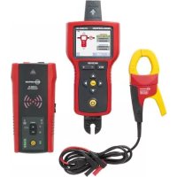
AT8030EUR - Electric detector Beha-Amprobe - Free user manual and instructions
Find the device manual for free AT8030EUR Beha-Amprobe in PDF.




| Product type | Advanced cable tracer kit |
| Brand | Beha-Amprobe |
| Model | AT8030EUR |
| Kit components | AT-8000-RE receiver, AT-8000-TE transmitter, CT-400-EUR signal clamp, TL-8000-EUR test lead kit, battery chargers, rechargeable NiMH batteries, plug adapter, magnetic hanger, carrying case |
| Measurement category | CAT IV 600 V (receiver and transmitter), CAT II 1000 V (test probes) |
| Operating voltage | 0 to 600 V AC/DC |
| Operating frequencies | Live: 6.25 kHz; Dead: 32.768 kHz; Loop mode: 6.25 kHz |
| Detection range (Smart Sensor) | Locating: ~5 cm radius; Direction indication: up to 1.5 m |
| Detection range (Live Tip Sensor) | Locating: ~5 cm; Detection: up to 6.7 m |
| Detection range (Dead Tip Sensor) | Detection: up to 4.3 m |
| NCV detection range | Locating: ~5 cm; Detection: up to 1.2 m (90-600 V AC, 40-400 Hz) |
| Display (receiver) | 3.5-inch color TFT LCD display, 320x240 resolution |
| Power supply | Receiver: 4 AA batteries (alkaline or NiMH); Transmitter: 8 AA batteries (alkaline or NiMH); Clamp: Passive |
| Battery life (receiver) | Approximately 9 hours |
| Battery life (transmitter) | High/Low mode: ~25 h; Loop mode: ~18 h |
| Dimensions (receiver) | 278 x 113 x 65 mm |
| Dimensions (transmitter) | 183 x 93 x 50 mm |
| Dimensions (clamp) | 150 x 70 x 30 mm |
| Weight (receiver with batteries) | ~0.544 kg |
| Weight (transmitter with batteries) | ~0.57 kg |
| Weight (clamp) | ~0.114 kg |
| Protection rating | Receiver: IP52; Transmitter and clamp: IP40 |
| Fuse (transmitter) | 1.6 A, 700 V, fast-acting, ∅ 6x32 mm |
| Warranty | 2 years (except disposable batteries and accidental damage) |
| Operating temperature | -20 °C to 50 °C (receiver and transmitter); 0 °C to 50 °C (clamp) |
| Safety standards | UL/IEC/EN 61010-1, CAT IV 600 V, double insulation |
Frequently Asked Questions - AT8030EUR Beha-Amprobe
User questions about AT8030EUR Beha-Amprobe
0 question about this device. Answer the ones you know or ask your own.
Ask a new question about this device
Download the instructions for your Electric detector in PDF format for free! Find your manual AT8030EUR - Beha-Amprobe and take your electronic device back in hand. On this page are published all the documents necessary for the use of your device. AT8030EUR by Beha-Amprobe.
USER MANUAL AT8030EUR Beha-Amprobe
AT-8000-EUR Advanced Wire Tracers
Limited Warranty and Limitation of Liability
Your Beha-Amprobe product will be free from defects in material and workmanship for two years from the date of purchase unless local laws require otherwise. This warranty does not cover fuses, disposable batteries or damage from accident, neglect, misuse, alteration, contamination, or abnormal conditions of operation or handling. Resellers are not authorized to extend any other warranty on the behalf of Beha-Amprobe. To obtain service during the warranty period, return the product with proof of purchase to an authorized Beha-Amprobe Service Center or to an Beha-Amprobe dealer or distributor. See Repair Section for details. THIS WARRANTY IS YOUR ONLY REMEDY. ALL OTHER WARRANTIES - WHETHER EXPRESS, IMPLIED OR STATUTORY - INCLUDING IMPLIED WARRANTIES OF FITNESS FOR A PARTICULAR PURPOSE OR MERCHANTABILITY, ARE HEREBY DISCLAIMED. MANUFACTURER SHALL NOT BE LIABLE FOR ANY SPECIAL, INDIRECT, INCIDENTAL OR CONSEQUENTIAL DAMAGES OR LOSSES, ARISING FROM ANY CAUSE OR THEORY. Since some states or countries do not allow the exclusion or limitation of an implied warranty or of incidental or consequential damages, this limitation of liability may not apply to you.
Repair
All Beha-Amprobe tools returned for warranty or non-warranty repair or for calibration should be accompanied by the following: your name, company's name, address, telephone number, and proof of purchase. Additionally, please include a brief description of the problem or the service requested and include the test leads with the product. Non-warranty repair or replacement charges should be remitted in the form of a check, a money order, credit card with expiration date, or a purchase order made payable to Beha-Amprobe.
In-warranty Repairs and Replacement – All Countries
Please read the warranty statement and check your battery before requesting repair. During the warranty period, any defective test tool can be returned to your Beha-Amprobe distributor for an exchange for the same or like product. Please check the "Where to Buy" section on beha-amprobe.com for a list of distributors near you. Additionally, in the United States and Canada, in-warranty repair and replacement units can also be sent to an Beha-Amprobe Service Center (see address below).
Non-warranty Repairs and Replacement – Europe
European non-warranty units can be replaced by your Beha-Amprobe distributor for a nominal charge. Please check the "Where to Buy" section on beha-amprobe.com for a list of distributors near you.
Beha-Amprobe
Division and reg. trademark of Fluke Corp. (USA)
Germany*
In den Engematten 14
79286 Glottertal
Germany
Phone: +49 (0) 7684 8009 - 0
beha-amprobe.de
United Kingdom
52 Hurricane Way
Norwich, Norfolk
NR6 6JB United Kingdom
Phone: +44 (0) 1603 25 6662
beha-amprobe.com
The Netherlands - Headquarters**
Science Park Eindhoven 5110
5692 EC Son
The Netherlands
Phone: +31 (0) 40 267 51 00
beha-amprobe.com
*(Correspondence only – no repair or replacement available from this address. European customers please contact your distributor.)
**single contact address in EEA Fluke Europe BV
CONTENTS
1. PRECAUTIONS AND SAFETY MEASURES ...... 2
2. KIT COMPONENTS....5
2.1 AT-8000-RE Receiver 6
2.2 AT-8000-TE Transmitter 8
2.3 CT-400-EUR Signal Clamp 11
3. MAIN APPLICATIONS.... 12
3.1 Tracing Energized Wires....13
• 3.1 a Using the Receiver in Energized SMART SENSOR™ mode....14
• 3.1 b Using Receiver in Energized Tip Sensor mode....15
3.2 Tracing De-Energized Wires....16
• Using Receiver in De-Energized Tip Sensor mode
3.3 Identifying Breakers and Fuses....17
- Using Receiver in Energized & De-Energized Breaker mode
3.4 Non-Contact Voltage Mode (NCV) 20
4. SPECIAL APPLICATIONS ...... 21
4.1 RCD-Protected Circuit Wire Tracing....21
4.2 Finding Breaks/Opens 22
4.3 Finding Shorts 22
4.4 Tracing Wires in Metal Conduit 23
4.5 Tracing Non-Metallic Pipes and Conduits 23
4.6 Tracing Shielded Wires 24
4.7 Tracing Underground Wires....25
4.8 Tracing Low Voltage Wires and Data Cables 25
4.9 Sorting Bundled Wires 26
4.10 Mapping a Circuit using Test Leads Connection....27
4.11 Tracing Breakers/Fuses on Systems with Light Dimmers 27
4.12 Signal Clamp - Closed Loop Circuits 28
4.13 Signal Clamp - Mapping Circuits....30
5. MAINTENANCE....31
5.1 Battery Replacement....31
5.2 Fuse Replacement....34
6. SPECIFICATIONS.... 35
General
For your own safety and to avoid damage to the instrument we suggest you to follow the procedures listed below:
NOTE: Before and during measurements be diligent to follow the instructions.
- Make sure that the electrical instrument is operating properly before use.
- Before attaching any of the conductors, make sure that the voltage present in the conductor is in the range of the instrument.
- Keep the instruments in their carrying case when not in use.
- If the Transmitter or Receiver will not be used for a long time, remove the batteries to prevent leakage in the instruments.
- Use Beha-Amprobe approved cables and accessories only.
Safety precautions
In many instances, dangerous levels of voltage and/or current may be present. Therefore, it is important to avoid direct contact with any uninsulated voltage/current carrying surfaces. Insulated gloves and protective clothing should be worn in hazardous voltage areas.
- Do not measure voltage or current in wet, damp or dusty places.
- Do not measure voltage in the presence of gas, explosive materials or combustibles.
- Do not touch the circuit under test if no measurement is being taken.
- Do not touch exposed metal parts, such as unused terminals and circuits.
- Do not use the instrument if it appears to be malfunctioning (i.e. if you notice deformations, breaks, leakage of substances, absence of messages on the display, etc).
Safety information
The product complies with:
- UL/IEC/EN 61010-1, CAN/CSA C22.2 No. 61010-1, Pollution Degree 2, Measurement category IV 600 V MAX
• IEC/EN 61010-2-030
• IEC/EN 61010-2-032
• IEC/EN 61010-031 (test leads)
• EMC IEC/EN 61326-1
Measurement Category IV (CAT IV) is for circuits that are directly connected to the primary utility power source for a given building or between the building power supply and the main distribution board. Such equipment may include electricity tariff meters and primary over current protection devices.
CENELEC Directives
The instruments conform to CENELEC Low-voltage directive 2014/35/EU and Electromagnetic compatibility directive 2014/30/EU.
⚠️⚠️Warnings: Read Before Using
To avoid the possibility of electric shock or personal injury:
- Use the Product only as specified in this manual or the protection provided by the instrument may be compromised.
- Avoid working alone so assistance can be rendered.
- Test on a known signal source within the rated voltage range of the Product both before and after use to ensure the Product is in good working conditions.
- Do not use the Product around explosive gas, vapor, or in damp or wet environments.
- Inspect the Product before use and do not use if it appears damaged. Check for cracks or missing plastic. Pay particular attention to the insulation around the connectors.
- Inspect the test leads before use. Do not use if insulation is damaged or metal is exposed.
- Do not use the Product if it operates incorrectly. Protection may be impaired. When in doubt, have the Product serviced.
- Check the test leads for continuity. Replace damaged test leads before using the Product.
- Have the Product serviced only by qualified service personnel.
- Use extreme caution when working around bare conductors or bus bars. Contact with the conductor could result in electric shock.
- Do not hold the Product beyond the tactile barrier.
- Do not apply more than the rated voltage and CAT rating, as marked on the Product, between the terminals or between any terminal and earth ground.
- Remove test leads from the Product before opening the Product case or battery cover.
- Never operate the Product with the battery cover removed or the case open.
- Use caution when working with voltages above 30 V AC RMS, 42 V AC peak, or 60 V DC. These voltages pose a shock hazard.
- Do not attempt to connect to any circuit carrying voltage that may exceed the maximum range of the Product.
- Use the proper terminals, functions and ranges for your measurements.
- When using alligator clips and test probes, keep fingers behind the finger guards.
- Use only exact fuse replacement and specified replacement parts.
- When making electrical connections, connect the common test lead before connecting the live test lead; when disconnecting, disconnect the live test lead before disconnecting the common test lead.
- To avoid false readings that can lead to electrical shock and/or injury, replace the batteries as soon as the low battery indicator appears. Check Product operation on a known source before and after use.
- Use only AA batteries, properly installed in the Product case, to power the Product (see Section 5.1: Battery Replacement).
- When servicing, use only specified user serviceable replacement parts.
- Adhere to local and national safety codes. Individual protective equipment must be used to prevent shock and arc blast injury where hazardous live conductors are exposed.
- Only use the test lead provided with the Product or UL Listed Probe Assembly rated CAT IV 600 V or better.
- Do not use the HOT STICK (TIC 410A) to operate the AT-8000-RE Receiver at voltages above 600 V.
- Remove the batteries if the Product is not used for an extended period of time, or if stored in temperatures above 50 °C (122 °F). If the batteries are not removed, battery leakage can damage the Product.
- Follow all battery care and charging instructions from the battery manufacturer.
- Do not use the Product to check for absence of voltage. Please use a voltage tester instead.
Symbols used in this product
 | Battery status – Displays the remaining battery charge. |
 | Home – Return to home screen when selected. |
| S4401 | Help – Enters to the help guide when selected. |
| S4402 | Settings – Enters to the settings menu when selected. |
| S4403 | Indicates the volume is muted. |
| 07301 | Volume – Displays the volume in four levels. |
| S4404 | Sensitivity indicator – Displays the sensitivity level from 1 to 10. |
| [000KZ] | Icon indicating energized system. |
| S4405 | Icon indicating de-energized system. |
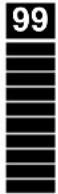 | Signal strength indicator – Shows the strength of the signal from 0 to 99. |
| SIGNAL | |
| MAN/AUTO | Shows whether the sensitivity adjustment is in Manual or Automatic mode. |
 | Lock indicates if the Auto sensitivity lock is active (Only in Auto sensitivity mode). |
| S4406 | Application and removal from hazardous live conductors permitted. |
| S4407 | Caution! Risk of electric shock. |
| S44071 | Caution! Refer to the explanation in this Manual. |
| S44072 | The equipment is protected by double insulation or reinforced insulation. |
| S44073 | Earth (Ground). |
| CAT IV 600V | Overvoltage up to Category IV 600V (transient protection up to 8 kV). |
 | Fuse. |
| S4408 | Conforms to relevant North American Safety Standards. |
| S4409 | Complies with European Directives. |
| S44091 | Conforms to relevant Australian standards. |
| [S2W7] | This product complies with the WEEE Directive marking requirements. The affixed label indicates that you must not discard this electrical/electronic product in domestic household waste. Product Category: With reference to the equipment types in the WEEE Directive Annex I, this product is classed as category 9 “Monitoring and Control Instrumentation” product. Do not dispose of this product as unsorted municipal waste. |
This manual contains information and warnings that must be followed for safe operation and maintenance of the instrument. If the Product is used in a manner not specified by the manufacturer, the protection provided by the Product may be impaired. This Product meets water and dust protection IP52 (Receiver) and IP40 (Transmitter and signal clamp) per IEC 60529. Do NOT operate outside during periods of rainfall. The Product is double insulated for protection per EN 61010-1 to CAT IV 600 V.
CAUTION: Do not connect the Transmitter to a separate ground in Electrically Susceptible Patient areas of a health care facility. Make the ground connection first and disconnect it last.
2. KIT COMPONENTS
Your shipping box should include:
| AT-8020-EUR KIT | AT-8030-EUR KIT | |
| AT-8000-RE RECEIVER | 1 | 1 |
| AT-8000-TE TRANSMITTER | 1 | 1 |
| TL-8000-EUR TEST LEAD AND ACCESSORY KIT* | 1 | 1 |
| CC-8000-EUR HARD CARRYING CASE | 1 | 1 |
| BATTERY CHARGERS | - | 3 |
| RECHARGEABLE BATTERIES NIMH TYPE 1.2 V AA (IEC LR6) | - | 12 |
| BATTERIES ALKALINE 1.5 V AA (IEC LR6) | 12 | - |
| CT-400-EUR SIGNAL CLAMP | - | 1 |
| ADPTR-SCT-xx Socket adapter | 1 | 1 |
| HS-1 MAGNETIC HANGER | - | 1 |
| USER MANUAL | 1 | 1 |
| QUICK START GUIDE | 1 | 1 |
\*TL-8000-EUR test lead and accessory kit includes:
- 2 x 1 m test leads (red, black): CAT IV 600 V
• 1 x 7 m test lead (green): CAT IV 600 V - 2 x alligator clips (red, black): CAT IV 600 V
• 2 test probes (red, black): CAT II 1000 V
Optional Accessories:
• TL-8000-25M TEST LEAD LONG 25m green
2.1 AT-8000-RE Receiver
The AT-8000-RE Receiver detects the signal generated by the AT-8000-TE Transmitter along wires using either the TIP SENSOR or SMART SENSOR^TM and displays this information on the full color TFT LCD display.
Active tracing using a signal generated by the AT-8000-TE Transmitter
The SMART SENSOR™ works with a 6 kHz signal generated along Energized wires (above 30 V AC/DC) and provides an indication of the wire position and direction relative to the Receiver. The SMART SENSOR™ is not designed to work on De-energized systems; for that application the TIP SENSOR should be used in De-energized mode.
The TIP SENSOR may be used on either Energized or De-energized wires and can be used for general tracing, tracing in tight spaces, locating breakers/fuses, pinpointing wires in bundles or in junction boxes. The TIP SENSOR mode will pinpoint the wire location with both an audible and visual indication of detected signal strength, but unlike SMART SENSOR™ mode it will not provide wire direction or orientation.
Note: The Receiver will NOT detect signals from the wire through metal conduit or shielded cable. Refer to Special Applications, section 4.4 "Tracing Wires In Metal Conduit" for alternative tracing methods.

text_image
TIP SENSOR CAT IV 600 V AC TIP SENSOR SMART SENSOR™ (Back side) BEHA-AMPROBE AT-8000-RE ENERGIZED: SMART SENSOR TIP SENSOR BREAKERS DE-ENERGIZED: TIP SENSOR BREAKERS LCD DISPLAY Full color TFT display TACTILE BARRIER NCV BUTTON Non-Contact Voltage mode 4-WAY NAVIGATION KEYS RUBBER OVER MOLDED ENCLOSURE RECEIVER NCV - + SENSITIVITY ADJUSTMENT BUTTON (-/+) ENTER BUTTON Selects the function POWER BUTTON BATTERY COMPARTMENT (Back side) HOT STICK ATTACHMENT POINT (Do not use for voltage higher than 600 V)Figure 2.1a: Overview of AT-8000-RE Receiver
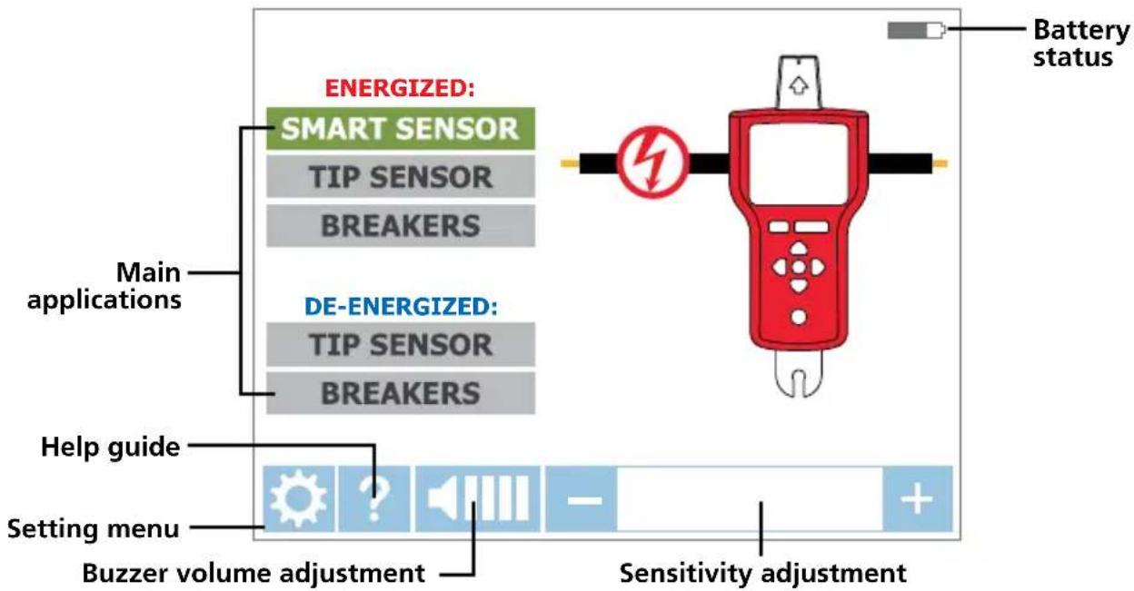
flowchart
graph TD
    A["Battery status"] --> B["Energy Level"]
    B --> C["Main applications"]
    B --> D["Energy Level"]
    D --> E["Energy Level"]
    E --> F["Energy Level"]
    F --> G["Energy Level"]
    G --> H["Energy Level"]
    H --> I["Energy Level"]
    I --> J["Energy Level"]
    J --> K["Energy Level"]
    K --> L["Energy Level"]
    L --> M["Energy Level"]
    M --> N["Energy Level"]
    N --> O["Energy Level"]
    O --> P["Energy Level"]
    P --> Q["Energy Level"]
    Q --> R["Energy Level"]
    R --> S["Energy Level"]
    S --> T["Energy Level"]
    T --> U["Energy Level"]
    U --> V["Energy Level"]
    V --> W["Energy Level"]
    W --> X["Energy Level"]
    X --> Y["Energy Level"]
    Y --> Z["Energy Level"]
    Z --> AA["Energy Level"]
    AA --> AB["Energy Level"]
    AB --> AC["Energy Level"]
    AC --> AD["Energy Level"]
    AD --> AE["Energy Level"]
    AE --> AF["Energy Level"]
    AF --> AG["Energy Level"]
    AG --> AH["Energy Level"]
    AH --> AI["Energy Level"]
    AI --> AJ["Energy Level"]
    AJ --> AK["Energy Level"]
    AK --> AL["Energy Level"]
    AL --> AM["Energy Level"]
    AM --> AN["Energy Level"]
    AN --> AO["Energy Level"]
    AO --> AP["Energy Level"]
    AP --> AQ["Energy Level"]
    AQ --> AR["Energy Level"]
    AR --> AS["Energy Level"]
    AS --> AT["Energy Level"]
    AT --> AU["Energy Level"]
    AU --> AV["Energy Level"]
    AV --> AW["Energy Level"]
    AW --> AX["Energy Level"]
    AX --> AY["Energy Level"]
Figure 2.1b: Overview of home screen elements
text_image
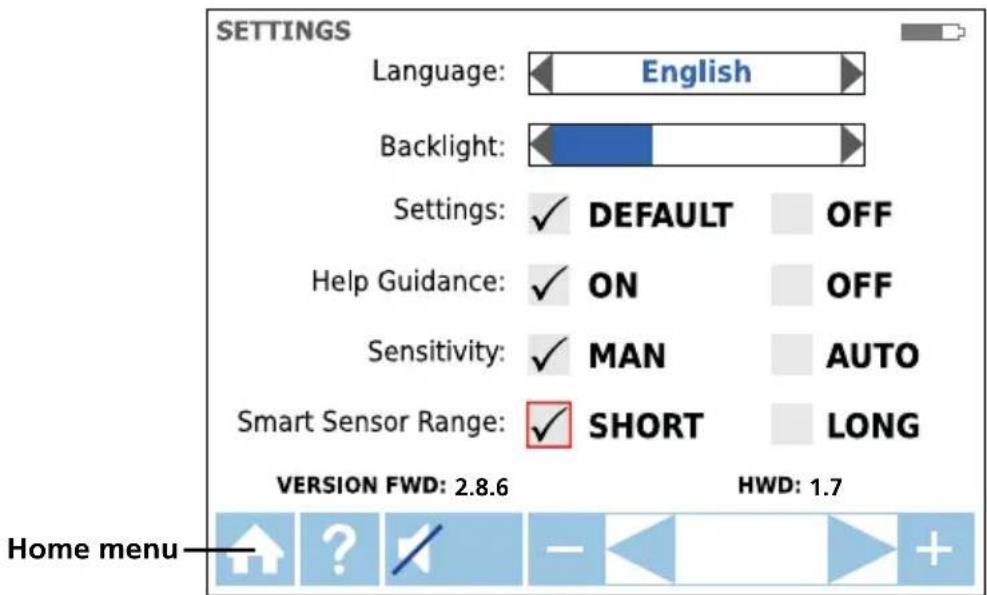
SETTINGS Language: English Backlight: Settings: ✓ DEFAULT OFF Help Guidance: ✓ ON OFF Sensitivity: ✓ MAN AUTO Smart Sensor Range: ✓ SHORT LONG VERSION FWD: 2.8.6 HWD: 1.7 Home menuFigure 2.1c: Overview of settings menu elements
| Language | Select desired language |
| Backlight | 25%, 50%, 75%, 100% |
| Setting | DEFAULT: Restore default settings |
| Help Guidance | ON √: Device will guide you through each modeOFF √:Device will start without guidance |
| Sensitivity* | MAN √: Manual sensitivity adjustment (+) and (-) keysAUTO √:Auto sensitivity adjustment |
| Smart SensorTMRange | SHORT √: For wire detection up to 1 mLONG √:For wire detection between 3 and 6 m |
*Note: The Auto and Manual sensitivity mode can be easily changed by pressing the + and - key at the same time when the Receiver is in a tracing mode. When sensitivity mode is set to "Auto" manual adjustment is disabled.
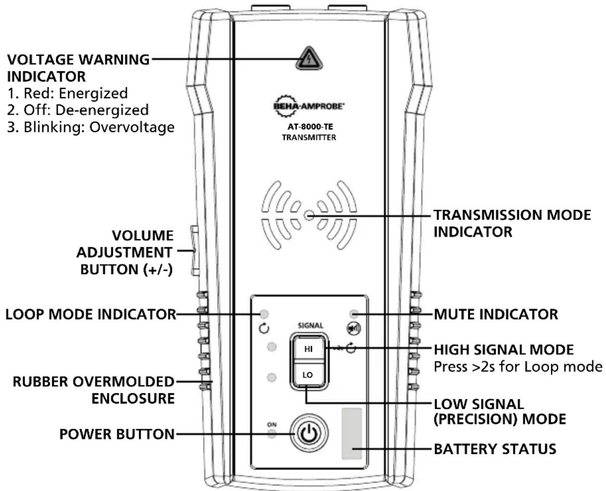
2.2 AT-8000-TE Transmitter
The AT-8000-TE Transmitter works on Energized and De-energized circuits up to 600 V AC/DC in Category I through Category IV electrical environments.
text_image
VOLTAGE WARNING INDICATOR 1. Red: Energized 2. Off: De-energized 3. Blinking: Overvoltage BEHA-AMPROBE® AT-8000-TE TRANSMITTER TRANSMISSION MODE INDICATOR VOLUME ADJUSTMENT BUTTON (+/-) LOOP MODE INDICATOR MUTE INDICATOR SIGNAL HI LO HIGH SIGNAL MODE Press >2s for Loop mode RUBBER OVERMOLDED ENCLOSURE LOW SIGNAL (PRECISION) MODE POWER BUTTON ON BATTERY STATUSFigure 2.3: Overview of AT-8000-TE Transmitter
ON/OFF: Short press to turn the Transmitter on. Long press >2s to turn the Transmitter off.
Volume adjustment: The volume can be changed by short presses on VOLUME UP/DOWN buttons. In addition to mute, four volume levels are available. The chosen volume level will be shown on LED display for a short time. If sound is muted, the MUTE LED light will be on. The sound pattern is different depending on chosen operating mode.
Voltage Warning indicator: The warning light will be ON for Energized circuits (30 to 600 V AC/DC), OFF for De-energized circuits (0 > 30 V AC/DC), and BLINKING if an overvoltage is detected (> 650 V AC/DC).
TRANSMISSION MODE INDICATOR: The LEDs will blink with different rhythm depending on the chosen operating mode.
Transmitting in HIGH mode – Fast blinking
Transmitting in LOW mode – Slow blinking
Transmitting in LOOP mode – Alternating blinking
High mode: Short press on HI to turn on HIGH transmitting mode. Second short press on HI button to turn off transmitting.
Low mode: Short press on LO to turn on LOW transmitting mode. Second short press on LO button to turn off transmitting.
Loop mode: Long press (>2s) on HI to turn on Loop mode. Short or long press on HI button to turn off Loop mode.
Transmitter signal modes:
High Signal (Hi) – The HIGH mode function is recommended for most wire tracing applications on Energized and De-energized circuits including breaker/fuse location. This function will be used the majority of the time.
Low Signal (Lo) – The LOW mode function is only appropriate for the most demanding and precise wire tracing applications, as it limits the signal level generated by the Transmitter in order to pinpoint the wire location more precisely. A lower signal level reduces coupling to neighboring wires and metal objects, which avoids misreadings due to ghost signals. A lower signal also prevents oversaturating the Receiver with a strong signal that covers too large of an area.
Loop mode – This mode is initiated by pressing and holding the HI button for >2 seconds. It should be used when working with closed loop De-energized circuits, such as shorted wires, shielded cables or De-energized wires that are grounded on the far-end.
How is the Loop function different from the Hi or Lo settings when using test leads?
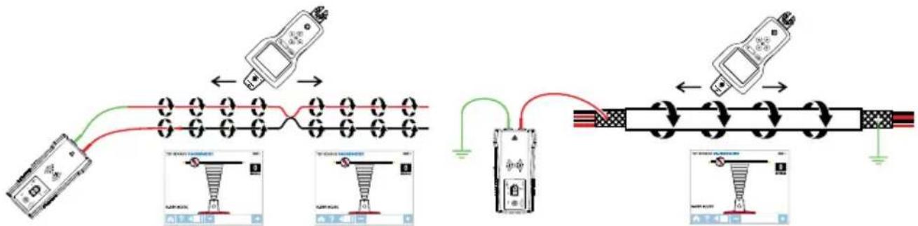
Both HIGH and LOW modes generate a signal in all open branches of the De-energized circuit. This is useful when tracing open wires. Hi/Lo modes will NOT work on wires that are shorted (closed loop) or grounded on the far-end because the signal cannot be generated.
text_image
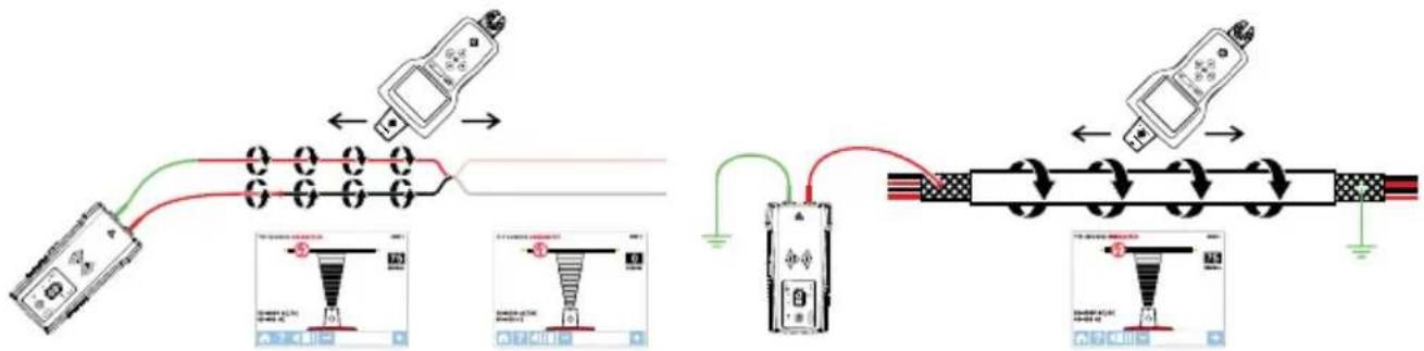
Diagram illustrating a cable connection and wiring setup with labeled components and wiring diagramsFigure 2.2a: Generating a signal with HIGH and LOW modes and closed loop Loop mode generates a signal (current flow) in closed loop De-energized circuits only. Loop mode is used to pinpoint the location of a short (because the current will not be able to flow in open branches) and to trace wires that are grounded on the far end (because the loop is closed via ground connection).
text_image
Diagram illustrating cable connection and wire routing with labeled components and wiring diagramsFigure 2.2b: Generating a signal in Loop mode
Note: Loop mode only works on De-energized circuits. It is automatically disabled when the Transmitter is connected to an Energized line with test leads.
Working with the Transmitter
When the Transmitter is on and connected to the circuit with test leads, it checks for voltage. A red Voltage Warning Indicator will light up if the Transmitter detects dangerous voltage levels above 30 V AC/DC.
IMPORTANT!
The Voltage Warning Indicator light will blink when overvoltage (> 650 V AC/DC) is detected. In case of overvoltage immediately disconnect the Transmitter from the circuit.
This Voltage Waning Indicator is not desinged to check for absence of voltage. Please use a voltage tester therefore.
If the High (HI) or Low (LO) Signal button is pressed momentarily, the Transmitter starts generating a tracing signal. Based on the detected voltage, the Transmitter automatically switches to either:
- Energized mode (30 to 600 V AC/DC) generating 6 kHz frequency
- De-energized mode (0 to 30 V AC/DC) generating 33 kHz frequency
Energized mode uses a lower transmission frequency (6 kHz) than De-energized mode (33 kHz) to reduce signal coupling between wires. De-energized mode requires a higher frequency in order to generate a reliable signal.
Energized mode: In Energized mode, the Transmitter draws a very low current from the Energized circuit and generates a 6 kHz signal. This is a very important feature of the Transmitter, since drawing current does not inject any signal that would harm sensitive equipment connected to the circuit. The signal is also generated in a direct path between the Transmitter and the power source, thus NOT placing a signal onto any branches enabling wiring tracing directly back to the breaker/fuse panel. Please note that due to this feature, the Transmitter has to be connected on the load side of the circuit.
De-energized mode: In De-energized mode, the Transmitter injects a 33 kHz signal onto the circuit. In this mode, the signal will travel though all the circuit branches because it is injected. The high frequency/low energy signal will not harm any sensitive equipment.
2.3 CT-400-EUR Signal Clamp
(included with AT-8030-EUR, optional for AT-8020-EUR)
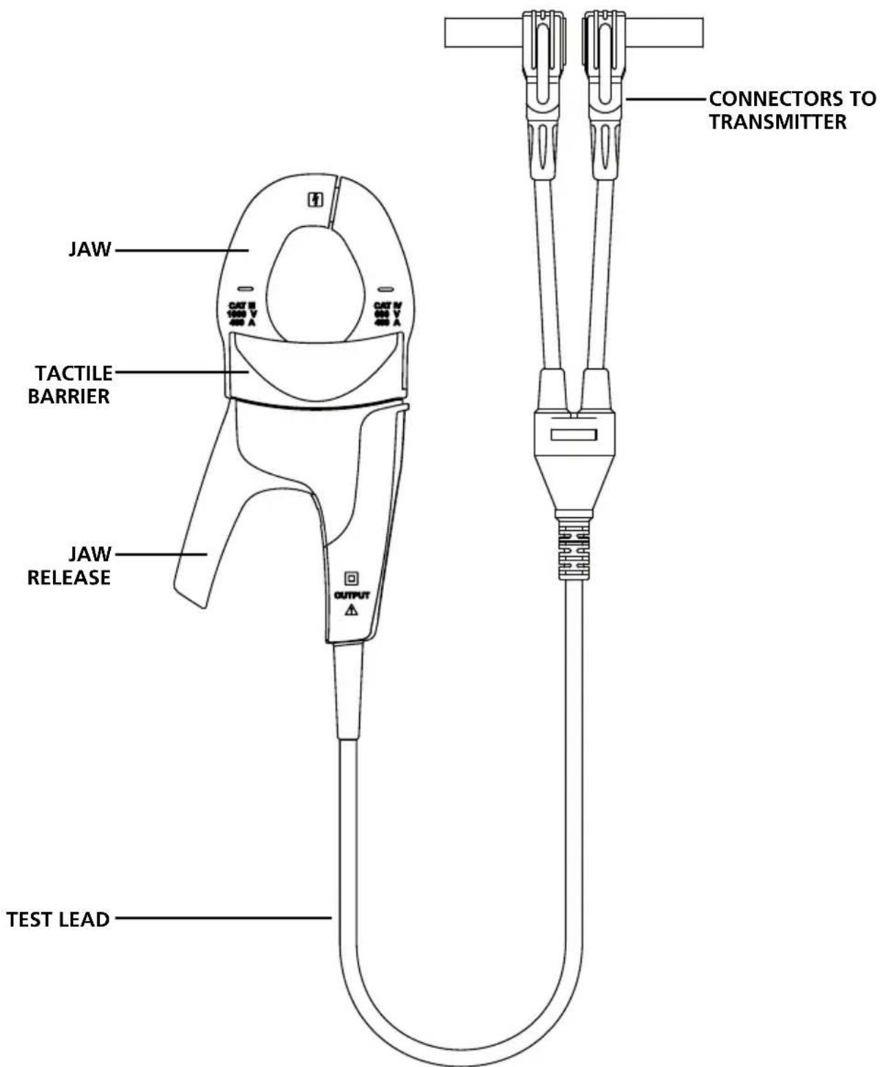
The Signal Clamp accessory is used for applications when where is no access to the bare conductors. The clamp attachment enables the Transmitter to induce a signal through the insulation into either wires. The clamp works on low impedance closed circuits.
text_image
CONNECTORS TO TRANSMITTER JAW TACTILE BARRIER JAW RELEASE TEST LEADFigure 2.3: Overview of CT-400-EUR Signal Clamp
⚠️ IMPORTANT NOTICE, PLEASE READ BEFORE STARTING TRACING
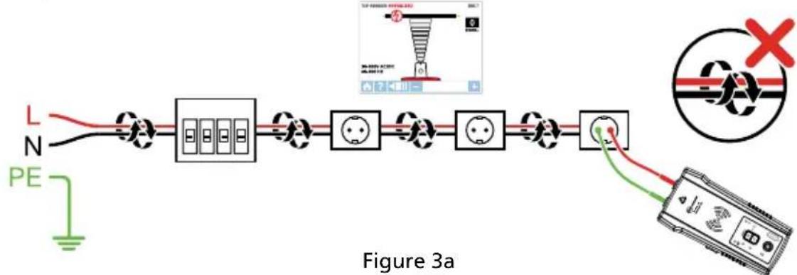
Avoiding signal cancellation problems with a separate neutral or separate ground connection
The signal generated by the Transmitter creates an electromagnetic field around the wire. This field is what is detectable by the Receiver. The clearer this signal, the easier it is to trace the wire. If Transmitter is connected to two adjacent wires on the same circuit (for example, line/phase and neutral wires), the signal travels in one direction through the first wire and then returns (in opposite direction) through the second. This causes the creation of two electromagnetic fields around each wire with opposite direction. These opposing fields will partially or completely cancel each other out, making wire tracing difficult if not impossible.
flowchart
graph LR
    A["L"] --> B["Switch"]
    C["N"] --> B
    B --> D["Grid of 3x5 blocks"]
    D --> E["Switch"]
    F["PE"] --> G["Ground"]
    H["Switch"] --> I["Switch"]
    I --> J["Switch"]
    J --> K["Switch"]
    K --> L["Switch"]
    L --> M["Switch"]
    M --> N["Switch"]
    N --> O["Switch"]
    O --> P["Switch"]
    P --> Q["Switch"]
    Q --> R["Switch"]
    R --> S["Switch"]
    S --> T["Switch"]
    T --> U["Switch"]
    U --> V["Switch"]
    V --> W["Switch"]
    W --> X["Switch"]
    X --> Y["Switch"]
    Y --> Z["Switch"]
    Z --> AA["Switch"]
    AA --> AB["Switch"]
    AB --> AC["Switch"]
    AC --> AD["Switch"]
    AD --> AE["Switch"]
    AE --> AF["Switch"]
    AF --> AG["Switch"]
    AG --> AH["Switch"]
    AH --> AI["Switch"]
    AI --> AJ["Switch"]
    AJ --> AK["Switch"]
    AK --> AL["Switch"]
    AL --> AM["Switch"]
    AM --> AN["Switch"]
    AN --> AO["Switch"]
    AO --> AP["Switch"]
    AP --> AQ["Switch"]
    AQ --> AR["Switch"]
    AR --> AS["Switch"]
    AS --> AT["Switch"]
    AT --> AU["Switch"]
    AU --> AV["Switch"]
    AV --> AW["Switch"]
    AW --> AX["Switch"]
    AX --> AY["Switch"]
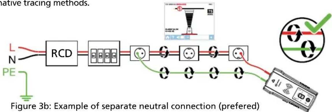
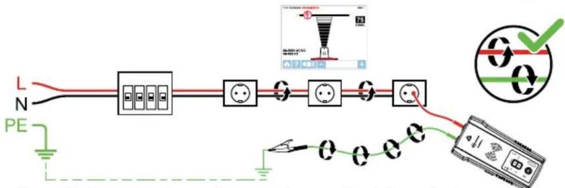
To avoid the cancellation effect, a separate neutral or separate ground connection method should be used. The red test lead of the Transmitter should be connected to the line/phase wire of the circuit you wish to trace, and the green lead to a separate ground or neutral (such as water pipe, ground stake, metal grounded structure of the building, or ground connection of an outlet) on a different branch. It is important to understand that an acceptable separate neutral/ground is NOT the terminal of any receptacle on the same branch as the wire you wish to trace. If line/phase wire is Energized and the Transmitter is properly connected to a separate neutral/ground, the red LED on the Transmitter will light up. The separate neutral/ground connection creates maximum signal strength because the electromagnetic field created around the line/phase wire is not being cancelled by a signal on the return path flowing along an adjacent wire (ground or neutral) in the opposite direction, but rather through the separate connection.
TIP: In circuits protected by RCD you must use always separate neutral connection instead of separate ground connection. Otherwise you will trip RCD.
Please refer also to Special Applications, section 4.1 "RCD-Protected Circuit Wire Tracing" for alternative tracing methods.
flowchart
graph LR
    A["L"] --> B["RCD"]
    C["N"] --> B
    D["PE"] --> B
    B --> E["Grid of 8 blocks"]
    E --> F["Power Source"]
    F --> G["Grid of 6 blocks"]
    G --> H["Power Source"]
    H --> I["Grid of 5 blocks"]
    I --> J["Power Source"]
    J --> K["Grid of 4 blocks"]
    K --> L["Power Source"]
    L --> M["Grid of 3 blocks"]
    M --> N["Power Source"]
    N --> O["Grid of 2 blocks"]
    O --> P["Power Source"]
    P --> Q["Grid of 1 block"]
    Q --> R["Power Source"]
    R --> S["Grid of 0 blocks"]
    S --> T["Power Source"]
    T --> U["Grid of 0 blocks"]
    U --> V["Power Source"]
    V --> W["Grid of 0 blocks"]
    W --> X["Power Source"]
    X --> Y["Grid of 0 blocks"]
    Y --> Z["Power Source"]
    Z --> AA["Grid of 0 blocks"]
    AA --> AB["Power Source"]
    AB --> AC["Grid of 0 blocks"]
    AC --> AD["Power Source"]
    AD --> AE["Grid of 0 blocks"]
    AE --> AF["Power Source"]
text_image
L N PE 0 0 0 0 0 0 0 0 0 0 0 0 0 0 0 0 0 0 0 0 0 0 0 0 0 0 0 0 0 0 0 0 0 0 0 0 0 0 0 0 0 0 0 0 0 0 0 0 0 0 0 0 0 0 1 0 0 0 1 0 0 1 0 1 0 1 0 1 0 1 0 1 0 1 0 1 0 1 0 1 0 1 0 1 0 1 0 1 0 1 0 1 0 1 0 1 0 1 0 1 0 1 0 1 0 1 0 1 0 1 0 1Figure 3c: Example of separate ground connection (alternative)
3.1 Tracing Energized Wires
Connecting transmitter test leads
- Connect the green and red test leads to the Transmitter (polarity does not matter).
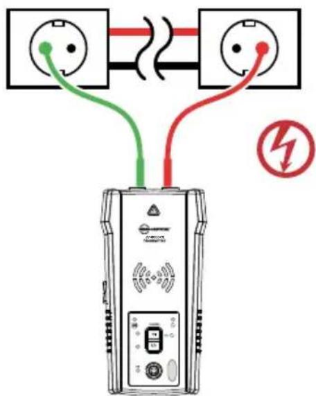
- Using provided test leads accessories, connect the red test lead to the line/phase wire being traced. For Energized systems the signal will ONLY be transmitted between the load-side to which the Transmitter is connected and the source of power (see Figure 3.1a).
- Connect green lead to a separate neutral wire at the RCD or at a connection point as close to the RCD as it is possible.*
*Note: Please make sure that line/phase wire and separate neutral are connected to the same RCD, otherwise the RCD will trip.
Check if the voltage warning indicator is ON. Otherwise the connection you have done is from line/phase to line/phase or from neutral to neutral or circuit is de-engergized. In this case redo the connection in the proper way.
text_image
Diagram showing connections between two electrical outlets with colored wires and a battery, including a fault symbol.Figure 3.1a: Proper connection with separate neutral
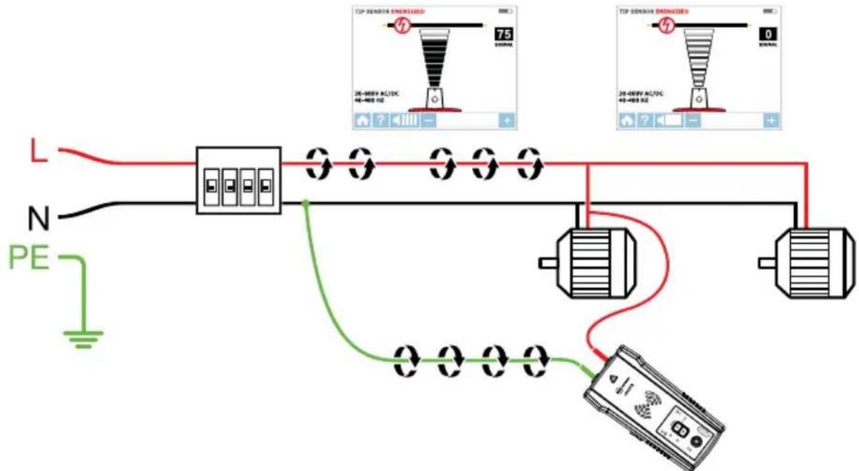
TIP: The Transmitter, with the red test lead, can be directly connected to the live wire of the working electrical equipment under load (motor, electronics, etc). Tracing can be performed without needing to turn off the equipment or switching power off.
text_image
L N PE 75 36-400V AC/DC 48-489 Hz 75 36-400V AC/DC 48-489 Hz 0 TIP SENSOR ENGRATED TIP SENSOR ENGRIDERS TIP SENSOR ENGRIDERS TIP SENSOR ENGRIDERS TIP SENSOR ENGRIDERS TIP SENSOR ENGRIDERS TIP SENSOR ENGRIDERS TIP SENSOR ENGRIDERS TIP SENSOR ENGRIDERS TIP SENSOR ENGRIDERS TIP SENSOR ENGRIDERS TIP SENSOR ENGRIDERS TIP SENSOR ENGRIDERS TIP SENSOR ENGRIDERS TIP Sensor ENGRATED TIP Sensor ENGRIDERS TIP Sensor ENGRIDERS TIP Sensor ENGRIDERS TIP Sensor ENGRIDERSFigure 3.1b: Transmitter set up
Set up the AT-8000-TE Transmitter
- Press power button to turn on the Transmitter.
-
Verify that the test leads are properly connected; the red LED voltage status light should be on for circuits with voltage above 30 V AC/DC.
Note: Make sure to use the separate neutral connection as described above. -
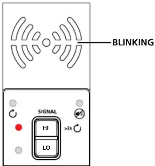
Select HIGH signal mode by pressing HI for most applications. The Transmitter will appear as shown in Figure 3.1c. The LED display will quickly begin to blink.
Note: The LOW signal precision mode can be used to limit the signal level generated by the Transmitter in order to more precisely pinpoint wire location. A lower signal level reduces coupling to neighboring wires and metal objects and helps to avoid misreading due to ghost signals. A lower signal also helps to prevent oversaturating the Receiver with a strong signal that covers too large an area. The LOW mode function is only used for the most demanding and precise wire tracing applications.
text_image
BLINKING SIGNAL HI >2s LOFigure 3.1c: Transmitter indicator showing signal in HIGH mode
3.1 a Using AT-8000-RE Receiver in Energized SMART SENSOR™ mode ④
The Smart Sensor™ enables easier wire tracing by showing the direction and position of the wire and is the recommended method for tracing Energized wires.
Note: The Smart Sensor ^TM does not work on de-energized circuits; Tip Sensor should be used instead.
Using AT-8000-RE Receiver
- Press power button to turn on the Receiver; home screen may take up to 30 seconds to load.
- Select SMART SENSOR ^TM mode by using the directional arrows and pressing the yellow ENTER button.
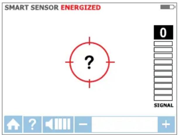
- Hold the Receiver with the Smart Sensor™ facing the target area. If the screen flashes a “?” in a red target then no signal is detected (Figure 3.1d). Move the Smart Sensor™ closer to the target area until the signal is detected and you see a directional arrow. If no signal is detected increase the sensitivity using the “+” button on the Receiver.*
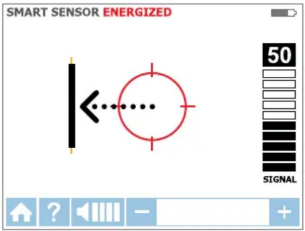
- Move the Receiver in direction indicated by the arrow on the screen (Figure 3.1e).
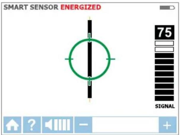
- A green target symbol indicates that the Receiver is directly over the wire. If the Receiver does not lock on the wire, decrease sensitivity using the "-" on the keypad or set the Transmitter to transmit at LOW level for precision tracing (Figure 3.1f).
- Press ENTER when complete to return to the home screen.
*Note: For best results, keep the Receiver at least 1 m (3 feet) from the Transmitter and its test leads to minimize signal interference and improve wire tracing results. Select the "Long" Smart Sensor™ Range in the Settings Menu if working with wires that are greater than 1 m (3 feet) deep.
text_image
SMART SENSOR ENERGIZED 0 SIGNALFigure 3.1d: No signal detected
text_image
SMART SENSOR ENERGIZED 50 SIGNALFigure 3.1e: Wire is to the left
text_image
SMART SENSOR ENERGIZED 75 SIGNALFigure 3.1f: Receiver locked on wire
3.1 b Using AT-8000-RE Receiver in Energized Tip Sensor mode
TIP SENSOR mode is used for the following applications: pinpointing a wire in a bundle, tracing in corners and confined spaces such as junction boxes or inside enclosures.
- Press power button to turn on the Receiver; home screen may take up to 30 seconds to load.
- Select Energized TIP SENSOR mode by using the directional arrows and pressing the yellow ENTER button.
- Hold the Receiver with the Tip Sensor facing the target area.
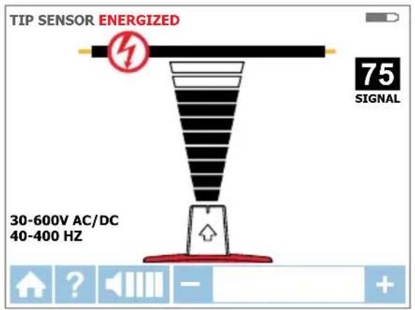
- Scan target area with Tip Sensor to find highest signal level (Figure 3.1g). While tracing, periodically adjust sensitivity to keep signal strength near 75. Increase or decrease sensitivity by pressing + or – on the keypad. If signal is too strong for precise locating, change transmitter to LOW mode.
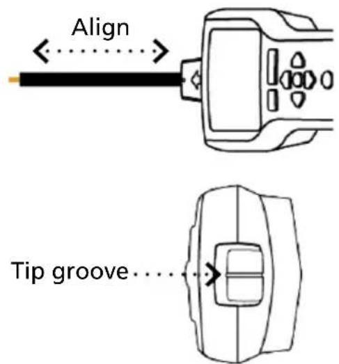
- Receiver Positioning: For best results, align groove on Tip Sensor with wire direction. Signal may be lost if not properly aligned (Figure 3.1h).
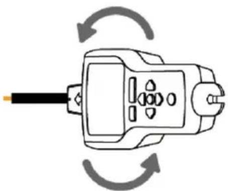
- To verify wire direction, periodically rotate the Receiver 90 degrees. Signal strength will be highest when wire is aligned with Tip Sensor groove (Figure 3.1i).
- Press ENTER when complete to return to the home screen.
Note: For best results, keep the Receiver at least 1 m (3 feet) from the Transmitter and its test leads to minimize signal interference and improve wire tracing results.
text_image
TIP SENSOR ENERGIZED 75 SIGNAL 30-600V AC/DC 40-400 HZFigure 3.1g: Receiver screen showing signal detected in Energized TIP SENSOR mode
text_image
Align Tip groove...Figure 3.1h: Aligning the Tip Sensor with the wire
natural_image
Diagram of a plug electrical socket with circular arrows indicating rotation (no text or symbols)Figure 3.1i: Rotating the Receiver to align with the wire
3.2 Tracing De-energized Wires
Connecting Transmitter test leads
- Connect green and red test leads to the transmitter (polarity does not matter)
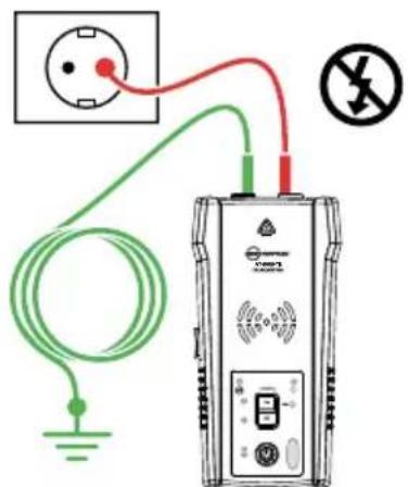
- Connect red lead to de-energized line/phase wire (on the load side of the system). In de-energized mode the signal will be injected to ALL branches of the circuit, not just between the outlet and the breaker/fuse as in energized modes.
- Connect green lead to a separate ground (metal building structure, metal water pipe, or ground wire / Protective Ground (PE) on a separate circuit).
ATTENTION: Due to safety reasons this is only allowed in de-energized circuits. Do not use a ground wire that runs in parallel to the wire you are going to trace, as it will reduce or cancel tracing signal.
text_image
Diagram showing electrical connections with a power outlet, wires, and a device labeled with symbols like 'No' and prohibition symbol.Figure 3.2a: Proper connection with separate ground
*Note: If working with energized RCD protected circuits, separate ground connection will trip the RCD.
Set up the AT-8000-TE Transmitter
- Press power button to turn on the Transmitter.
-
Verify that the test leads are properly connected; the red LED voltage status light should be off for De-energized circuits below 30 V AC/DC.
Note: Make sure to use the separate ground connection as described above. -
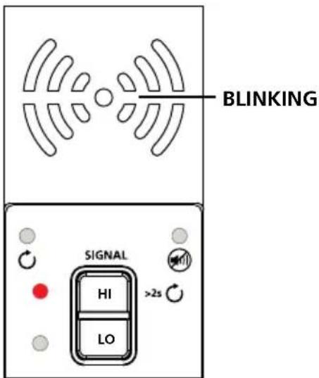
Select HIGH signal mode by pressing HI for most applications. The Transmitter will appear as shown in Figure 3.2b. The LED display will quickly begin to blink.
Note: The LOW signal precision mode can be used to limit the signal level generated by the Transmitter in order to more precisely pinpoint wire location. A lower signal level reduces coupling to neighboring wires and metal objects and helps to avoid misreading due to ghost signals. A lower signal also helps to prevent oversaturating the Receiver with a strong signal that covers too large an area. The LOW mode function is only used for the most demanding and precise wire tracing applications.
text_image
BLINKING SIGNAL HI >2s LOFigure 3.2b: Transmitter indicator showing signal in HIGH mode
Using AT-8000-RE Receiver in De-energized Tip Sensor mode
TIP SENSOR
De-energized TIP SENSOR mode is used for general wire tracing, pinpointing wires in bundles, tracing in tight corners and confined spaces such as junction boxes or inside enclosures.
- Press power button to turn on the Receiver; home screen may take up to 30 seconds to load.
- Select De-Energized TIP SENSOR mode by using the directional arrows and pressing the yellow ENTER button.
- Hold the Receiver with the Tip Sensor facing the target area.*
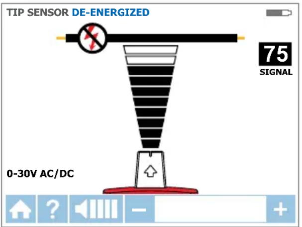
- Scan target area with Tip Sensor to find highest signal level (Figure 3.2c). While tracing, periodically adjust sensitivity to keep signal strength near 75. Increase or decrease sensitivity by pressing + or – on the keypad. If signal is too strong for precise locating, change transmitter to LOW mode.
- Press ENTER when complete to return to the home screen.
text_image
TIP SENSOR DE-ENERGIZED 75 SIGNAL 0-30V AC/DCFigure 3.2c: Receiver showing signal detected in De-energized TIP SENSOR mode
*Note: For best results, keep the Receiver at least 1 m (3 feet) from the Transmitter and its test leads to minimize signal interference and improve wire tracing results.
De-energized mode uses a different antenna in the Tip Sensor than Energized mode. Specific alignment of the Tip Sensor groove to the wire is not required. De-energized wire tracing results are based only on how close the Tip Sensor is to the wire.
3.3 Identifying Breakers and Fuses
Breaker mode automatically adjusts the sensitivity of the Receiver. As a result, the Receiver will pinpoint and indicate just one correct breaker/fuse. This enhancement helps to remove signal strength analysis from the breaker/fuse identification process that is typical for less advanced wire tracers.
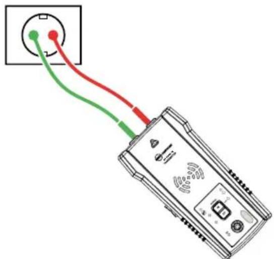
Note: For breaker/fuse locating, a simplified direct connection to Line and Neutral wires can be used because these wires are separated at the breaker/fuse panel. There is no risk of signal cancellation effect if wires are at least a few centimeters (inches) away from each other. However the separate Neutral connection as shown in Energized TIP SENSOR mode should be used for superior results specifically if wires need to be traced in addition to breaker/fuse identification.
natural_image
Diagram of a device with three colored wires (green, red, yellow) connecting a circular component to an electronic device (no text or symbols visible)Figure 3.3a: Simplified direct connection
Transmitter connection - Energized and De-energized systems
Connection of the Transmitter is the same for Energized and De-energized breaker/fuse locating.
Connecting the test leads
- Connect the Transmitter using either simplified direct connection or separate neutral/ground connection.
- If the simplified direct connection method is used, connect the test leads directly to the line/phase and neutral wires. While locating a breaker or fuse the wires will not be traceable as the signals will cancel each other out.
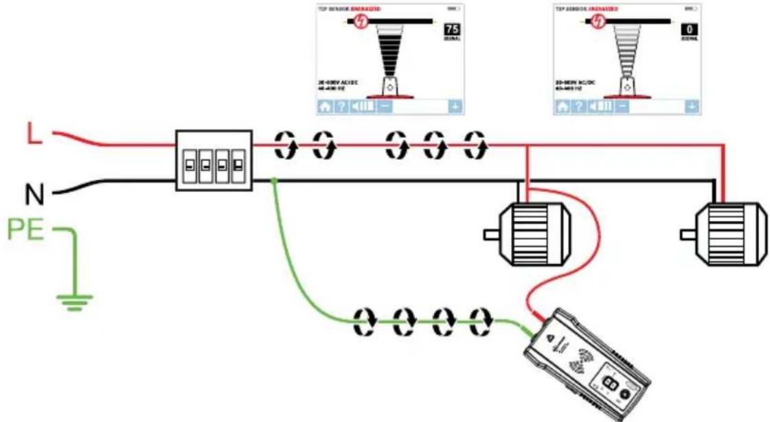
- For separate neutral connection, connect the red lead to the line/phase wire on the load side of the system. The wire can be Energized or De-energized. Connect the green lead to a separate neutral, such as a neutral wire as close to the breakers/fuse as it is possible.
TIP: The Transmitter, with the red test lead, can be directly connected to the live wire of the working electrical equipment under load (motor, electronics, etc). Tracing can be performed without needing to turn off the equipment or switching power off.
text_image
L N PE 75 60 20-800V AC/DC 40-400 VZ TIP SENSOR ENRATED 75 60 20-800V AC/DC 40-400 VZ TIP SENSOR ENRATED 75 60 20-800V AC/DC 40-400 VZSet up the AT-8000-TE Transmitter
- Press the power button to turn on the Transmitter.
- Verify that the test leads are properly connected. The red LED voltage status light will illuminate for Energized circuits with a voltage above 30 V AC/DC. If the voltage is De-energized, the light will be off.
- Select the HIGH signal mode for breaker/fuse locating.
Energized and De-energized breaker/fuse locating
BREAKERS &
Receiver Process Overview
Tracing breakers/fuses is a two-step process:
① SCAN - Scan each breaker/fuse for one second. The Receiver will record tracing signal levels.
② LOCATE - The Receiver will indicate the single breaker/fuse with the strongest recorded signal.
Using AT-8000-RE Receiver
- Press power button to turn on the Receiver; home screen may take up to 30 seconds to load.
- Select either Energized BREAKERS mode or De-Energized BREAKERS mode by using the directional arrows and pressing the yellow ENTER button.
Step 1 - ① SCAN
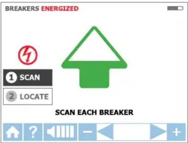
- The unit will automatically start in ① SCAN mode (Figure 3.3c).
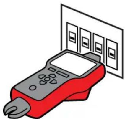
- Scan each breaker/fuse for a second by touching it with the Tip Sensor. Make sure the groove on the Tip Sensor is parallel to the breaker/fuse lengthwise (Figure 3.3e).
- To assure sufficient time between the scans, wait for active green arrow and audible alert (2 beeps) before moving to the next breaker/fuse.
- Scan all breakers/fuses – the order of scanning does not matter. You can scan each breaker/fuse multiple times. The Receiver records the highest detected signal.
Usage tip: For best results try to scan at the output of the breaker/fuse.
Important note: Differentiation in breaker/fuse designs, height, internal contact structure may affect precision of breaker/fuse identification. For most reliable results, remove the breaker/fuse panel cover and perform scan on the wires instead of breakers/fuses. Scan the breakers/fuses always at the same position and alignment of the tip sensor. A variation may affect improper results.
text_image
BREAKERS ENERGIZED ① SCAN ② LOCATE SCAN EACH BREAKERFigure 3.3c: SCAN mode – Scanning breakers/fuses
natural_image
Illustration of a red handheld payment terminal with four digital display panels above it (no text or symbols)Figure 3.3e: Correct alignment of the Tip Sensor to the breaker
Step 2 - ② LOCATE
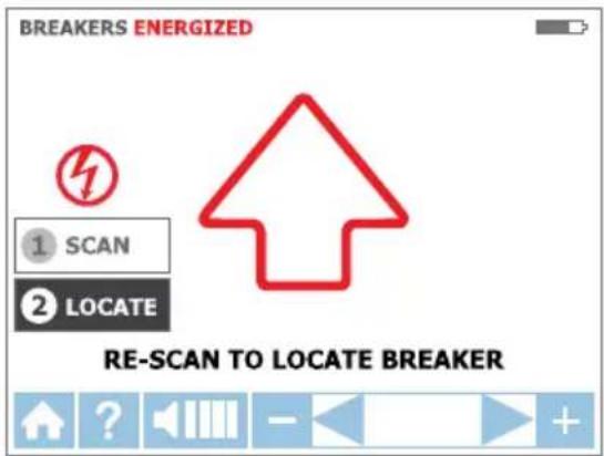
- Select LOCATE mode by using the directional arrows and pressing the yellow ENTER button (Figure 3.3d).
- Rescan each breaker/fuse by touching each with the Tip Sensor for a second. Active red arrow indicates scanning process. Make sure the groove on the Tip Sensor is parallel to the breaker/fuse lengthwise (Figure 3.3e).
Usage Tip: Hold receiver in the same position as during scanning step
-
Rescan all breakers/fuses until solid green arrow and audible alert (continuous beep) indicates that the correct breaker/fuse was found (Figure 3.3f).
-
Press ENTER when complete to return to the home screen.
text_image
BREAKERS ENERGIZED ① SCAN ② LOCATE RE-SCAN TO LOCATE BREAKERFigure 3.3d: LOCATE mode – Searching for correct breaker/fuse
Usage Tip: The accuracy of breaker/fuse identification results can be verified by switching the Receiver to Energized or De-Energized TIP SENSOR mode and checking that that the signal level of the breaker identified by the Receiver is the highest among all breakers/fuses.
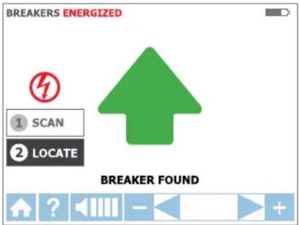
text_image
BREAKERS ENERGIZED ① SCAN ② LOCATE BREAKER FOUNDFigure 3.3f: LOCATE mode – breaker/fuse identified
3.4 NCV Mode
The NCV (Non-Contact Voltage) mode is used to verify that a wire is Energized. This method does not require the use of the Transmitter. The Receiver will detect and trace an Energized cable if the voltage is between 90 V and 600 V AC and between 40 Hz and 400 Hz. No current flow is necessary.
Note: For safety, before working with wires, always verify that they are De-energized with an additional voltage tester.
⚠️ The voltage indication in NCV mode is not sufficient to assure safety. This function is not suitable to test for absence of voltage. This always requires a two-pole voltage test.
NCV mode operation
- Press power button to turn on the Receiver; home screen may take up to 30 seconds to load.
- Press NCV button to select the Non-Contact Voltage mode.
- Hold the Receiver with the Tip Sensor against the wire.
- For precise pinpointing of line/phase wire versus neutral wire, increase or decrease sensitivity by pressing + or - on the keypad.
- Press ENTER when complete to return to the home screen.
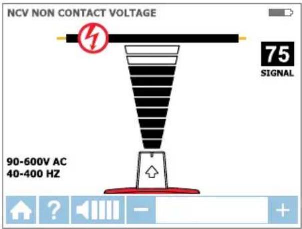
text_image
NCV NON CONTACT VOLTAGE 75 SIGNAL 90-600V AC 40-400 HZFigure 3.4: Voltage detection in NCV mode using Tip Sensor
4.1 RCD-Protected Circuit Wire Tracing
Method 1
- Whenever possible use separate neutral connection. For this connect green test lead to a separate neutral wire at the RCD or at a connection point as close to the RCD as it is possible.*
- Perform tracing as described in the Wire Tracing (SMART and TIP SENROR modes) or Breaker/Fuse applications.
*Note: Please make sure that line/phase wire and separate neutral are connected to the same RCD, otherwise the RCD will trip.
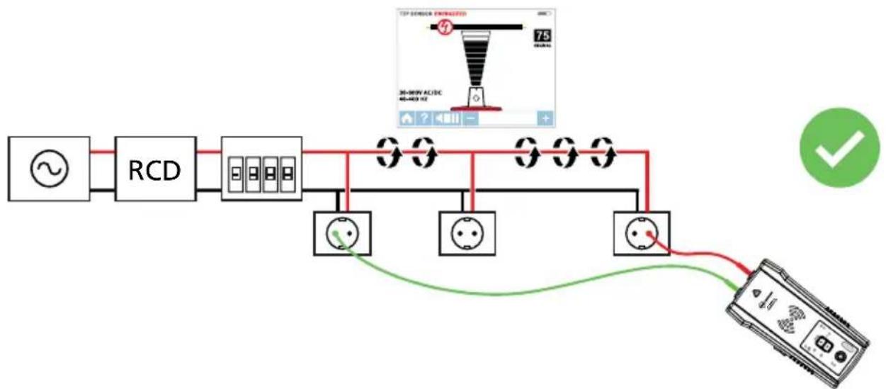
flowchart
graph LR
    A["AC Source"] --> B["RCD"]
    B --> C["Terminal Block 1"]
    C --> D["Terminal Block 2"]
    D --> E["Terminal Block 3"]
    E --> F["Terminal Block 4"]
    F --> G["Terminal Block 5"]
    G --> H["Terminal Block 6"]
    H --> I["Terminal Block 7"]
    I --> J["Terminal Block 8"]
    J --> K["Terminal Block 9"]
    K --> L["Terminal Block 10"]
    L --> M["Terminal Block 11"]
    M --> N["Terminal Block 12"]
    N --> O["Terminal Block 13"]
    O --> P["Terminal Block 14"]
    P --> Q["Terminal Block 15"]
    Q --> R["Terminal Block 16"]
    R --> S["Terminal Block 17"]
    S --> T["Terminal Block 18"]
    T --> U["Terminal Block 19"]
    U --> V["Terminal Block 20"]
    V --> W["Terminal Block 21"]
    W --> X["Terminal Block 22"]
    X --> Y["Terminal Block 23"]
    Y --> Z["Terminal Block 24"]
    Z --> AA["Terminal Block 25"]
    AA --> AB["Terminal Block 26"]
    AB --> AC["Terminal Block 27"]
    AC --> AD["Terminal Block 28"]
    AD --> AE["Terminal Block 29"]
    AE --> AF["Terminal Block 30"]
    AF --> AG["Terminal Block 31"]
    AG --> AH["Terminal Block 32"]
    AH --> AI["Terminal Block 33"]
    AI --> AJ["Terminal Block 34"]
    AJ --> AK["Terminal Block 35"]
    AK --> AL["Terminal Block 36"]
    AL --> AM["Terminal Block 37"]
    AM --> AN["Terminal Block 38"]
    AN --> AO["Terminal Block 39"]
    AO --> AP["Terminal Block 40"]
    AP --> AQ["Terminal Block 41"]
    AQ --> AR["Terminal Block 42"]
    AR --> AS["Terminal Block 43"]
    AS --> AT["Terminal Block 44"]
    AT --> AU["Terminal Block 45"]
    AU --> AV["Terminal Block 46"]
    AV --> AW["Terminal Block 47"]
    AW --> AX["Terminal Block 48"]
    AX --> AY["Terminal Block 49"]
    AY --> AZ["Terminal Block 50"]
Figure 4.1: Example of separate neutral connection
Method 2 – If separate neutral connection is not practical:
- De-energize the circuit.
- Connect a transmitter directivity to the wire as described in Wire Tracing method for de-energized wires using separate ground connection (green test lead connected to the separate ground instead of neutral wire).
- Perform tracing as described in the Wire Tracing or Breaker/Fuse applications.
4.2 Finding Breaks/Opens
It is possible to pinpoint the exact location where a wire is broken, even if the wire is located behind walls, floors or ceilings.
- Make sure that wire is De-energized.
- Use the steps described in section 3.2 to connect the Transmitter and perform tracing.
- For best results, ground all De-energized wires that run in parallel with the black test lead. The tracing signal generated by the Transmitter is conducted along the wire as long as there is continuity in the metal conductor. To find a fault, trace the wire until the signal stops. To verify the fault's location, move the Transmitter to the other end of the wire and repeat, tracing from the opposite end. If signal stops at the exact same location, the fault has been located.
Note: If the place of the fault is not found, the result may be a high resistance break (partially open circuit). Such a break would stop higher currents from flowing but will conduct the tracing signal through the break. Such faults will not be detected until the wire is completely open.
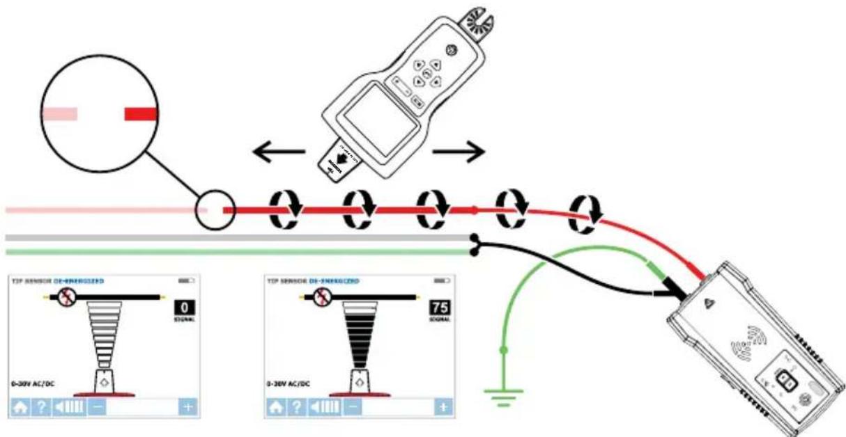
flowchart
graph TD
    A["Sensor Detection"] --> B["Device Placement"]
    B --> C["Signal Output"]
    D["Image Display: TIP Sensor DE-FEREGIZED"] --> E["0-30V AC/DC Signal"]
    F["Image Display: TIP Sensor DE-FEREGIZED"] --> G["0-30V AC/DC Signal"]
    H["Image Display: 75% Signal"] --> I["Ground"]
Figure 4.2: Locating the place of the fault
4.3 Finding Shorts
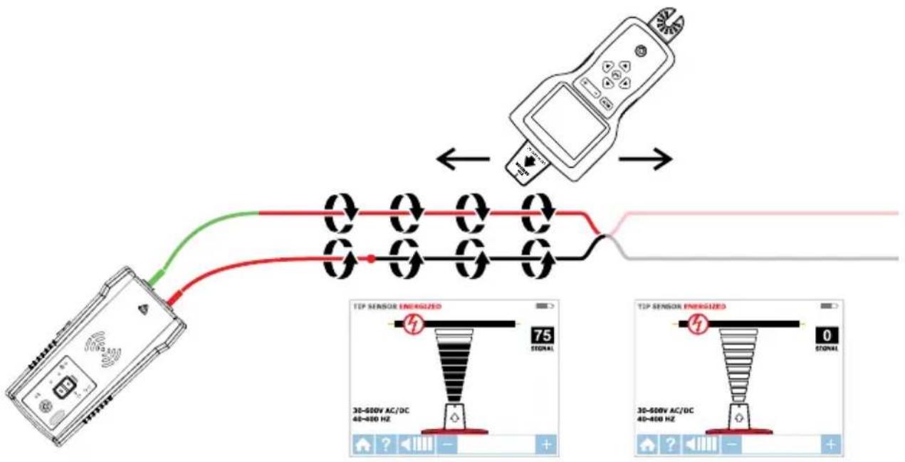
Shorted wires will cause a breaker/fuse to trip. To correct this, disconnect the wires and make sure the ends of the wires on both sides of the cable are isolated from each other and other wires or loads and are De-energized.
- Connect the Transmitter with the test leads to the circuit as shown in Figure 4.3.
- Turn the Transmitter to Loop mode by pressing HIGH button for two seconds. Verify that the Loop LED is ON.
- Set the receiver to De-Energized TIP SENSOR mode and perform tracing.
Start tracing the cable until the signal stops. To verify the place of the fault, move the Transmitter to the other end of the wire and repeat tracing from the opposite end. If the signal stops at the exact same location the fault has been located.
Note: This method will be affected by signal cancellation effect. Expect a relatively weak signal.
flowchart
graph TD
    A["Device"] --> B["Signal"]
    B --> C["Analog Device"]
    C --> D["TEP Sensor Energyized: 75% STONAL\n30-500V AC/DC\n40-400 Hz"]
    D --> E["TEP Sensor Energyized: 0% STONAL\n30-500V AC/DC\n40-400 Hz"]
Figure 4.3: Finding a short
4.4 Tracing Wires in Metal Conduit: Junction Box Method
The AT-8000-RE Receiver will not be able to pick up the signal from the wire through the metal conduit. The metal conduit will completely shield the tracing signal.
Note: The Receiver will be able to detect wires in non-metallic conduit. For these applications follow general tracing guidelines.
In order to trace wires in conduit:
- Use either Energized or De-energized TIP SENSOR mode as described in sections 3.1 b and 3.2.
- Open junction boxes and use the Receiver's Tip Sensor to detect which wire in the junction box is carrying the signal.
- Move from junction box to junction box to follow the path of the wire.
Note: Applying signal directly to the conduit will send signal through all the conduit branches making tracing of one particular conduit path not possible.
4.5 Tracing Non-Metallic Pipes and Conduits
The AT-8000-EUR can indirectly trace plastic conduits and pipes using the following steps:
- Insert conductive fish tape or wire inside the conduit.
- Connect the Transmitter's red test lead to the fish tape and the green ground wire to a separate ground as described in section 3.2.
-
Set the Receiver to De-energized TIP SENSOR mode to trace the conduit.
-
The Receiver will pick up the signal conducted by fish tape or wire through the conduit.
4.6 Tracing Shielded Wires
Shielded wires prevent the Receiver from detecting a tracing signal when following the standard user instructions. To effectively trace shielded wire, follow these procedures.
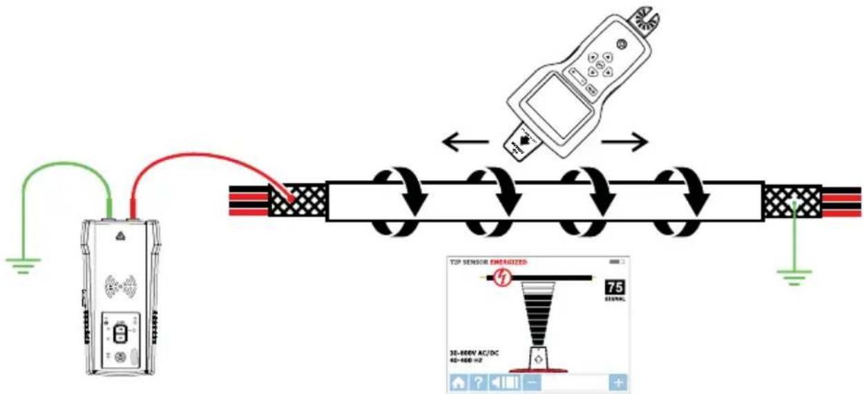
If shielded wire is grounded at the far-end:
- Setup Transmitter in Loop mode by pressing HIGH button for two seconds. Verify that the Loop LED is ON.
- Disconnect the ground on the near-end of the shielded wire and connect the shield to one of the terminals of the Transmitter (polarity does not matter) with a test lead.
- Connect the second output of the Transmitter to a separate ground.
- Set the Receiver to De-energized TIP SENSOR mode to trace the shield as described in section 3.2.
flowchart
graph LR
    A["Antenna"] --> B["Switch"]
    B --> C["Sensor"]
    C --> D["Handheld Device"]
    D --> E["Signal Output: 75%"]
    style A fill:#f9f,stroke:#333
    style B fill:#ccf,stroke:#333
    style C fill:#cfc,stroke:#333
    style D fill:#fcc,stroke:#333
    style E fill:#ffc,stroke:#333
Figure 4.6a: Tracing a shielded wire
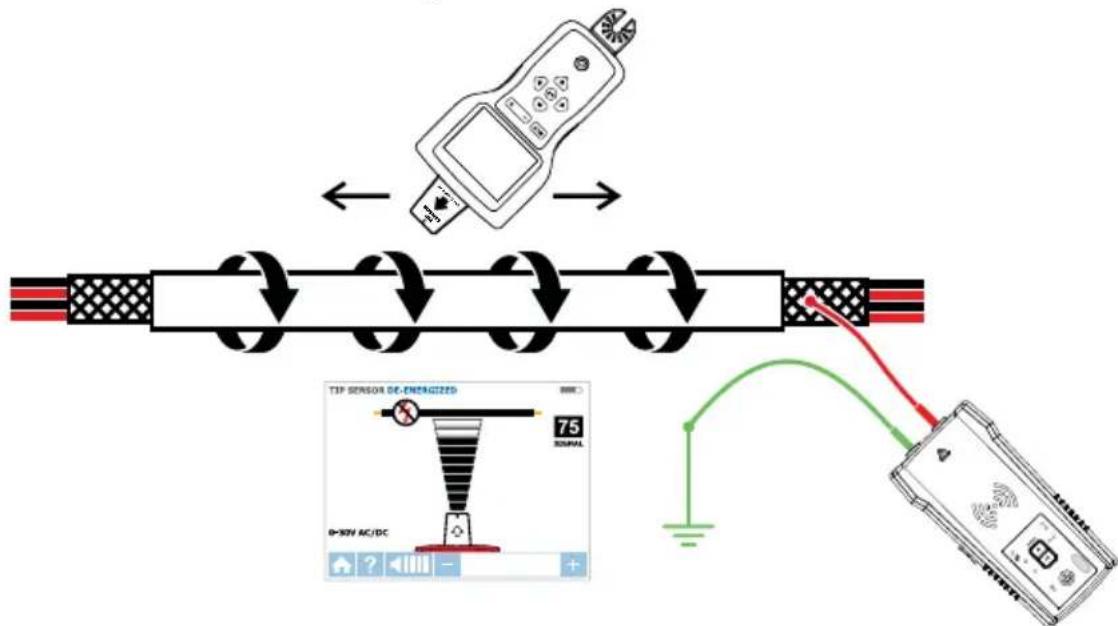
If shielded wire is disconnected from ground at the far-end:
- Setup the Transmitter in Wire Tracing mode (see section 3.2).
- Disconnect the ground on the near-end of the shielded wire and connect the shield to one of the terminals of the Transmitter (polarity does not matter) with a test lead.
- Connect the second output of the Transmitter to a separate ground.
- Set the Receiver to a wire tracing mode to trace the shield as described in section 3.2.
flowchart
graph TD
    A["Electric shock hazard test"] --> B["Switch"]
    B --> C["DC-ENERGIZED device with 75% power supply"]
    C --> D["Battery connected to battery"]
    style A fill:#f9f,stroke:#333
    style B fill:#ccf,stroke:#333
    style C fill:#cfc,stroke:#333
    style D fill:#fcc,stroke:#333
Figure 4.6b: Tracing a shielded wire disconnected from ground at the far-end
4.7 Tracing Underground Wires
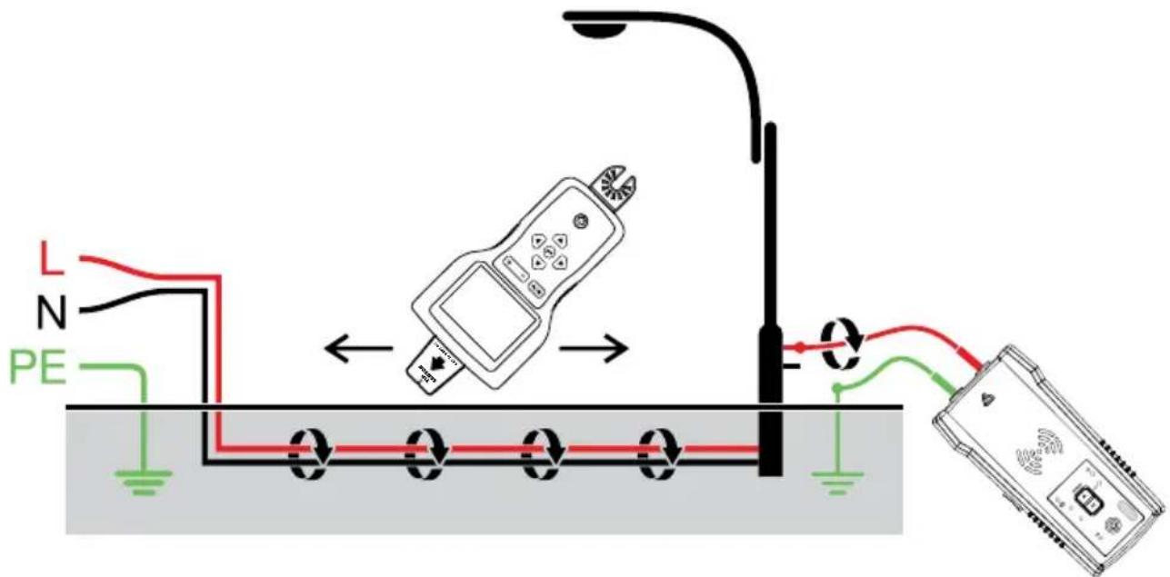
The AT-8000-EUR can trace wires underground, the same way it can locate wires behind walls or floors.
Perform tracing as described in Energized SMART SENSOR™ mode or Energized / De-Energized TIP SENSOR modes.
You can use a hot sick attachment to make tracing more ergonomic and convenient.
text_image
L N PEFigure 4.7: Tracing underground wires
4.8 Tracing Low Voltage Wires and Data Cables
The AT-8000-EUR can trace data, audio, and thermostat cables (to trace shielded data cables, refer to section 4.6).
Trace data, audio, and thermostat cables:
- Connect the Transmitter using the separate ground method described in section 3.2.
- Set the Receiver to De-energized TIP SENSOR mode and trace the wire.
4.9 Sorting Bundled Wires
Identifying a specific wire in a bundle:
- Connect the Transmitter using Energized or De-Energized TIP SENSOR mode. If connecting to energized wire, make sure the Transmitter is connected on the load side.
- Select respectively Energized or De-energized TIP SENSOR mode on the Receiver. Pull one wire out as far as possible from other wires in the bundle and touch it with the Tip Sensor. The strongest signal indicates the proper wire in the bundle.
Note: In some special cases it may be necessary to connect all unused de-energized wires on the transmitter side to ground.
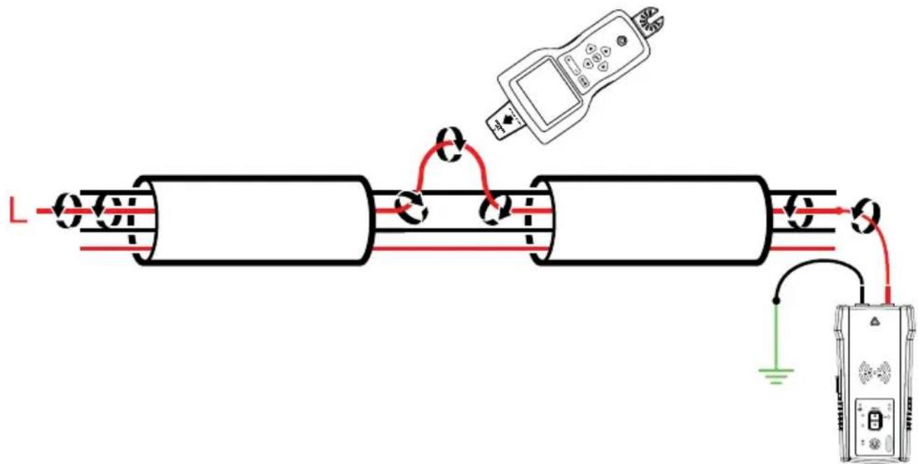
text_image
Diagram of a mechanical or electrical testing setup with labeled components and wiring connections4.9a: Identifying a energized wire
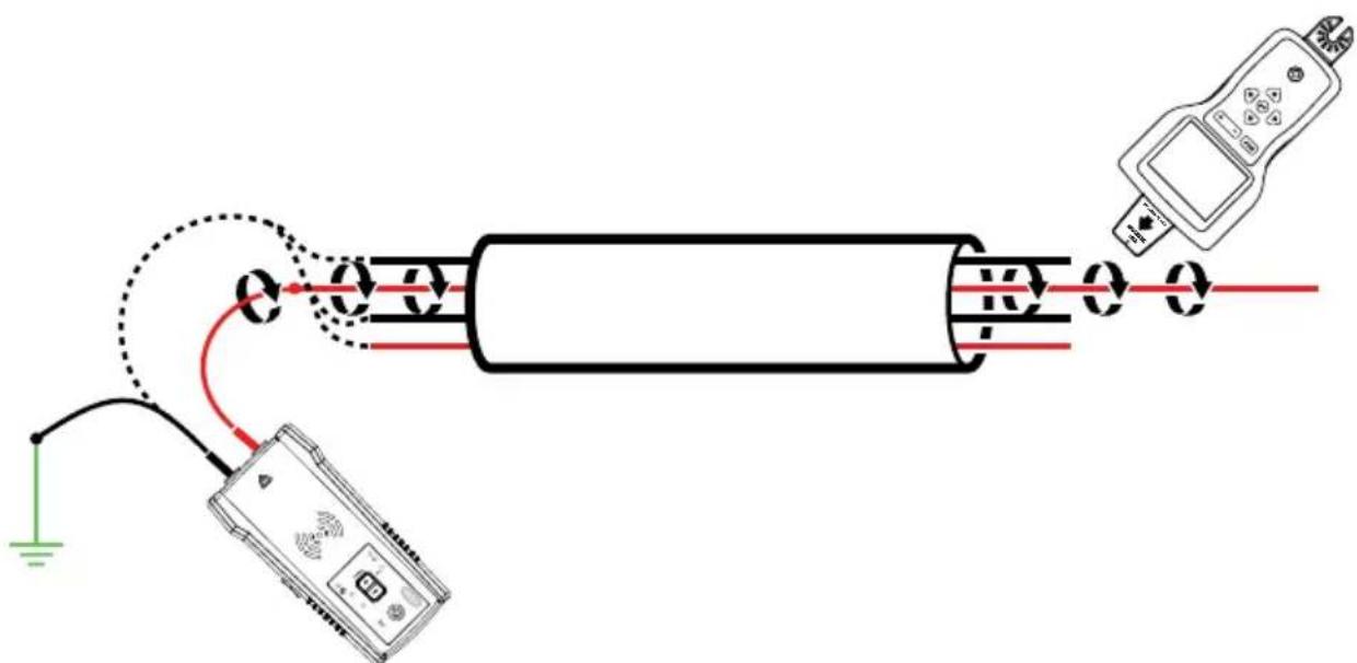
text_image
Diagram showing electrical connections between a device and a handheld device, with labeled components and wiring paths.4.9b: Identifying a de-energized wire
4.10 Mapping a Circuit using Test Leads Connection
Mapping a circuit can be only performed on a De-energized circuit when using test leads connection.
- Switch the breaker/fuse to the OFF position.
- Set up the Transmitter and Receiver as described in the De-energized Wire Tracing as described in section 3.2.
- Scan face plates of receptacles and wires towards load with the Tip Sensor of the Receiver
- All the wires, receptacles and loads that have a strong signal as indicated by the Receiver are connected to this breaker/fuse.
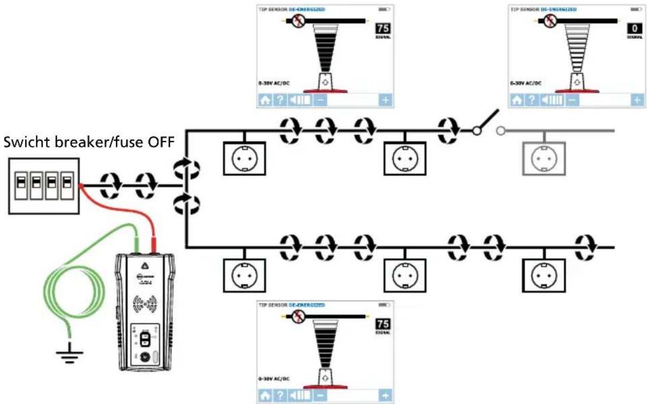
flowchart
graph TD
    A["Switch breaker/fuse OFF"] --> B["Dienergized Switch"]
    B --> C["TIP Sensor DE-ENERGIZED 75 V"]
    B --> D["TIP Sensor DE-ENERGIZED 0 V"]
    B --> E["TIP Sensor DE-ENERGIZED 75 V"]
    B --> F["TIP Sensor DE-ENERGIZED 0 V"]
    style A fill:#f9f,stroke:#333
    style B fill:#ccf,stroke:#333
    style C fill:#cfc,stroke:#333
    style D fill:#cfc,stroke:#333
    style E fill:#cfc,stroke:#333
    style F fill:#cfc,stroke:#333
Figure 4.10: Mapping a circuit
4.11 Tracing Breakers/Fuses on Systems with Light Dimmers
Light dimmers can produce a significant amount of electrical “noise” that consists of multifrequency signals. In some rare situations, the Receiver can misread this noise, often called a “ghost” signal, as a Transmitter - generated signal. Therefore, the Receiver may provide misleading readings. When locating breakers or fuses on systems with light dimmers, the dimmer should be off (the light switch is off). This prevents the Receiver from indicating a wrong breaker/fuse.
4.12 Signal Clamp - Closed Loop Circuits
Closed loop, De-energized and low impedance circuits
The clamp accessory is used for applications where there is no access to a bare conductor to connect the test leads. When the clamp is connected to the Transmitter, it enables the Transmitter to induce a signal to the Energized or De-energized wire through the insulation. Typical applications of the Signal Clamp include tracing conduits or shields grounded on both ends. For signal cables and De-energized wires or loads, temporarily ground the circuit on both ends to perform tracing.
Connecting the Signal Clamp
- Connect the CT-400-EUR test leads to the terminals of the Transmitter (polarity does not matter).
- Clamp the CT-400-EUR Signal Clamp around the conductor. To increase the signal strength, wind a few turns of the conductor wire around the clamp if possible.
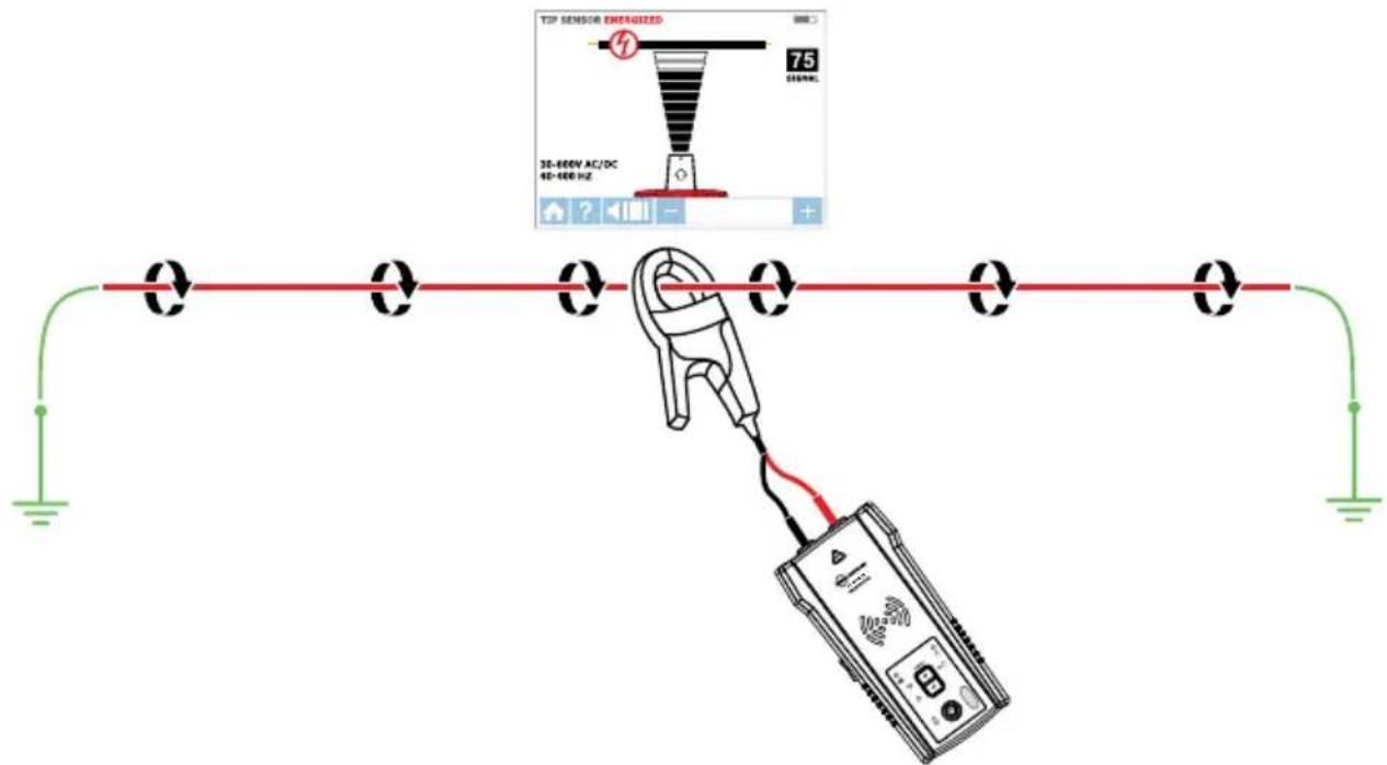
text_image
TOP SENSOR ENERGIZED 75 30-600V AC/DC 40-600 HzFigure 4.12a: Signal Clamp connection
Set up the AT-8000-TE Transmitter
- Press the power button to turn on the Transmitter. The red LED voltage status indicator should be OFF when the clamp is connected and when working with either Energized or De-energized systems.
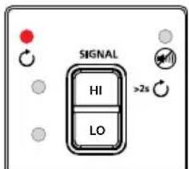
- Press HIGH signal mode and hold button for >2 seconds to select the Loop mode on the Transmitter. This clamp mode (loop mode) generates a boosted 6 kHz signal in order to provide superior tracing results.
text_image
SIGNAL HI LO >2sFigure 4.12b: Transmitter indicator showing signal in Loop mode
Using AT-8000-RE Receiver
- Press power button to turn on the Receiver; home screen may take up to 30 seconds to load.
- Select Energized TIP SENSOR mode by using the directional arrows and pressing the yellow ENTER button.
- Hold the Receiver with the Tip Sensor facing the target area.
- Scan target area with Tip Sensor to find highest signal level. While tracing, periodically adjust sensitivity to keep signal strength near 75. Increase or decrease sensitivity by pressing + or – on the keypad.
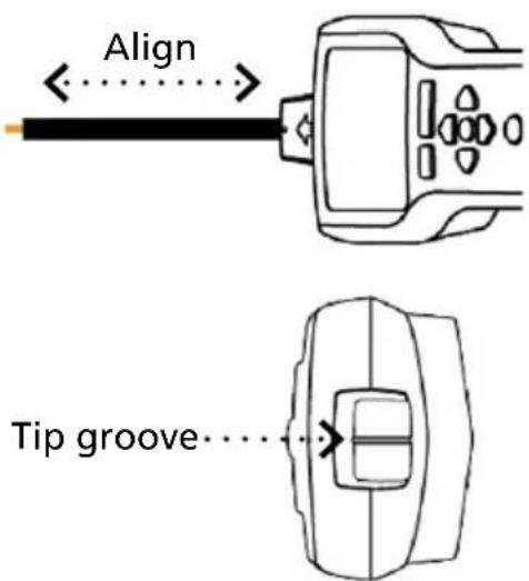
- Receiver Positioning: For best results, align groove on tip sensor with wire direction as shown. Signal may be lost if not properly aligned.
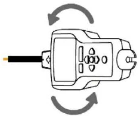
- To verify wire direction, periodically rotate Receiver 90 degrees. Signal strength will be highest when wire is aligned with Tip Sensor groove.
- Press ENTER when complete to return to the home screen.
text_image
Align Tip groove...Figure 4.12c: Aligning the Tip Sensor with the wire
natural_image
Diagram of a plug electrical socket with circular arrows indicating rotation (no text or symbols)Figure 4.12d: Rotating the Receiver to align with the wire
*Note: For best results, keep the Receiver at least 1 m (3 feet) from the Transmitter, Signal Clamp and its test leads to minimize signal interference and improve wire tracing results.
4.13 Signal Clamp - Mapping Circuits
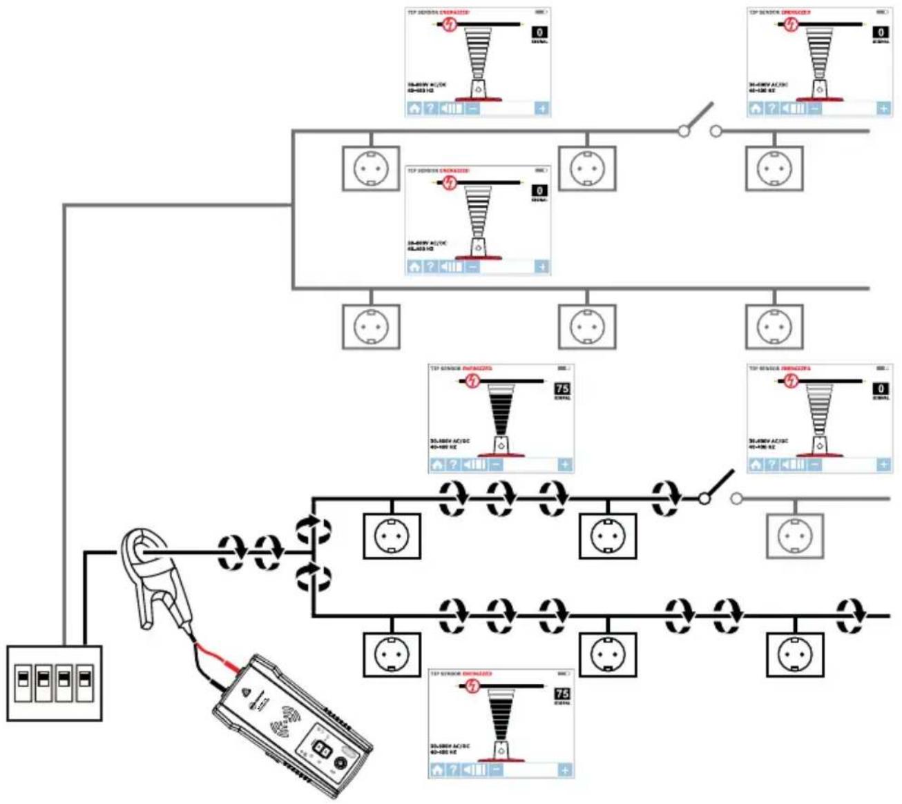
The clamp accessory can be used to map loads to specific breakers/fuses on both Energized and De-energized systems. There is no need to disconnect power.
- Clamp the CT-400-EUR around the wire at the breaker/fuse panel.
- Set up the Transmitter and Receiver as described in the previous section 4.12.
- Scan face plates of receptacles and wires connecting loads with the TIP Sensor of the Receiver. While using Loop mode you must set the Receiver to Energized TIP SENSOR mode.
- All the wires, receptacles and loads that have a strong signal as indicated by the Receiver are connected to this breaker/fuse.
flowchart
graph TD
    A["Terminal Block"] --> B["Inductor"]
    B --> C["Power Meter"]
    C --> D["Indicator Light"]
    D --> E["TCP SENSOR ENHANCED"]
    E --> F["Inductor 1"]
    E --> G["Inductor 2"]
    E --> H["Inductor 3"]
    E --> I["Inductor 4"]
    E --> J["Inductor 5"]
    E --> K["Inductor 6"]
    E --> L["Inductor 7"]
    E --> M["Inductor 8"]
    E --> N["Inductor 9"]
    E --> O["Inductor 10"]
    E --> P["Inductor 11"]
    E --> Q["Inductor 12"]
    E --> R["Inductor 13"]
    E --> S["Inductor 14"]
    E --> T["Inductor 15"]
    E --> U["Inductor 16"]
    E --> V["Inductor 17"]
    E --> W["Inductor 18"]
    E --> X["Inductor 19"]
    E --> Y["Inductor 20"]
    E --> Z["Inductor 21"]
    E --> AA["Inductor 22"]
    E --> AB["Inductor 23"]
    E --> AC["Inductor 24"]
    E --> AD["Inductor 25"]
    E --> AE["Inductor 26"]
    E --> AF["Inductor 27"]
    E --> AG["Inductor 28"]
    E --> AH["Inductor 29"]
    E --> AI["Inductor 30"]
    E --> AJ["Inductor 31"]
    E --> AK["Inductor 32"]
    E --> AL["Inductor 33"]
    E --> AM["Inductor 34"]
    E --> AN["Inductor 35"]
    E --> AO["Inductor 36"]
    E --> AP["Inductor 37"]
    E --> AQ["Inductor 38"]
    E --> AR["Inductor 39"]
    E --> AS["Inductor 40"]
    E --> AT["Inductor 41"]
    E --> AU["Inductor 42"]
    E --> AV["Inductor 43"]
    E --> AW["Inductor 44"]
    E --> AX["Inductor 45"]
Figure 4.13: Locating loads with the Signal Clamp
5.1 Battery Replacement
Changing the Transmitter Batteries
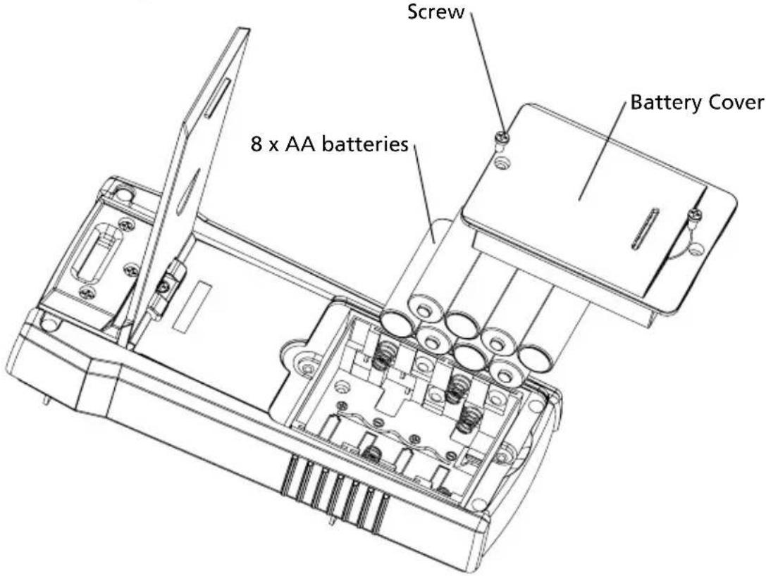
The battery compartment on the back of the Transmitter is designed to make it easy for the user to change the batteries. A screw is added to secure the battery in case the unit is dropped. Eight (8) AA alkaline or rechargeable NiMH batteries may be used. NiMH batteries need to be removed to be charged.
Note: Batteries do not come pre-installed in the Transmitter.
- Make sure that the Transmitter is turned off and disconnected from the circuit.
- Use a philips screw driver to unscrew the battery compartment screws.
- Remove the battery cover (Figure 5.1a).
- Install batteries.
- Replace the battery cover and secure it with the screws.
text_image
Screw Battery Cover 8 x AA batteriesFigure 5.1a: Changing Transmitter batteries
Manual Selecting of Transmitter Battery Type
The type of batteries being used-Alkaline or rechargeable NiMH-are recognized automatically during power up of the device or may be defined manually by the user.
Set battery type as alkaline:
- Make sure that the Transmitter is turned off.
- Press and hold the VOLUME UP (+) button.
- While volume up button is pressed, press the power button. The chosen battery type will be alkaline.
Set battery type as rechargeable NiMH:
- Make sure that the Transmitter is turned off.
- Press and hold the VOLUME DOWN (-) button.
- While volume down button is pressed, press the power button. The chosen battery type will be rechargeable NiMH.
If the battery type is not defined manually, it will be recognized automatically. Automatic battery type recognition draws more current and can be unreliable if inadequate or old batteries are used. The automatic battery recognition can also be unreliable if the rechargeable batteries have not been charged in over one month.
Transmitter Battery Status
Related to 8 AA batteries same type and connected in series.
BATTERY TRESHOLD ALKALINE
Device will power off if voltage is below 6.9 V
Battery empty – RED LED blinking if voltage is > 7.3 V and < 9.4 V
0-10% - RED LED is ON for voltages > 9.6 V and < 9.9 V
10-40% - Two yellow LEDs are ON for voltages > 10 V and < 10.8 V
40-75% - Three green LEDs are ON or voltages > 10.9 V and < 12 V
75% - Four green LEDs are ON for voltages > 12 V
BATTERY TRESHOLD NiMH
Device will power off if voltage is below 6.9 V
Battery empty – RED LED blinking if voltage is > 7.1 V and < 7.3 V
0-10% - RED LED is ON for voltages > 7.4 V and < 7.6 V
10-40% - Two yellow LEDs are ON for voltages > 7.7 V and < 8.5 V
40-75% - Three green LEDs are ON or voltages > 8.6 V and < 9.7 V
75% - Four green LEDs are ON for voltages > 9.8 V
Changing the Receiver Batteries
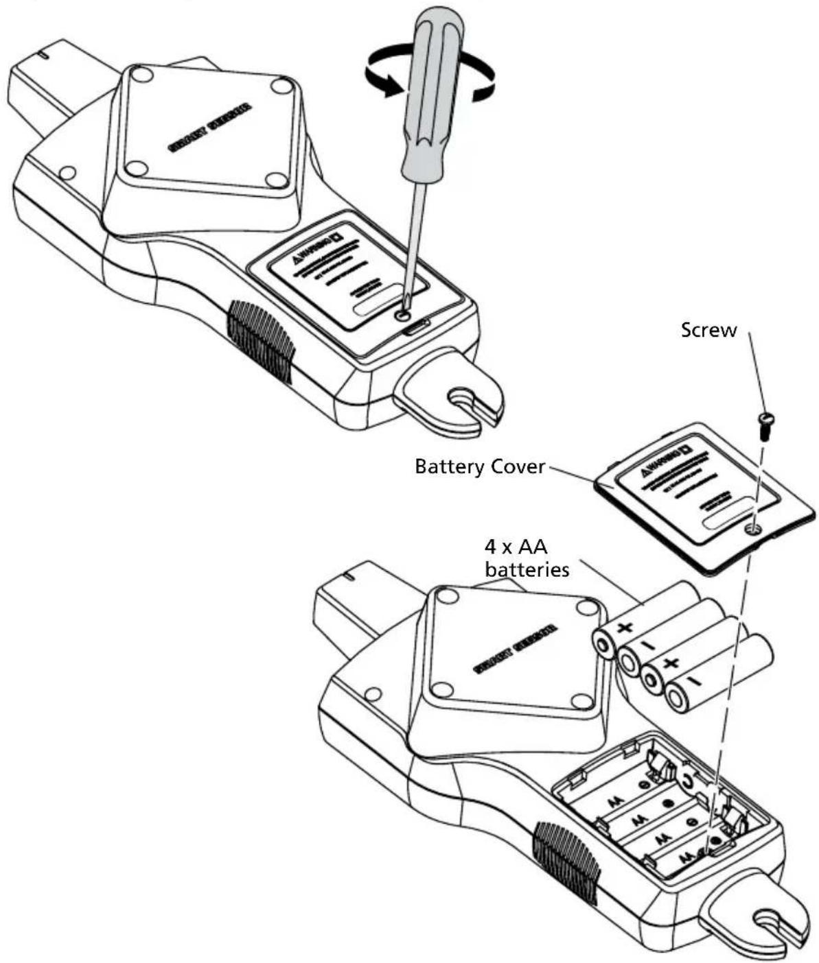
The battery compartment on the back of the Receiver is designed to make it easy for the user to change the batteries. A screw is added to secure the battery in case the unit is dropped. Four (4) AA alkaline or rechargeable NiMH batteries may be used. NiMH batteries need to be removed to be charged.
Note: Batteries do not come pre-installed in the Receiver.
- Make sure that the Receiver is turned off.
- Use flat screw driver to unscrew the captive screw.
- Remove the battery cover (Figure 5.1b).
- Install batteries.
- Replace the battery cover and secure it with the provided screw.
text_image
Screw Battery Cover 4 x AA batteriesFigure 5.1b: Changing Receiver batteries
5.2 Fuse Replacement
Transmitter Fuse Replacement
⚠ Warning: To avoid shock, injury, or damage to the Transmitter, disconnect test leads before opening case.
- Disconnect all test leads from the Transmitter.
- Make sure the Transmitter is turned off.
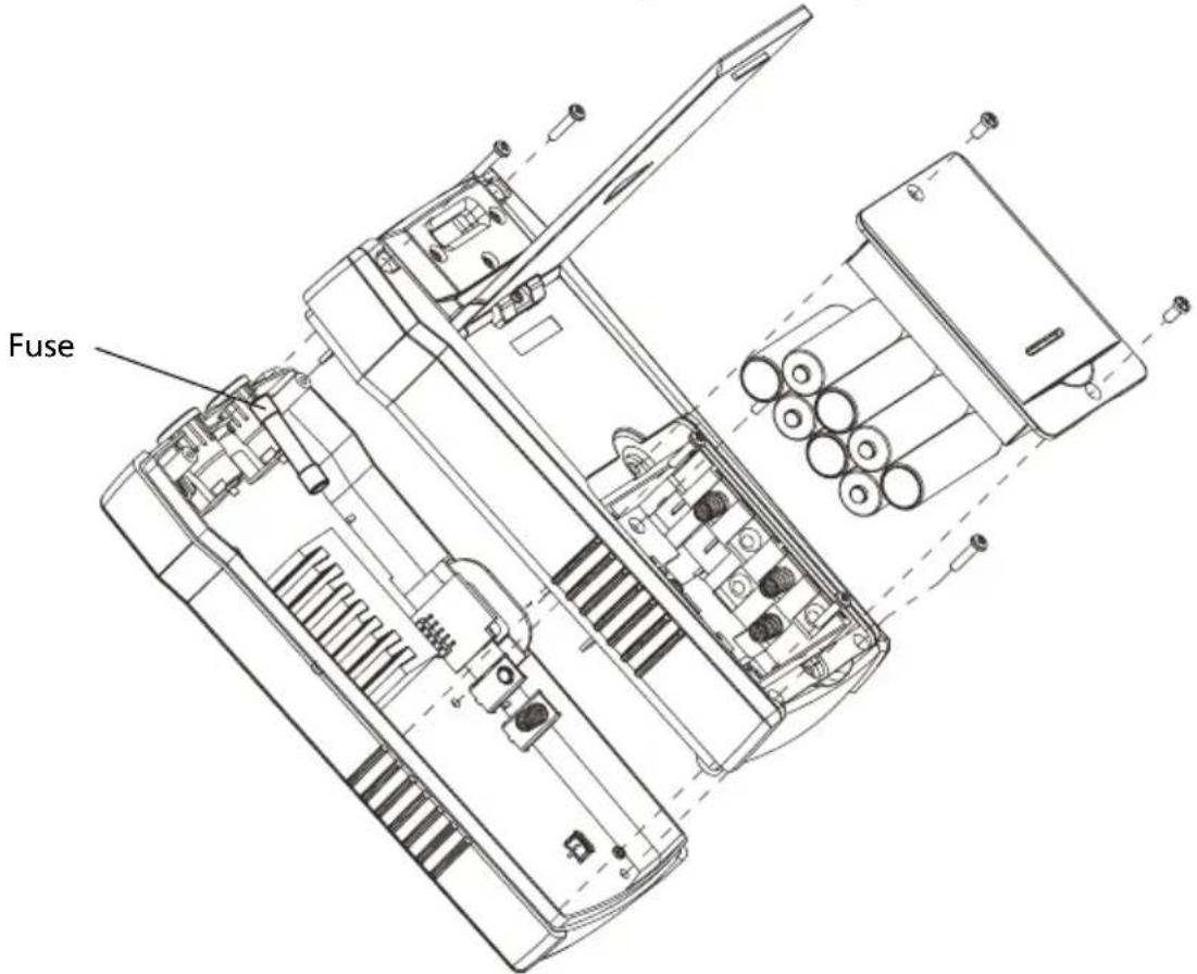
- Use a philips screw driver to unscrew the tilt-stand screws.
- Remove the battery door and remove all batteries.
- Use a philips screw driver to unscrew holding screws.
- Remove the back cover by pulling it upwards (Figure 5.2).
-
Remove the fuse from the fuse holder.
-
Insert the new fuse (1.6 A, 700 V MAX, FAST ∅ 6X32 mm) in the fuse holder.
-
Insert the back cover, secure it with the holding screws and tighten with a star screw driver.
text_image
FuseFigure 5.2: Transmitter fuse replacement
| Features AT-8000 | -RE AT-8000-TE CT-400-EUR | ||
| Measurement Category | CAT IV 600 V CAT IV 600 V | CAT IV 600 V, | CAT III 1000 V |
| Operating Voltage | 0 to 600 V AC/DC 0 to 600 V | AC/DC 0 to 1000 V AC | |
| Operating Frequency | Energized: 6.25 kHzDe-Energized: 32.768 kHz | Energized: 6.25 kHzDe-Energized: 32.768 kHz | Loop Mode: 6.25 kHzHigh / Low Mode: 32.768 kHzAC current measurement: 45 Hz to 400 Hz |
| Voltage Detection | See NCV detection > 30 V AC/DC N/A | ||
| Signal Indications | Numeric bar graph display and audible beep | LEDs and audible beep N/A | |
| Response Time | Smart mode: 750 mSecTip Sensor Energized: 300 mSecTip Sensor De-Energized: 750 mSecNCV: 500 mSecBattery monitoring: 5 Sec | Line voltage monitoring: 1 secBattery voltage monitoring: 5 sec | Instantaneous |
| Current Output of Signal (typical) | N/A | Energized circuit:HI mode: 60 mA RMSLO mode: 30 mA RMSDe-energized circuit:HI mode: 130 mA RMSLO mode: 40 mA RMSLoop mode: 160 mA RMS | 1 mA/A for AC current measurement with multimeter |
| Signal Voltage Output (nominal) | N/A | De-energized circuit:LOW: 29 V RMS, 120 Vp-pHIGH: 33 V RMS, 140 Vp-pWith CT-400-EUR:Loop mode: 31 V RMS, 120 Vp-p | De-energized circuit:2.4 V RMS, 24 Vp-p |
| Range Detection (open air) | Smart modePinpointing: Around 5 cm (1.97-in) radius ( ± 2% )Direction indication:Up to 1.5 m (5 FT) ( ± 2% )TIP Sensor: EnergizedPinpointing: Around 5 cm (1.97-in) ( ± 1% )Detection:Up to 6.7 m (22 FT) ( ± 1% )TIP Sensor: De-EnergizedDetection:Up to 4.3 m (14 FT) ( ± 5% )NCV (40-400 Hz)Pinpointing: Around 5 cm (1.97-in) radius ( ± 5% )Detection:Up to 1.2 m (4 FT) ( ± 5% ) | N/A N/A | |
General specifications
| Features AT-8000-RE | AT-8000-TE CT-400-EUR | ||
| Display Size | 89 mm (3.5 in) LEDs N/A | ||
| Display Dimensions(W x H) | 70 x 52 mm(2.76 x 2.07 in) | N/A N/A | |
| Display Resolution | 320 x 240 N/A N/A | ||
| Display Type | Color TFT LCD LEDs N/A | ||
| Display Color | Yes Operating mode LEDs: redBattery status LEDs:green, yellow, red | N/A | |
| Booting Time | 30 sec < 2 sec N/A | ||
| Backlight | Yes N/A N/A | ||
| Operating Temperature | -20 °C to 50 °C(-4 °F to 122 °F) | -20 °C to 50 °C(-4 °F to 122 °F) | 0 °C to 50 °C(32 °F to 122 °F) |
| Operating Humidity | 45%: -20 °C to <10 °C(-4 °F to <50 °F)95%: 10 °C to <30 °C(50 °F to <86 °F)75%: 30 °C to <40 °C(86 °F to <104 °F)45%: 40 °C to 50 °C(104 °F to 122 °F) | 45%: -20 °C to <10 °C(-4 °F to <50 °F)95%: 10 °C to <30 °C(50 °F to <86 °F)75%: 30 °C to <40 °C(86 °F to <104 °F)45%: 40 °C to 50 °C(14 °F to 122 °F) | 95%: 10 °C to <30 °C(50 °F to <86 °F)75%: 30 °C to <40 °C(86 °F to <104 °F)45%: 40 °C to 50 °C(104 °F to 122 °F) |
| Storage Temperature and Humidity | -20 °C to 70 °C(-4 °F to 158 °F), <95% RH | -20 °C to 70 °C(-4 °F to 158 °F), <95% RH | -20 °C to 60 °C(-4 °F to 140 °F), <95% RH |
| Operating Altitude | 0 to 2000 m (6561 ft) 0 to 2000 m (6561 ft) 0 to 2000 m | (6561 ft) | |
| Transient Protection | N/A 8.00 kV (1.2/50μS surge) N/A | ||
| Pollution Degree | 2 | 2 | 2 |
| IP Rating | IP 52 | IP 40 | IP 40 |
| Drop Test | 1 m (3.28 ft) | 1 m (3.28 ft) | 1 m (3.28 ft) |
| Power Supply | 4 x AA (alkaline or NiMH rechargeable) | 8 x AA (alkaline or NiMH rechargeable) | N/A |
| Power Consumption (typical) | 4 x AA battery: 2W | Hi/Lo mode: 70 mALoop mode with Clamp:90 mAConsumption without signal transmission: 10 mA | N/A |
| Battery Life (typical) | Approx. 9 h | Hi/Lo mode: approx. 25 hLoop mode: approx. 18 h | N/A |
| Low Battery Indication | Yes Yes N/A | ||
| Fuse | N/A 1.6 A, 700 V, fast-acting,∅ 6x32mm | N/A | |
| Maximum Conductor Size | N/A N/A 32 mm (1.26 in) | ||
| Dimensions(L x W x H) | Approx. 278 x 113 x 65 mm(10.92 x 4.43 x 2.55 in) | Approx. 183 x 93 x 50 mm(7.2 x 3.66 x 1.97 in) | Approx. 150 x 70 x 30 mm(5.9 x 2.75 x 1.18 in) |
| Weight(batteries installed) | Approx. 0.544 kg (1.20 lb) | Approx. 0.57 kg (1.25 lb) | Approx. 0.114 kg (0.25 lb) |
| Certifications | [CSK3]  [STD7] [STD7] |   [B363] [B363] |  [BGKC] [BGKC] |
Accessory specifications
| Features ADPTR-SCT TL-8000-EUR | ||
| Measurement Category | CAT II CAT IV 600 V (test leads) | CAT IV 600 V (alligator clips)CAT II 1000V (test probes) |
| Operating Voltage and Current | 102 to 253 V AC, 4 A max. 600 | V, 10 A max. (red/black leads)600 V, 6 A max. (green lead)600 V, 10 A max. (alligator clips)1000 V, 8 A max. (test probes) |
| Operating Temperature | 0 °C to 40 °C (32 °F to 104 °F) | °C to 50 °C (32 °F to 122 °F) |
| Operating Humidity | ≤ 80% RH 95%: 10 °C to <30 °C (50 °F to <86 °F)75%: 30 °C to <40 °C (86 °F to <104 °F)45%: 40 °C to <50 °C (104 °F to <122 °F) | |
| Storage Temperature and Humidity | 0 °C to 40 °C / 32 °F to 104 °F, ≤ 80% RH | -20 °C to 60 °C (-4 °F to 140 °F), <95% RH |
| Operating Altitude | 0 to 2000 m (6561 ft) 0 to 2000 | m (6561 ft) |
| Pollution Degree | 2 | 2 |
| IP Rating | IP 40 IP 20 | |
| Drop Test | 1 m (3.28 ft) 1 m (3.28 ft) | |
| Dimensions | Approx. 75 x 50 x 65 mm(2.95 x 1.97 x 2.56 in) | Red/black leads: 1 m (3.28 ft)Green lead: 7 m (22.97 ft)Alligator clips: approx. 95 x 45 x 24 mm(3.74 x 1.77 x 0.94 in)Test probe: approx. 134 x 23 x 14 mm(5.28 x 0.91 x 0.55 in) |
| Weight | Approx. 0.057 kg (0.125 lb) | approx. 0.25 kg (0.55 lb) |
| Certifications |   |   |
NR6 6JB United Kingdom
Telefon: +44 (0) 1603 25 6662
beha-amprobe.com
text_image
Diagram illustrating cable connection and waveform analysis with labeled components and waveformstext_image
Diagram illustrating a multi-wire electrical circuit with sensor connections and component diagrams, including labeled components and wiring paths.text_image
L N PE 0 0 0 0 0 0 0 0 0 0 0 0 0 0 0 0 0 0 0 0 0 0 0 0 0 0 0 0 0 0 0 0 0 0 0 0 0 0 0 0 0 0 0 0 0 0 0 0 0 0 13text_image
Diagram showing connections between two electrical outlets connected to a device with a fault symbol and warning iconnatural_image
Line drawing of a plug with circular ports and a cable, showing clockwise rotation arrows (no text or symbols)text_image
Diagram showing electrical connections with a power outlet, wires, and a device labeled with symbols like 'No' and prohibition symbol.natural_image
Diagram of a device with three colored wires (green, red, green) connecting a circular component to an electrical terminal block (no text or symbols)natural_image
Illustration of a red handheld payment terminal with four digital display panels above it (no text or symbols)text_image
Diagram illustrating a cable test setup with a device, sensor, and indicator display showing temperature range and voltage range.text_image
Diagram of a mechanical or electrical testing setup with labeled components and wiring connectionstext_image
Diagram showing electrical connections between a device and a mobile phone, with labeled components and wiring paths.natural_image
Diagram of a plug electrical socket with circular arrows indicating clockwise rotation (no text or symbols)NR6 6JB United Kingdom
Tel: +44 (0) 1603 25 6662
beha-amprobe.com
text_image
Diagram illustrating a cable connection and scanning process with labeled components and wiring diagramstext_image
Diagram illustrating a cable connection and measurement setup with labeled components and wiring connectionstext_image
L N PE Figure 2: Figure 1.5 Current-limiting Current-limiting Current-limiting Current-limiting Current-limiting Current-limiting Current-limiting Current-limiting Current-limiting Current-limiting Current-limiting Current-limiting Current-limiting Current-limiting Current-limiting Current-limiting Current-limiting Current-limiting Current-limiting Current-limiting Current-limiting Current-limiting Current-limiting Current-limiting Current-limiting Current-limiting Current-limiting Current-limiting Current-limiting Current-limiting Current-limiting Current-limiting Current-limiting Current-limiting C C C C C C C C C C C C C C C C C C C C C C C C C C C C C C C C C C C C C C C C C C C C C C C C C C C O O O O O O O O O O O O O O O O O O O O O O O O O Otext_image
Diagram showing connections between two electrical outlets connected to a device with a fault symbol and red line indicating connection.natural_image
Diagram of a plug electrical outlet with circular arrows indicating clockwise rotation (no text or symbols)text_image
Diagram showing electrical connections with a power outlet, wires, and a device labeled 'No' symbolnatural_image
Diagram of a device with three colored wires (green, red, green) connecting a circular component to an electronic device (no text or symbols visible)natural_image
Illustration of a red handheld electronic device with four square buttons and a screen, mounted on a wall (no text or symbols visible)text_image
Diagram showing a mechanical or electrical setup with labeled components and connections, including a digital thermometer and a multimeter.text_image
Diagram showing electrical connections between a device and a mobile phone, with labeled components and wiring paths.natural_image
Line drawing of a plug electrical socket with circular arrows indicating clockwise rotation (no text or symbols)NR6 6JB United Kingdom
Téléphone :
+44 (0) 1603 25 6662
beha-amprobe.com
text_image
Diagram illustrating a multi-channel electrical or signal processing system with labeled components and wiring connections.text_image
Diagram illustrating cable connection and wiring setup with labeled components and wiring diagramsflowchart
graph LR
    A["Power Source L"] --> B["Switch"]
    B --> C["Terminal Block 1"]
    C --> D["Switch"]
    D --> E["Terminal Block 2"]
    E --> F["Switch"]
    F --> G["Terminal Block 3"]
    G --> H["Switch"]
    H --> I["Device 3"]
    style A fill:#f9f,stroke:#333
    style I fill:#bbf,stroke:#333
    subgraph Figure 3a
        J["Image: Top panel shows 'TIP SWITCH MODELS' with red + and black + symbols"]
        K["Diagram: Panel 1 includes '0', '1', '2', '3' markers"]
        L["Label: PE"] --> M["Ground"]
        N["Red X"] --> O["Device 3"]
        P["Green"] --> Q["Ground"]
text_image
Diagram showing two electrical outlets connected to a device with labeled wires and a warning symboltext_image
L N PE 75 60-800V AC/DC 40-400 Hz TP SENSOR PROCESSED TP SENSOR PROCESSED 30-400V AC/DC 40-400 Hz 0 TIP SENSOR PROCESSED TIP SENSOR PROCESSEDnatural_image
Diagram of a plug with circular ports and a shaft, showing clockwise rotation arrows (no text or symbols)text_image
Diagram showing electrical connections with a socket, power cord, and switch symbolnatural_image
Diagram of a device with three colored wires (green, red, green) connecting a terminal block to an electrical outlet (no text or symbols present)natural_image
Illustration of a red handheld payment terminal with four digital display panels above it (no text or symbols)text_image
Diagram illustrating a sensor setup with connected components and a 75% sensor level display showing voltage range.Figure 4.6a : Tracer un fil blindé
flowchart
graph TD
    A["Device with antenna"] --> B["Signal flow diagram"]
    B --> C["Switching process"]
    C --> D["Analog device connected to 75V AC/DC"]
    D --> E["TIP SENSOR DE-ENERGIZED"]
text_image
Diagram of a mechanical or electrical testing setup with labeled components and wiring connectionstext_image
Diagram showing electrical connections between a device and a handheld device, with labeled components and wiring paths.text_image
Rainure de pointenatural_image
Diagram of a plug electrical socket with circular arrows indicating rotation (no text or symbols)NR6 6JB United Kingdom
Teléfono:
+44 (0) 1603 25 6662
beha-amprobe.com
text_image
Diagram illustrating cable connection and waveform analysis with labeled components and waveformstext_image
Diagram illustrating cable connection and transmission process with labeled components and wiring diagramstext_image
Diagram showing connections between two electrical outlets connected to a device with a red lightning bolt symbol indicating power hazard.text_image
L N PE 75 30-400V AC/DC 40-400 Hz TIP SENSOR ENHANCED TIP SENSOR ENHANCED 30-400V AC/DC 40-400 Hz 0 NERAL Figure 2: Line Color Field Online Test Seriesnatural_image
Diagram of a plug electrical socket with circular arrows indicating clockwise rotation (no text or symbols)text_image
Diagram showing electrical connections with a socket, wire, and no-smoking symbolnatural_image
Diagram of a device with three colored wires (green, red, green) connecting to a circular component, no text or symbols present.text_image
L N PE 75 30-60kV AC/DC 48-498 Hz 75 30-60kV AC/DC 48-498 Hz 0 TIP SENSOR PROCESSED TIP SENSOR PROCESSED TIP SENSOR PROCESSED TIP SENSOR PROCESSED TIP SENSOR PROCESSED TIP SENSOR PROCESSED TIP SENSOR PROCESSED TIP SENSOR PROCESSED TIP SENSOR PROCESSED TIP SENSOR PROCESSED TIP SENSOR PROCESSED TIP SENSOR PROCESSED TIP SENSOR PROCESSED TIP SENSOR PROCESSED TIP SENSOR PROCESSED TEPnatural_image
Illustration of a red handheld payment terminal with four digital display panels above it (no text or symbols)flowchart
graph TD
    A["Top Sensor of ENERGIZED"] --> B["0-30V AC/DC"]
    C["Top Sensor of ENERGIZED"] --> D["0-30V AC/DC"]
    B --> E["Red Arrow to Device"]
    D --> F["Green Arrow to Device"]
    E --> G["Arrow from device to device"]
    F --> G
text_image
Diagram illustrating a sensor testing setup with connected devices and a TJP sensor device, including a 75Ω/DC frequency display.text_image
Diagram showing electrical connections between a cylindrical device and a multimeter, with labeled components and wiring paths.text_image
Diagram showing electrical connections with labeled components and red arrows indicating current flow or signal paths.natural_image
Diagram of a plug electrical socket with circular arrows indicating rotation (no text or symbols)text_image
Diagram illustrating a multi-wire electrical circuit with connected devices and labeled components, showing wiring connections and component layouts.text_image
Diagram illustrating a cable connection and waveform analysis setup with labeled components and wiring pathstext_image
Diagram showing connections between two electrical outlets with colored wires and a battery, including a fault symbol.natural_image
Diagram of a plug with circular arrows indicating clockwise rotation (no text or symbols)text_image
Diagram showing electrical connections with a power outlet, wiring, and a device labeled 'C2078' and a prohibition symbol.natural_image
Diagram of a device with three colored wires (green, red, green) connecting to a circular component, no text or symbols present.natural_image
Illustration of a red and gray payment terminal device with four digital display panels above it (no text or symbols)text_image
Diagram illustrating a sensor setup with connected components and a 75% detection screen showing voltage range.text_image
Diagram of a measurement setup with labeled components and wiring connections, including a digital thermometer and multimeter.text_image
Diagram showing electrical connections between a device and a mobile phone, with labeled components and wiring paths.natural_image
Diagram of a plug electrical socket with circular arrows indicating rotation (no text or symbols)NR6 6JB United Kingdom
Telefon: +44 (0) 1603 25 6662
beha-amprobe.com
1. PRECAUTIONS AND SAFETY MEASURES ...... 2
2. KIT COMPONENTS....5
text_image
Diagram illustrating a cable connection and scanning process with labeled components and wiring diagramstext_image
Diagram illustrating a cable or sensor testing setup with labeled components and wiring connectionstext_image
Diagram showing connections between two electrical outlets with colored wires and a battery, including a fault symbol.natural_image
Diagram of a plug electrical socket with circular ports and a shaft, showing clockwise rotation arrows (no text or symbols)text_image
Diagram showing electrical connections with a power outlet, wires, and a device labeled with symbols like 'No' and prohibition symbol.natural_image
Diagram of a device with three colored wires (green, red, green) connecting to a circular component, no text or symbols present.natural_image
Illustration of a red handheld payment terminal with four vertical panels mounted on top (no text or symbols)text_image
Diagram illustrating a cable testing setup with a sensor, connected to a multimeter and a device, showing voltage range and sensor readings.text_image
Diagram showing electrical connections between a cylindrical device and a multimeter, with labeled components and wiring paths.text_image
Diagram showing electrical connections with labeled components and signal flow arrows4.12 Signal Clamp - Closed Loop Circuits
natural_image
Diagram of a plug electrical socket with circular arrows indicating clockwise rotation (no text or symbols)4.13 Signal Clamp - Mapping Circuits
NR6 6JB United Kingdom
Telefon:
+44 (0) 1603 25 6662
beha-amprobe.com
text_image
Diagram illustrating a cable connection and scanning process with labeled components and wiring diagramstext_image
Diagram illustrating cable connection and wire routing with labeled components and wiring pathsFigur 2.2b: Generera en signal i Slingläge
text_image
L N PE Figure 2: Forwardal 8° circuit board wire (ultronic)Figur 3c: Exempel på separat jordanslutning (alternativ)
text_image
Diagram showing two electrical outlets connected to a device with red and green wires, indicating power or signal connection.text_image
SMART SENSOR SPÄNNINGSSATT 0 SIGNALBild 3.1d: Ingen signal identifierad
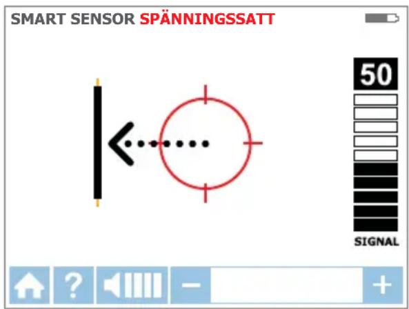
text_image
SMART SENSOR SPÄNNINGSSATT 50 SIGNALtext_image
SMART SENSOR SPÄNNINGSSATT 75 SIGNALnatural_image
Diagram of a power plug with circular ports and a black cable, showing rotational direction (no text or symbols)text_image
Diagram showing electrical connections with a power outlet, wires, and a device labeled with symbols like 'No' and prohibition symbol.natural_image
Diagram of a device with three colored wires (green, red, green) connecting a terminal block to an electrical outlet (no text or symbols present)text_image
L N PE TP SENSOR DIMENSIONS 75 10-400 Hz TP SENSOR PROCESSED 36-400V AC/DC 40-400 Hz 0 0 0 0 0 0natural_image
Illustration of a red handheld electronic device with four square buttons and a screen, mounted on a wall (no text or symbols visible)text_image
Diagram illustrating a sensor-based electrical circuit with connected components and a digital display showing top sensor energyized level.text_image
Diagram showing electrical connections between a cylindrical device and a multimeter, with labeled components and wiring paths.text_image
Diagram showing electrical connections between a device and a mobile phone, with labeled components and wiring paths.natural_image
Diagram of a plug electrical socket with circular arrows indicating clockwise rotation (no text or symbols)6. TEKNISET TIEDOT 35
Yleistä
text_image
Diagram illustrating cable connection and wire routing with labeled components and wiring diagramstext_image
Diagram illustrating a multi-wire electrical circuit with sensor connections and component diagrams, showing wiring and grounding.text_image
L N PE 0 0 0 0 0 0 0 0 0 0 0 0 0 0 0 0 0 0 0 0 0 0 0 0 0 0 0 0 0 0 0 0 0 0 0 0 0 0 0 0 0 0 0 75 OK ✓ OKtext_image
Diagram showing two electrical outlets connected to a device with labeled wires and a warning symbolnatural_image
Diagram of a plug electrical socket with circular arrows indicating clockwise rotation (no text or symbols)text_image
Diagram showing electrical connections with a power outlet, wires, and a device labeled '2018.2'natural_image
Diagram of a device with three colored wires (green, red, green) connecting a circular component to an electronic device (no text or symbols visible)natural_image
Illustration of a red and gray handheld payment terminal with four digital display panels above it (no text or symbols)text_image
Diagram illustrating a multi-winding electrical circuit with a sensor, motor, and terminal connections, including a 75% AC/DC display.text_image
Diagram showing electrical connections between a cylindrical device and a multimeter, with labeled components and wiring paths.text_image
Diagram showing electrical connections between a device and a mobile phone, with labeled components and wiring paths.natural_image
Diagram of a plug electrical socket with circular arrows indicating clockwise rotation (no text or symbols)PARISTOKYNNYS ALKALI
NR6 6JB United Kingdom
Telephone:
+44 (0) 1603 25 6662
beha-amprobe.com
Holanda - Sede**
Science Park Eindhoven 5110
5692 EC Son
Holanda
Telephone:
+31 (0) 40 267 51 00
beha-amprobe.com
text_image
Diagram illustrating a cable connection and sensor setup with labeled components and wiring connectionstext_image
Diagram illustrating cable connection and wiring with labeled components and wiring configurationsflowchart
graph LR
    A["L"] --> B["RCD"]
    C["N"] --> B
    B --> D["Gate 1"]
    D --> E["Gate 2"]
    E --> F["Gate 3"]
    F --> G["Gate 4"]
    G --> H["Ground"]
    I["PE"] --> J["Ground"]
    K["Ground"] --> L["Ground"]
    M["Ground"] --> N["Ground"]
    O["Ground"] --> P["Ground"]
    Q["Ground"] --> R["Ground"]
    S["Ground"] --> T["Ground"]
    U["Ground"] --> V["Ground"]
    W["Ground"] --> X["Ground"]
    Y["Ground"] --> Z["Ground"]
    AA["Ground"] --> AB["Ground"]
    AC["Ground"] --> AD["Ground"]
    AE["Ground"] --> AF["Ground"]
    AG["Ground"] --> AH["Ground"]
    AI["Ground"] --> AJ["Ground"]
    AK["Ground"] --> AL["Ground"]
    AM["Ground"] --> AN["Ground"]
    AO["Ground"] --> AP["Ground"]
    AQ["Ground"] --> AR["Ground"]
    AS["Ground"] --> AT["Ground"]
    AU["Ground"] --> AV["Ground"]
    AW["Ground"] --> AX["Ground"]
    AY["PE"] --> AZ["Ground"]
text_image
Diagram showing connections between two electrical outlets connected to a device with a fault symbol and power rating indicator.text_image
L N PE TP SENSOR ENRIGISED 75 0 30-480V AC/DC 46.480 Hz TP SENSOR ENRIGISED 30-480V AC/DC 46.480 Hztext_image
SMART SENSOR COM TENSÃO 0 SIGNALtext_image
SMART SENSOR COM TENSÃO 50 SIGNALFigura 3.1e: Cabo à esquerda
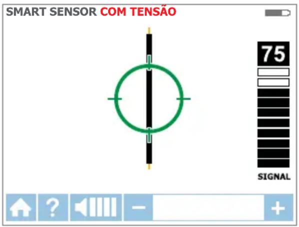
text_image
SMART SENSOR COM TENSÃO 75 SIGNALnatural_image
Diagram of a power plug with circular arrows indicating clockwise rotation (no text or symbols)text_image
Diagram showing electrical connections with a power outlet, green cable, and a device labeled '2023-1' with a prohibition symbol.natural_image
Diagram of a device with three colored wires (green, red, green) connecting a terminal block to an electrical outlet (no text or symbols present)natural_image
Illustration of a red handheld payment terminal with four digital display panels above it (no text or symbols)Figura 3.3e: Alinhamento correto do Sensor de Ponta no disjuntor
text_image
Diagram illustrating a medical or electrical setup with labeled components and a tip sensor visualization showing 75% signal.text_image
Diagram of a mechanical or electrical testing setup with labeled components and wiring connectionstext_image
Diagram showing electrical connections between a device and a mobile phone, with labeled components and wiring paths.natural_image
Diagram of a plug electrical socket with circular arrows indicating rotation (no text or symbols)Trocar as pilhas do Transmissor
Figura 5.1a: Trocar as pilhas do transmissor
Seleccionar manualmente o tipo de pilhas do transmissor
Trocar as pilhas do Recetor
Figura 5.1b: Trocar as pilhas do recetor
2. SETTETS DELER....5
2.1 AT-8000-RE-mottaker 6
2.2 AT-8000-TE-sender 8
2.3 CT-400-EUR signalklemme....11
3. HOVEDSAKELIGE BRUKSOMRÅDER.... 12
5. VEDLIKEHOLD....31
text_image
Diagram illustrating cable connection and waveform analysis with labeled components and wiring pathstext_image
Diagram illustrating a cable connection and scanning process with labeled components and wiring diagramsFigur 2.2b: Genererer et signal i Sløyfe-modus
Obs: Sløyfemodus fungerer kun på strømløse kretser. Det deaktiveres automatisk när senderen er koblet til strømførende linje med prøveledninger.
text_image
Diagram showing two electrical outlets connected to a device with colored wires and a red lightning bolt symbol indicating the connection.natural_image
Diagram of a plug electrical socket with circular ports and a shaft, showing clockwise rotation arrows (no text or symbols)text_image
Diagram showing electrical connections with a power outlet, wire, and a device labeled with a prohibition symbolnatural_image
Diagram of a device with three colored wires (green, red, green) connecting to a circular component, no text or symbols present.Figur 3.3a: Forenklet direkte forbindelse
natural_image
Illustration of a red handheld payment terminal with four digital display panels mounted on a wall (no text or symbols)text_image
Diagram illustrating a sensor setup with connected components and a 75% signal detection interface.Figur 4.6a: Spore en skjermet ledning
Hvis skjermet ledning er koblet fra jording på den andre enden:
- Sett opp senderen i ledningssporingsmodus. (Se avsnitt 3.2.)
- Koble fra jordingen på den skjermede ledningen, og koble skjermen til en av Senderens klemmer (polaritet spiller ingen rolle) med en prøveledning.
-
Koble senderens andre utgang til en egen jording.
-
Still mottakeren til ledningssporingsmodus for å spore skjermen, som beskrevet i avsnitt 3.2.
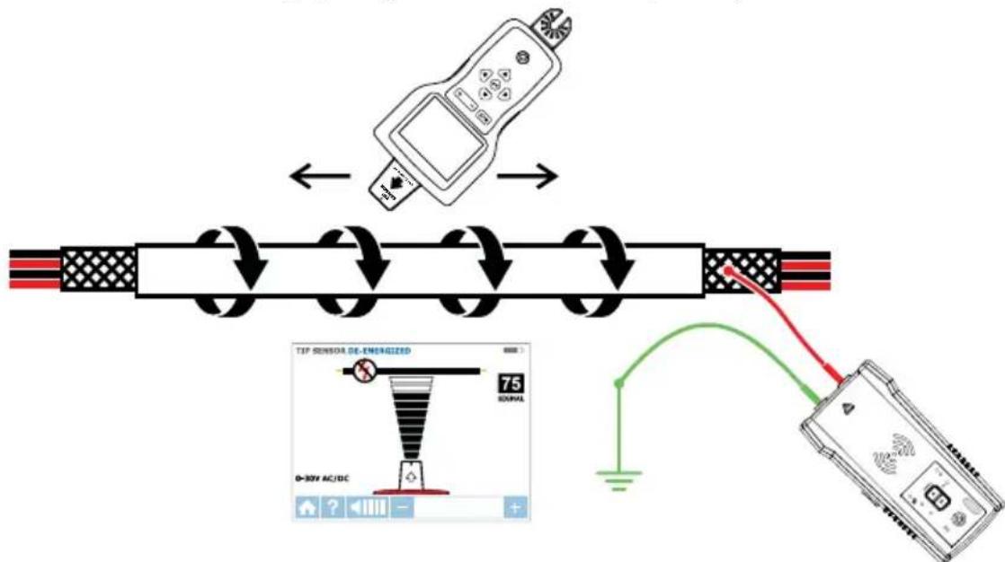
flowchart
graph TD
    A["Input Sensor"] --> B["Thermal Setup"]
    B --> C["Electric Resistor"]
    C --> D["Output Display"]
    D --> E["Analog Device"]
Figur 4.6b: Spore en skjermet ledning frakoblet jord på den andre enden
text_image
Diagram showing electrical connections between a cylindrical device and a multimeter, with labeled components and wiring paths.text_image
Diagram showing electrical connections between a device and a mobile phone, with labeled components and wiring paths.natural_image
Diagram of a plug electrical socket with circular arrows indicating rotation (no text or symbols)Figur 4.12d: Roter mottakeren for å være på linje med ledningen
text_image
SETTINGS Language: English Backlight: Settings: ✓ DEFAULT OFF Help Guidance: ✓ ON OFF Sensitivity: ✓ MAN AUTO Smart Sensor Range: ✓ SHORT LONG VERSION FWD: 2.8.6 HWD: 1.7 Startmenutext_image
Diagram illustrating cable connection and waveform analysis with labeled components and wiring pathstext_image
Diagram illustrating cable connection and wiring setup with labeled components and wiring diagramsFig 2.2b: Genererer et signal i LOOP-tilstand
text_image
Diagram showing two electrical outlets connected to a device with labeled wires and a warning symbolFig. 3.1a: Korrekt forbindelse med separat neutral
natural_image
Diagram of a power plug with circular arrows indicating clockwise rotation (no text or symbols)text_image
Diagram showing electrical connections with a power outlet, wires, and a device labeled 'V-100' and a prohibition symbol.natural_image
Diagram of a device with three colored wires (green, red, green) connecting a circular component to an electronic device (no text or symbols visible)Fig. 3.3a: Forenklet direkte forbindelse
natural_image
Illustration of a red and gray payment terminal device with four digital display panels above it (no text or symbols)text_image
Diagram illustrating a sensor setup with connected components and a top sensor calibration screen showing voltage range.text_image
Diagram of a measurement setup with labeled components and wiring connectionstext_image
Diagram showing electrical connections with labeled components and wiring paths, including a multimeter and a digital device.natural_image
Diagram of a plug with circular ports and a cable, showing clockwise rotation arrows (no text or symbols)NR6 6JB United Kingdom
Telefon:
+44 (0) 1603 25 6662
beha-amprobe.com
text_image
Diagram illustrating cable connection and wiring setup with labeled components and wiring diagramstext_image
Diagram illustrating a cable connection and waveform analysis setup with labeled components and wiring pathstext_image
L N PE C O Q C O Q C O Q C O Q C O Q C O Q C O Q C O Q C O Q C O Q C O Q C O Q C O Q C O Q C O Q C O Q C O Q C N N N N N N N N N N N N N N N N N N N N N N N N N N N N N N N N N N N N N N N N N N N N N N N N N N O140000000000000000000000000000000000000000000000000000000000000000000000000000000000000000000000000000text_image
Diagram showing connections between two electrical outlets connected to a multimeter with a fault symbol indicated.natural_image
Diagram of a plug electrical socket with circular arrows indicating clockwise rotation (no text or symbols)text_image
Diagram showing electrical connections with a power outlet, wire, and no-smoking symbolnatural_image
Diagram of a device with three colored wires (green, red, yellow) connecting a circular component to an electronic device (no text or symbols visible)natural_image
Illustration of a red handheld payment terminal with four digital display panels above it (no text or symbols)text_image
Diagram illustrating a sensor setup with connected devices and a digital display showing 75 microcontroller temperature reading.text_image
Diagram showing electrical connections between a cylindrical device and a multimeter, with labeled components and wiring paths.text_image
Diagram showing electrical connections between a device and a handheld device, with labeled components and wiring paths.natural_image
Diagram of a plug electrical socket with circular arrows indicating rotation (no text or symbols)- Catalog
- Application notes
• Product specifications - User manuals