Cool 9 Connected - Air Conditioning WILFA - Free user manual and instructions
Find the device manual for free Cool 9 Connected WILFA in PDF.
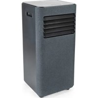
| Product type | Mobile monobloc air conditioner |
| Brand | Wilfa |
| Model | Cool 9 Connected |
| Refrigerant | R290 (flammable gas) |
| Minimum room area | 11 m² |
| Operating temperature range | 16 °C to 35 °C |
| Operating modes | Cooling, Dehumidification, Fan, Auto |
| Control | Control panel and remote control |
| Connectivity | Built-in Wi-Fi |
| Timer | Yes (0.5 to 24 hours) |
| Air filter | Washable, clean every 3 months |
| Remote control | Included (AAA batteries 2×1.5 V) |
| Heat exhaust hose | Length less than 1 m |
| Drainage | Via lower opening or continuous with hose |
| Power supply | 230 V ~ 50 Hz |
| Warranty | 5 years |
| Safety | Automatic shut-off in case of anomaly, overheat protection |
| Cleaning | Exterior casing with soft cloth, filter with water |
| Spare parts | Filter, remote control, exhaust hose |
| Supplied accessories | Seal, clips, hose clamp, plug, drain connector, remote control, batteries, user manual |
Frequently Asked Questions - Cool 9 Connected WILFA
User questions about Cool 9 Connected WILFA
0 question about this device. Answer the ones you know or ask your own.
Ask a new question about this device
Download the instructions for your Air Conditioning in PDF format for free! Find your manual Cool 9 Connected - WILFA and take your electronic device back in hand. On this page are published all the documents necessary for the use of your device. Cool 9 Connected by WILFA.
USER MANUAL Cool 9 Connected WILFA
natural_image
White portable air conditioner unit with cooling fins and control panel (no visible text or symbols)COOL 9 CONNECTED
AIR CONDITIONER
EN · Instruction manual
NO · Bruksanvisning
SE · Bruksanvisning
INSTRUCTION MANUAL · AIR CONDITIONER
CONTENTS
4 IMPORTANT SAFETY INSTRUCTIONS
6 EXCEPTION CLAUSES
7 THE REFRIGERANT
9 OPERATION ENVIROMENT
12 PRODUCT OVERVIEW – MAIN UNIT
14 PRODUCT OVERVIEW - CONTROL PANEL
16 PRODUCT OVERVIEW – REMOTE CONTROL
17 PRODUCT OVERVIEW – REMOTE CONTROL DISPLAY
19 REPLACEMENT OF BATTERIES
20 CLEANING AND MAINTENANCE
21 CHECKS
21 LONG-TIME STORAGE
21 NOTICE FOR RECOVERY
22 TROUBLESHOOTING
24 ERROR CODE
25 INSTALLATION
32 GUARANTEE
33 PRODUCT SPECIFICATIONS
33 SUPPORT AND SPARE PARTS
33 RECYCLABILITY
EN
IMPORTANT SAFETY INSTRUCTIONS
- Read this instruction manual thoroughly before use and save it for future reference. It is also available at our website; wilfa.com.
- This appliance can be used by children aged from 8 years and above and persons with reduced physical, sensory or mental capabilities or lack of experience and knowledge if they have been given supervision or instruction concerning use of the appliance in a safe way and understand the hazards involved.
- Cleaning and user maintenance shall not be made by children without supervision. Children shall not play with the appliance.
- Before operation, please confirm whether power specification complies with that on nameplate.
- Before cleaning or maintaining the air conditioner, please turn off air conditioner and pull out the power plug.
- Make sure the power cord hasn't been pressed by hard objects.
- Do not pull or drag the power cord to pull out the power plug or move the air conditioner.
- Do not insert or pull out the power plug with wet hands.
- Please use the grounded power. Make sure the grounding is reliable.
- If the supply cord is damaged, it must be replaced by the manufacturer or its service agent or a similarly qualified person in order to avoid a hazard.
- If abnormal condition occurs (e.g. burned smell), please disconnect power at once and then contact local dealer.
- When nobody is taking care of the unit, please turn it off and remove the power plug or disconnect power.
- Do not splash or pour water on air conditioner. Otherwise, it may cause short circuit or damage to air conditioner.
- If drainage hose is used, ambient temperature can't be lower than 0^ . Otherwise, it will cause water leakage to air conditioner.
- Prohibit operating heating equipment around the air conditioner.
- Prohibit operating the unit in the bathroom or laundry room.
- Far away from fire source, inflammable and explosive objects.
EN
- Children and disabled people are not allowed to use the unit without supervision.
- Keep children from playing or climbing on the air conditioner.
- Do not put or hang dripping objects above the air conditioner.
- Do not repair or disassemble the air conditioner by yourself.
- Prohibit inserting any objects into the air conditioner.
- Do not use an extension cord.
- Do not put sundries into the air duct. If sundries get into the air duct, please contact the professionals to deal with it.
EXCEPTION CLAUSES
Supplier will bear no responsibilities when personal injury or property loss is caused by the following reasons:
- Damage the product due to improper use or misuse of the product.
-
Alter, change, maintain or use the product with other equipment without abiding by the instruction manual of manufacturer.
-
After verification, the defect of product is directly caused by corrosive gas.
- After verification, defects are due to improper operation during transportation of product.
- Operate, repair, maintain the unit without abiding by instruction manual or related regulations.
- After verification, the problem or dispute is caused by the quality specification or performance of parts and components that produced by other manufacturers.
- The damage is caused by natural calamities, bad using environment or force majeure.
Appliance filled with flammable gas R290.

before installing and using the appliance, read the manual first.
THE REFRIGERANT
- To realize the function of the air conditioner unit, a special refrigerant circulates in the system. The used refrigerant is the fluoride R290, which is specially cleaned.
EN
- The refrigerant is flammable and inodorous. Furthermore, it can lead to explosion under certain conditions.
- Compared to common refrigerants, R290 is a non-polluting refrigerant with no harm to the ozonosphere. The influence upon the greenhouse effect is also lower. R290 has got very good thermodynamic features which lead to a high energy efficiency. The units therefore need a less filling.
- Please refer to the nameplate for the charging quantity of R290.
WARNING
- Appliance filled with flammable gas R290.
- Appliance shall be installed, operated and stored in a room with a floor area larger than 11m^2 .
- The appliance shall be stored in a room without continuously operating ignition sources (for example: open flames, an operating gas appliance or an operating electric heater.)
- The appliance shall be stored in a well-ventilated area where the room size corresponds to the room area as specified for operation.
-
The appliance shall be stored to prevent mechanical damage from occurring.
-
Ducts connected to an appliance shall not contain an ignition source.
- Keep any required ventilation openings clear of obstruction.
- Do not pierce or burn.
- Be aware that refrigerants may not contain an odour.
- Do not use means to accelerate the defrosting processorto clean, other than those recommended by the manufacturer.
- Servicings shall be performed only as recommended by the manufacturer.
- Should repair be necessary, contact your nearest authorized Service Centre.
- Any repairs carried out by unqualified personnel may be dangerous.
- Compliance with national gas regulations shall be observed.
- The air conditioner must be operated within the temperature range: 16^ C \~ 35^ C.
- The appliance is for indoor use only.
EN
- The appliance must be positioned so that the plug is accessible.
- This air conditioner is for domestic, non-commercial use only.
- Reserved space around the air conditioner should be 30cm at least.
- Do not operate the air conditioner at humid environment.
- Please keep air inlet and air outlet clean, no obstacles.
- During operation, close doors and windows to improve cooling effect.
- Please put the air conditioner at smooth and flat ground for operation to avoid noise and vibration.
- This air conditioner is equipped with castors. Castors should slide at smooth and flat ground.
- Prohibit inclining or turning over the air conditioner. If there's abnormality, please disconnect power immediately and contact dealer.
- Avoid direct sunshine.
text_image
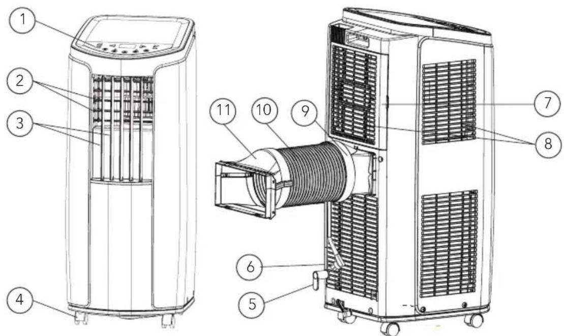
ENPRODUCT OVERVIEW – MAIN UNIT
text_image
Technical diagram of an air conditioner unit with numbered components for identification- Controller panel
- Horizontal louver
- Vertical louver
- Castor
- Wire-fixing hook
- Plug of power cord
-
Filter
-
Air inlet
- Joint
- Heat discharge pipe
- Rear clip
USE
To change air direction:
-
Up/Down air flow direction:
-
Hold the horizontal louvers and adjust the air flow directions.
-
Do not adjust the horizontal louvers to the lowest or the highest position in the COOL or DRY mode with the fan speed set too low for an extended period of time, Condensation may form on the louvers.
-
Left/right air flow direction. Hold the vertical louver and adjust the air flow direction.
Caution:
- Do not adjust the vertical louvers to the extreme left or right in the COOL or DRY mode with the fan speed set too low for an extended period. Condensation may form on the louvers.
OPERATION TEST
- Press on/off button on the remote controller to start the unit.
- Press mode button to select auto, cooling, drying or fan function, and check if the unit operates normally.
- If ambient temperature is below 16^ C the unit cannot operate in cooling mode.
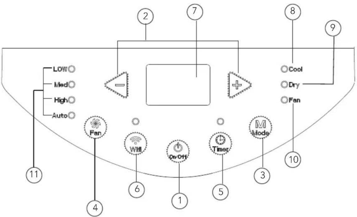
PRODUCT OVERVIEW - CONTROL PANEL
flowchart
graph TD
    A["11"] --> B["LOW"]
    A --> C["Med"]
    A --> D["High"]
    A --> E["Auto"]
    B --> F["Fan"]
    C --> G["Wi-Fi"]
    D --> H["On-Off"]
    E --> I["Timer"]
    F --> J["2"]
    G --> K["6"]
    H --> L["1"]
    I --> M["5"]
    J --> N["7"]
    K --> O["8"]
    L --> P["3"]
    M --> Q["10"]
    N --> R["9"]
    O --> S["Cool"]
    P --> T["Dry"]
    Q --> U["Fan"]
- ON/OFF button
- +/- button
- Mode button
- Fan button
- Timer button
- Wi-fi button
-
Display
-
Cool mode indicator
- Dry mode indicator
- Fan mode indicator
- Fan speed indicator
USE
• After connecting the air conditioner to the power supply, it will sound a beep. After that, you can operate the air conditioner by the control panel.
- Under ON status, after each pressing of the button on control panel, the air conditioner will give out a sound. Meanwhile, corresponding indicator on control panel will be bright.
① ON/OFF button
Pressing this button will turn on or turn off the air conditioner.
② +/- button
Under cooling mode, press "+" or "-" button to increase or decrease the temperature by 1°C (°F). Set temperature range is 16°C\~30°C Under drying or fan mode, this button is invalid.
③ Mode button
Press this button and the mode will circulate according to below sequence: Cool-> Dry-> Fan
- Cool: Under this mode, cooling mode indicator is bright. The display shows set temperature. Temperature setting range is 16-30 degrees Celsius.
- Dry: Under this mode, drying mode indicator is bright.
- Fan: Under this mode, the air conditioner only blow fan. Fan indicator is bright.
④ Fan button
Press this button and the fan speed will circulate as "low speed-medium speed-high speed-auto fan-low speed"
⑤ Timer button
- Press timer button to enter timer setting mode.
- Under this mode, press " + " or " - " button to adjust the timer.
- The timer will increase or decrease 0.5 hour by pressing “+” or “-” within 10 hours.
Exceeding 10 hours, the timer will increase or decrease 1 hour when pressing "+" or "-" . After setting the timer, the display shows the temperature if there's no operation for 5s. If timer function is started up, the upper indicator will keep the display status. Under timer mode, press timer button again to cancel timer mode.
⑥ Wi-fi button
- Press "WiFi" button to turn on WiFi function, "WiFi" icon will be displayed on the remote controller: Hold "WiFi" button for 5s to turn off WiFi function and "WiFi" icon will disappear.
- Under off status, press "MODE" and "WiFi" buttons simultaneously for 1s, WiFi module will restore factory settings.
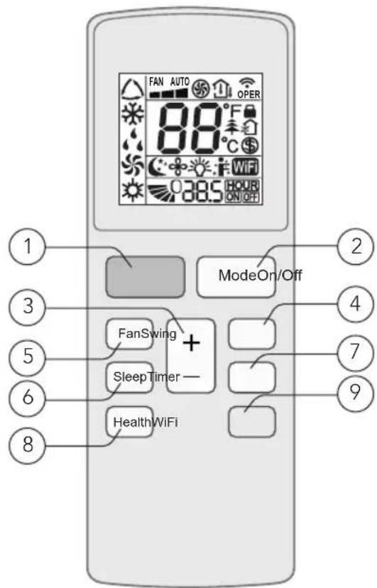
PRODUCT OVERVIEW – REMOTE CONTROL
text_image
FAN AUTO OPER 88°C 38.5 HOUR ON/OFF ModeOn/Off FanSwing + SleepTimer - HealthWiFi 1 2 3 4 5 6 7 9 8- ON/OFF button
- Mode button
- +/- button
- Swing button (not available)
- Fan button
-
Sleep button
-
Timer button
- Health button (not available)
- WiFi button
PRODUCT OVERVIEW – REMOTE CONTROL DISPLAY
EN
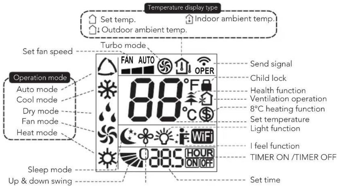
text_image
Temperature display type Set temp. Indoor ambient temp. Outdoor ambient temp. Set fan speed Turbo mode Operation mode Auto mode Cool mode Dry mode Fan mode Heat mode Sleep mode Up & down swing FAN AUTO OPER 80°F 80°C 305 HOUR ON OFF Send signal Child lock Health function Ventilation operation 8°C heating function Set temperature Light function I feel function TIMER ON /TIMER OFF Set timeNOTE:
This is a general use remote controller, and some functions, as described are non-functioning.
USE
① ON/OFF button
Press this button to turn on the unit. Press this button again to turn off the unit.
② Mode button
Press this button and the mode will circulate according to below sequence: Auto -> Cool -> Dry-> Fan-> Heat
- Auto: During auto the unit will automatically adjust the settings. The set temperature cannot be changed.
- Cool: Under this mode, air conditioner operates under cooling mode. Cooling indicator will be on. Press "Fan Speed" button to adjust the fan speed.
- Dry: Under this mode, the unit runs in low fan speed for dehumidification and the corresponding indicator is on. The fan speed cannot be adjusted.
- Fan: Under this mode, air conditioner will not cool or heat, only blow wind. Fan indicator will be on. Press "Fan Speed" button to adjust the fan speed.
- Heat: Not available
③ +/- button
- Pressing "+" or "-" button once will increase or decrease set temperature by 1°C (°F). Hold "+" or "-" button for 2s, set temperature on remote controller will change quickly.
- Release the button after your required set temperature is reached.
Under timer setting status, after each pressing of "+" or "-" button, time will increase or decrease 0.5h. Hold "+" or "-" button and the time on the display will change quickly.
④ Swing button
Not available for this unit.
⑤ Fan button
This button sets the fan speed. The sequence goes from auto, 1, 2, 3, and back to auto.
⑥ Sleep button
Press this button to turn the sleep mode on. This function maintains the most comfortable temperature for you.
⑦ Timer button
- Press this button once and the characters of HOUR ON (OFF) will flash.
- Meanwhile, press "+" button or "-" button to adjust timer setting (time will change quickly if holding "+" or "-" button). Time range is 0.5\~24 hours.
- Press this button again to confirm timer setting and the characters of HOUR ON (OFF) will stop flashing.
If the characters are flashing but you haven't press timer button, timer setting status will be stopped after 5s. If timer is confirmed, press this button again to cancel timer.
⑧ Health button
Not available for this unit.
⑨ Wi-fi button
- Press "WiFi" button to turn on WiFi function, "WiFi" icon will be displayed on the remote controller: Hold "WiFi" button for 5s to turn off WiFi function and "WiFi" icon will disappear.
- Under off status, press "MODE" and "WiFi" buttons simultaneously for 1s, WiFi module will restore factory settings.
Combination of buttons:
- Temperature display switchover function: Under OFF status, press "-" and "Mode" buttons simultaneously to switch temperature display between °C and °F.
- Light function: Under switch-on or switch-off state, you may hold "+" and "FAN" buttons simultaneously to set the lamp on or off and send the code. After being energized the lamp is defaulted on.
REPLACEMENT OF BATTERIES
- Press the back side of remote controller on the spot marked with 📄 and push the cover of the battery box along the arrow direction.
- Replace two (AAA 1.5V) dry batteries, and make sure the positions of + and - are correct.
- Reinstall the cover of the battery box.
Note:
- During operation, point the remote-control signal sender at the receiving window on unit.
- The distance between signal sender and receiving window should be no more than 8m, and there should be no obstacles between them.
- Signal may be interfered easily in the room where there is fluorescent lamp or wireless telephone; remote controller should be close to the unit during operation.
- Replace new batteries of the same model when replacement is required.
- When you don't use remote controller for a long time, please take out the batteries.
- If the display on remote controller is fuzzy or there's no display, please replace batteries.
EN
CLEANING AND MAINTENANCE
Warning:
- Before cleaning the air conditioner, please turn off the unit and disconnect power. Otherwise, it may cause electric shock.
- Do not wash air conditioner with water. It may cause electric shock.
- Do not use volatile liquid (such as thinner or gas) to clean the air conditioner. Otherwise, it may damage the appearance of air conditioner.
- Do not splash water or any other liquid into it, it may damage the plastic components, even cause electric shock.
CLEAN OUTER CASE
If there is dust on the surface of outer case, please use soft towel to wipe it. If the outer case is very dirty (such as grease), please use neutral abluent to wipe it.
CLEAN GRILLE
Use cleaner or soft brush to clean it.
CLEAN FILTER
-
Remove the filter.
-
Press the clasp, and then remove the filter 1.
– Pull out the filter 2. -
Clean filter
- Use cleaner or water to clean the filter. If the filter is very dirty (such as grease), use warm water 40^ (104°F) mixed with neutral detergent to clean it and then put at shady place to dry it.
- Install the filter.
- After the filter is cleaned and dried, reinstall it correctly.
Note:
- The filter should be cleaned about once every three months. If there's much dust in the operation environment, you can increase clean frequency.
- Do not dry the filter with fire or hair drier. Otherwise, it may be deformed or catch fire.
CLEAN HEAT DISCHARGE PIPE
Remove the heat discharge pipe from air conditioner, clean and dry it, and then reinstall it. (For the method of installation and removal, please refer to the instruction for "installation and disassembly of heat discharge pipe").
CHECKS
CHECKING BEFORE USE
- Check whether air inlets and air outlets are blocked.
- Check whether plug and socket are in good condition.
- Check whether filter is clean.
- Check whether batteries are installed in remote controller.
- Check whether joint, window bracket and heat discharge pipe are installed tightly.
- Check whether heat discharge pipe is damaged.
CHECK AFTER USE
- Disconnect power supply.
- Clean filter and outer case.
- Remove dust and other impurities from the air conditioner.
- Eliminate accumulated water in chassis (refer to the section of "drainage way" for details).
- Check whether window bracket is damaged or not. If yes, please contact dealer.
LONG-TIME STORAGE
If you don't use the air conditioner for a long time, please maintain it by following steps for good performance:
- Make sure there's no accumulated water in chassis and that the heat discharge pipe is disassembled.
- Pull out the plug and wrap the power cord.
- Clean the air conditioner and pack it well to prevent dust.
NOTICE FOR RECOVERY
- Parts of gift packaging is recycled. Users are advised to follow local regulations or take contact with personnel at the local recycling centre for further guidance.
- If you want to throw away the air conditioner, please contact local division or consultant service centre for the correct disposal method.
TROUBLESHOOTING
Please check below items before asking for maintenance. If the malfunction still can't be eliminated, please contact local dealer or qualified professionals.
| Problem Possible reasons Solutions | ||
| Air conditioner can't operate | Power failure | Wait after power recover |
| Is the plug loose? | Reinsert the plug | |
| Has the air switch tripped off or has the fuse been blown? | Ask for professional help to replace air switch or fuse. | |
| Is there's malfunction for the circuit? | Ask for professional help to replace circuit. | |
| Has the unit been restarted immediately after a stop? | Wait for 3 min, and then try turning it on again. | |
| Poor cooling Is the power too low? | Make sure that the device has been connected to a proper power source. | |
| Air conditioner can't receive signal from remote controller or remote controller is not sensible. | Is normal operation interrupted by events such as static pressure, unstable voltage? | Please pull out the plug. Insert the plug after about 3min, and then turn on the unit. |
| Is the remote controller within the receiving range? | The receiving range of remote controller is 8m. Do not exceed this range. | |
| Does any physical obstacles block free sight between remote and unit? | Remove the obstacles. | |
| Is sensitivity of remote controller low? | Check the batteries of remote controller. If the power is low, please replace the batteries. | |
| Is there a fluorescence lamp in the room? | Move the remote controller close to air conditioner.Turn off the fluorescence lamp and try it again. | |
| No fan blown out from air conditioner. | Is the air outlet or inlet blocked? | Eliminate the obstacles. |
| Is the filter dirty? | Clean the filters. | |
| Set temperature can't be adjusted. | Has the unit been set to auto mode or has child lock been activated? | Temperature can't be adjusted under auto mode. Child lock can be unlocked by pressing "+" and "-" . |
| Is the room temperature within the temperature range for the unit? | Temperature setting range: 16°C-30°C. | |
| There is off flavour. | There's off flavour source in the room, such as furniture, cigarette etc. | Remove the off flavour source.Clean the filter. |
| There's abnormal sound during Operation. | Were the unit interfered by thunder, radio, etc? | Disconnect the power, put the power on again, then turn on the unit. |
| You can hear water-flowing sound. | Were the unit just turned on or off? | There is a sound of the refrigerant inside the unit. This is normal. |
| It sounds like something is breaking. | Were the unit just turned on or off? | Heat expansion or shrinkage for the panel due to change of temperature can cause friction sound. This is normal. |
ERROR CODE
Error code Troubleshooting
F0, F1, F2, F4 Please contact our service-centre.
E8, H3 1. Check if the unit is in a high-temperature and high-humidity Environment. If ambient temperature is too high, power off the unit and then energize it for operation after the ambient temperature drops to 35^(95^) below.
2. Check if the evaporator and condenser are blocked by some objects; if yes, take away the objects, power off the unit and then energize it for operation.
3. If the malfunction still occurs, please contact our service-centre.
H8 1. Pour the water inside the chassis out.
- If H8 still occurs, please contact our service-centre.
Warning:
- If there are following phenomenon, please turn off the air conditioner and disconnect the power immediately, and then contact dealer immediately.
– Power cord is overheating or damaged. - Abnormal sound during operation.
- Off-flavor.
- Water leakage.
- Do not repair or refit the air conditioner by yourself.
- If operate the air conditioner! under abnormal condition, it may cause malfunction, electric shock or fire hazard.
INSTALLATION
PRECAUTIONS
Warning:
- Observe all governing codes and ordinances.
- Do not use damaged or non-standard power cord.
- Be careful during installation and maintenance. Prohibit incorrect operation to prevent electric shock, casualty and other accidents.
SELECTION OF INSTALLATION LOCATION – BASIC REQUIREMENTS
Installing the unit in the following places may cause malfunction. If it is unavoidable, please consult the local dealer:
- The place with strong heat sources, vapours, flammable, or explosive gas, or volatile objects spread in the air.
- The place with high-frequency devices (such as welding machine, medical equipment).
- The place near coast area.
- The place with oil or fumes in the air.
- The place with sulfureted gas.
- Other places with special circumstances.
- It's not allowed to be installed on the unstable or motive base structure (such as truck) or in the corrosive environment (such as chemical factory).
REQUIREMENT OF AIR CONDITIONER
- Air inlet should be far away from obstacles and do not put any objects near air outlet. Otherwise, it will affect the radiation of heat discharge pipe.
- Please try your best to keep far away from fluorescent lamp.
- The appliance shall not be installed in the laundry. High humidity can cause malfunction.
REQUIREMENTS FOR ELECTRIC CONNECTION
Safety precautions:
- Must follow the electric safety regulations when installing the unit.
- According to the local safety regulations, use qualified power supply circuit.
- If the supply cord is damaged, it must be replaced by the manufacturer, its service agent or similarly qualified persons in order to avoid a hazard.
- Properly connect the live wire, neutral wire and grounding wire of power socket.
- Be sure to cut off the power supply before proceeding any work related to electricity and safety.
EN
INSTRUCTION MANUAL · AIR CONDITIONER
-
Do not put through the power before finishing installation.
-
The air conditioner is first class electric appliance. It must be properly grounding with specialized grounding device by a professional. Please make sure it is always grounded effectively, otherwise it may cause electric shock.
-
The grounding resistance should comply with national electric safety regulations.
-
The appliance shall be installed in accordance with national wiring regulations.
-
The yellow-green wire or green wire in the airconditioner is a grounding wire, which can't be used for other purposes.
PREPARATION BEFORE INSTALLATION
Note: Check if the accessories are available before installation.
Accessory list
 Joint A Heat discharge pipe Rear clip Wire hook Joint A Heat discharge pipe Rear clip Wire hook |  |  | 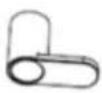 |
 Pipe clip Screw Drainage pipe Rubber plug Pipe clip Screw Drainage pipe Rubber plug | [08AD] | 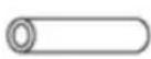 |  |
 Drain connector Remote control Battery (AAA 1.5V) User manual Drain connector Remote control Battery (AAA 1.5V) User manual | 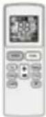 |  |  |
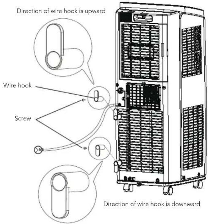
INSTALL WIRE HOOK
- Assemble the wire hook at the back of the unit with screws (the direction of wire hook is as shown in following figure)
text_image
Direction of wire hook is upward Wire hook Screw Direction of wire hook is downward• Wind the power cord around the wire hook
natural_image
Technical line drawing of a dual-chamber industrial air conditioning unit with cooling fans and wheels (no text or symbols)EN
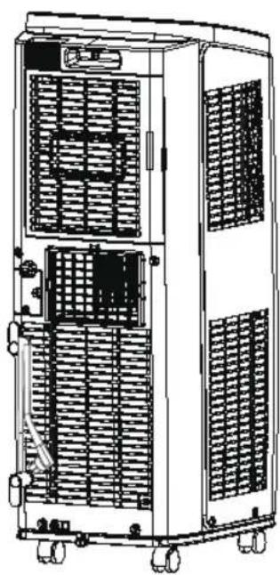
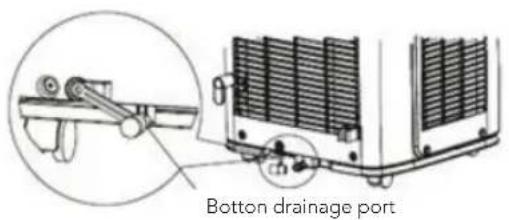
REMOVING COLLECTED WATER
When using the bottom drainage port to drain water, install the drainage pipe before use. Poor drainage will affect normal operation of the unit.
Instruction for drainage pipe installation as follows:
- Fix the drainage pipe clip on the right of rear side plate near drainage port with a screw.
text_image
Bottom drainage port Screw Drainage pipe clip- Remove the rubber plug from the bottom drainage port.
text_image
Bottom drainage port-
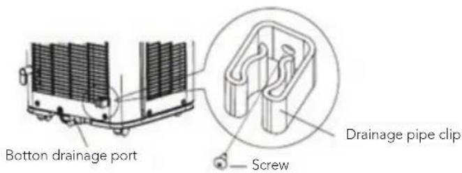
Put the drainage pipe into the bottom drainage port and screw it in.
-
Put the rubber plug into the other side of the drainage pipe, then fix it in the drainage pipe clip.
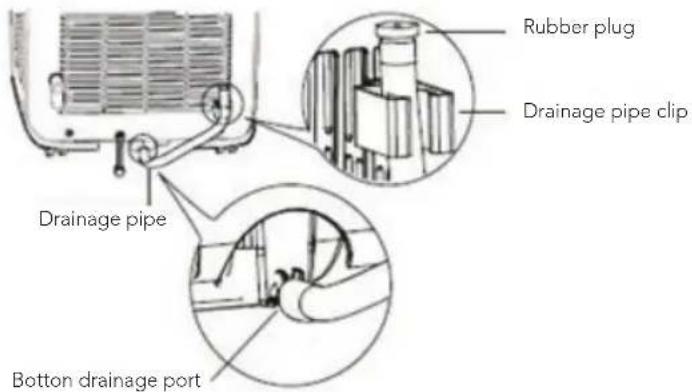
text_image
Rubber plug Drainage pipe clip Drainage pipe Bottom drainage portEN
DRAINAGE METHOD
- Drainwater from the bottom drainage port
- Turn the unit off, and pull the plug from the socket.
- Place a water container under the bottom drainage port, or move the unit to a place where it can drain.
- Remove the rubber plug of the bottom drainage port to drain water.
- After draining, insert the rubber plug.
- Insert the plug into the socket and turn the unit on.
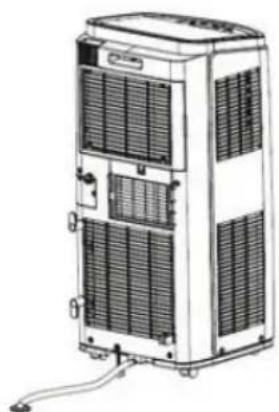
natural_image
Technical line drawing of a multi-tiered industrial air conditioning unit with cooling fins and ventilation slots (no text or labels)- Drain water from the middle drainage port.
Note: Water can be automatically emptied into a floor drain by attaching 13 mm inner diameter hose (not included)
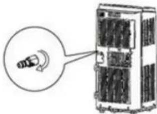
- Remove the drain cap by turning it anti clockwise then remove the rubber stopper from the spout.
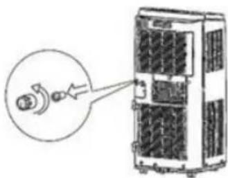
natural_image
Diagram of a device with an inset showing a connector or connector (no text or symbols present)- Screw the drain connector to the spout by turning clockwise.
natural_image
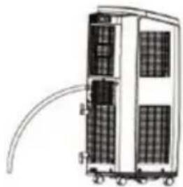
Illustration of a server rack with a magnified inset showing a cable or cable connection (no text or symbols present)- Insert the drainage hose into the drain connector.
natural_image
Diagram of a multi-tiered industrial or server unit with heat sinks and wiring (no text or symbols)Note: When using continuous drainage option from the middle drainage port, place portable on a level surface and make sure garden hose is clear of any obstructions and is directed downward. Placing portable on an uneven surface or improper hose installation may result in water filling up the chassis and causing the unit to shut off. Empty water in the chassis if shut off occurs, then check portable location and hose for proper setup.
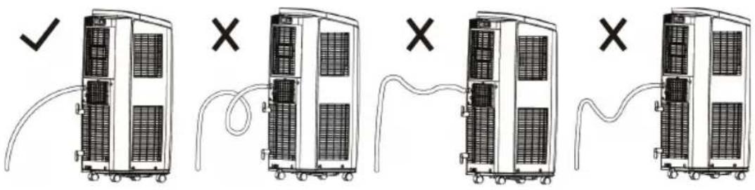
text_image
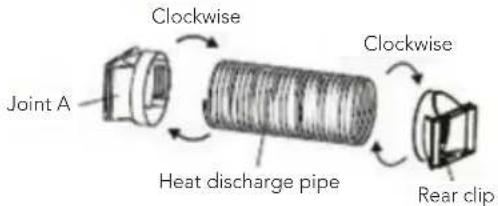
Diagram showing five stages of server rack installation with checkmark and X marks indicating status or failure.INSTALLATION OF HEAT DISCHARGE PIPE
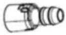
- Rotate joint A and Rear clip clockwise into the two ends of heat discharge pipe.
text_image
Joint A Clockwise Heat discharge pipe Clockwise Rear clip- Insert joint A of heat discharge pipe into the groove until you hear a sound.
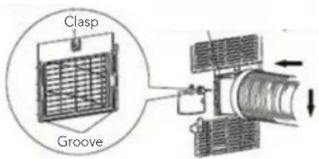
text_image
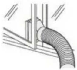
Clasp Groove- Lead the heat discharge pipe outdoors. For best effect, choose a window
without direct sunlight. Keep the other windows closed.
natural_image
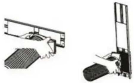
Diagram of a pipe with coiled duct and support structure (no text or symbols)- Slide and open the exhaust cover on the window panel and attach the Rear clip. (Optional). See the attached flyer for installing the window panel correctly.
natural_image
Two technical diagrams showing hands operating a mechanical component, one with a curved blade and the other with a rectangular block (no text or symbols)NOTE OF INSTALLING HEAT DISCHARGE PIPE
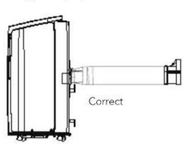
- In order to improve cooling efficiency, the heat discharge pipe should be as short as possible and flat without curve to ensure smooth heat discharge.
- The length of the heat discharge pipe is less than 1m. It is recommended to use it with shortest length.
- When installing, heat discharge pipe should be as flat as possible. Don't prolong the pipe or connect it with other heat discharge pipe.
text_image
Correct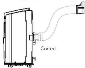
text_image
Correct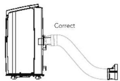
text_image
Correct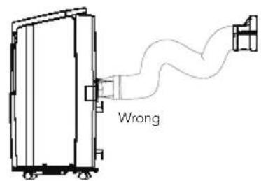
text_image
Wrong
text_image
BEYOND EXPECTATIONS 5 SINCE 1948 YEAR GUARANTEEGUARANTEE
Wilfa issues a 5 year guarantee on this product from the day of purchase is done. The guarantee covers production failure or defects that arise during the guarantee period. Your purchase receipt works as proof towards retailer if claiming your guarantee.
The guarantee is valid only for products that are bought and used in private households. The guarantee is not valid if the product is used commercially. The guarantee is not valid if the product is misused, used by negligence, if not following instructions given by Wilfa, if modified or if unauthorized reparation is done. The guarantee is also not valid for normal wear of the product, misuse, lack of maintenance, use of wrong electrical voltage or:
• Overloading of product
- Parts which are normally worn down
- Parts you can expect being replaced regularly (e.g. filter, battery etc.)
Instructions manual is also available at our website wilfa.com
PRODUCT SPECIFICATIONS
220V\~240V\~50Hz 1260W
Gas R290: 180gram
52/51/49 dB(A)
Dehumidifying 1.43 L/h
SUPPORT AND SPARE PARTS
For support please visit us at wilfa.com, and see our customer service/support page. Here you will find frequently asked questions, spare parts, tips and tricks and all our contact information.
RECYCLABILITY
This marking indicates that this product should not be disposed with other household wastes throughout the EU. To prevent possible harm to the environment or human health from uncontrolled waste disposal, recycle it responsibly to promote the sustainable reuse of material resources. To return your used device, please use the return and collection systems or contact the retailer where the product was purchased. They can take this product for environmentally safe recycling free of charge.
NO
NO
INNHOLD
36 VIKTIGE SIKKERHETSANVISNINGER
38 UNNTAKSKLAUSULER
39 KJ∅LEMIDDELET
41 DRIFTSMILJ∅
44 PRODUKTOVERSIKT - HOVEDENHET
46 PRODUKTOVERSIKT – BETJENINGSPANEL
48 PRODUKTOVERSIKT - FJERNKONTROLL
49 PRODUKTOVERSIKT - FJERNKONTROLLDISPLAY
51 BYTTE AV BATTERIER
52 RENGJ∅RING OG VEDLIKEHOLD
53 INSPEKSJONER
53 LANGVARIG OPPBEVARING
53 MERKNAD OM GJENBRUK
54 FEILS∅KING
56 FEILKODE
57 INSTALLASJON
64 GARANTI
65 PRODUKTSPESIFIKASJONER
65 SUPPORT OG RESERVEDELER
65 GJENVINNING
NO
VIKTIGE SIKKERHETSANVISNINGER
text_image
Technical diagram of an air conditioner unit with numbered components for identificationnatural_image
Technical line drawing of a dual-chamber industrial air conditioning unit with ventilation grilles and wheels (no text or symbols)NO
FJERNE VANNANSAMLING
natural_image
Line drawing of a multi-tiered industrial air conditioner unit with cooling fins and ventilation slots (no text or symbols)natural_image
Diagram of a device with an inset showing a connector or connector (no text or symbols present)natural_image
Illustration of a server rack with a magnified view showing a cable or cable connection (no text or symbols present)natural_image
Diagram of a multi-tiered industrial or storage unit with heat sinks and piping (no text or symbols)text_image
Diagram showing five stages of server rack connection with checkmark and X marks indicating status or failure.INSTALLASJON AV VARMEUTL∅PSR∅R
natural_image
Diagram of a pipe with ribbed duct and vertical support (no text or symbols)NO
natural_image
Two technical illustrations showing hands operating a device with a mesh component, no text or symbols present.MERKNAD OM INSTALLASJON AV VARMEUTL∅PSR∅R
text_image
Technical diagram of an air conditioner unit with numbered components for identificationnatural_image
Technical line drawing of a dual-chamber industrial air conditioning unit with cooling fans and wheels (no text or symbols)TA BORT UPPSAMLAT VATTEN
natural_image
Line drawing of a multi-tiered industrial air conditioner unit with cooling fins and ventilation slots (no text or symbols)natural_image
Diagram of a device with a magnified inset showing a connector or connector (no text or symbols present)natural_image
Illustration of a server rack with a magnified inset showing a cable or cable connection (no text or symbols present)natural_image
Diagram of a multi-tiered server or rack unit with visible internal components and wiring (no text or symbols)text_image
Diagram showing five stages of server rack installation with checkmark and X marks indicating status or failure.INSTALLATION AV VÄRMEUTLOPPSRÖR
natural_image
Diagram of a pipe connection with a vertical support and horizontal lines, no text or symbols presentnatural_image
Two technical illustrations of a mechanical assembly, showing hands operating a component with no visible text or symbols.SE
ATT TÄNKA PÅ NÄR MAN MONTERAR UTLOPPSRÖRET
text_image
Technical diagram of an air conditioner unit with numbered parts for identification– Unormal lyd under betjening.
- Dårlig lugt.
-Vandlækage.
natural_image
Technical line drawing of a dual-chamber industrial air conditioning unit with cooling fans and wheels (no text or symbols)FJERNELSE AF OPSAMLET VAND
natural_image
Line drawing of a multi-tiered industrial air conditioner unit with cooling fins and ventilation slots (no text or symbols)DK
natural_image
Diagram of a device with an inset showing a connector or connector (no text or symbols present)natural_image
Illustration of a device with a magnified view showing a small object inside (no text or symbols)natural_image
Diagram of a multi-tiered industrial or storage unit with heat sinks and connecting pipes (no text or labels)text_image
Diagram showing five stages of server rack connection with checkmark and X marks indicating status or failure.INSTALLATION AF VARMEUDLEDNINGSR∅R
natural_image
Diagram of a pipe connection with a cylindrical component (no text or symbols)natural_image
Two technical illustrations of a mechanical assembly, showing hands operating a component with no visible text or symbols.DK
BEMÆRKNING TIL INSTALLATION AF VARMEUDLEDNINGSR∅R
text_image
Technical diagram of an air conditioner unit with numbered parts for identification⑥ Sleep-valmiustilapainike
⑧ Health-terveyspainike
natural_image
Technical line drawing of a dual-chamber industrial air conditioning unit with cooling fans and wheels (no text or symbols)KERÄTYN VEDEN POISTAMINEN
natural_image
Line drawing of a multi-tiered industrial air conditioner unit with cooling fins and ventilation slots (no text or symbols)Fl
natural_image
Diagram of a device with an inset showing a connector or connector (no text or symbols present)natural_image
Illustration of a device with a magnified inset showing a connector or cable (no text or symbols present)natural_image
Diagram of a multi-tiered industrial or server unit with heat sinks and wiring (no text or symbols)text_image
Diagram showing five stages of server rack installation with checkmark and X marks indicating failure or invalid conditions.LÄMMÖNPOISTOPUTKEN ASENTAMINEN
natural_image
Diagram of a pipe connection with visible ductwork and support structure (no text or symbols)natural_image
Two technical diagrams showing mechanical assembly or assembly process, with no visible text or symbols.Fl
HUOMAUTUS LÄMMÖNPOISTOPUTKEN ASENTAMISESTA
text_image
Technical diagram of an air conditioner unit with numbered components for identificationnatural_image
Technical line drawing of a dual-chamber industrial air conditioning unit with ventilation grilles and wheels (no text or symbols)ANGESAMMELTES WASSER ENTFERNEN
natural_image
Illustration of a multi-tiered industrial air conditioner unit with cooling fins and ventilation slots (no text or symbols visible)natural_image
Diagram of a device with an inset showing a connector or connector (no text or symbols present)natural_image
Diagram of a device with a magnified inset showing a small component (no text or symbols present)natural_image
Diagram of a multi-tiered industrial or server unit with solar panels and connecting tubing (no text or symbols)text_image
Diagram showing five stages of server rack connection with checkmark and X marks indicating status or failure.MONTAGE DES WÄRMEAUSLASSROHRS
natural_image
Diagram of a pipe connection with a vertical support and horizontal lines, no text or symbols presentnatural_image
Two technical illustrations showing hands operating a device with a mesh component and a close-up view of the next component (no text or symbols present)HINWEIS ZUR MONTAGE DER WÄRMEAUSLASSROHRS
214 PROBLEEMOPLOSSING
216 FOUTCODE
217 INSTALLATIE
224 GARANTIE
225 PRODUCTSPECIFICATIES
225 SUPPORT EN RESERVEONDERDELEN
225 RECYCLING
BELANGRIJKE VEILIGHEIDSINSTRUCTIES
text_image
Technical diagram of an air conditioner unit with numbered parts for identificationNL
- Trek filter 2 eruit.
- Filter reinigen
natural_image
Technical line drawing of a dual-chamber industrial air conditioning unit with ventilation grilles and wheels (no text or symbols)NL
natural_image
Illustration of a multi-tiered industrial air conditioner unit with cooling fins and ventilation slots (no text or symbols visible)natural_image
Diagram of a device with an inset showing a connector or connector (no text or symbols present)natural_image
Illustration of a device with a magnified inset showing a cable or cable connection (no text or symbols present)natural_image
Diagram of a multi-tiered industrial or server unit with heat sinks and wiring (no text or symbols)text_image
Diagram showing five stages of server rack connection with checkmark and X marks indicating failure or invalid conditions.INSTALLATIE VAN DE WARMTEAFVOERLEIDING
natural_image
Diagram of a pipe connection with a wooden support structure (no text or symbols)natural_image
Two technical illustrations of a mechanical assembly or mounting bracket, showing hand positioning and clamping mechanism (no text or symbols)OPMERKING OVER HET INSTALLEREN VAN DE WARMTEAFVOERLEIDING
text_image
Technical diagram of an air conditioner unit with numbered parts for identificationPL
④ Przycisk Fan (Wentylator)
⑤ Przycisk Fan (Wentylator)
natural_image
Technical line drawing of a dual-chamber industrial air conditioning unit with ventilation grilles and wheels (no text or symbols)PL
USUWANIE ZEBRANEJ WODY
natural_image
Line drawing of a multi-tiered industrial air conditioner unit with cooling fins and ventilation slots (no text or symbols)natural_image
Diagram of a device with an inset showing a connector or connector (no text or symbols present)natural_image
Illustration of a device with a magnified inset showing a connector or cable (no text or symbols present)PL
natural_image
Diagram of a multi-tiered industrial or server unit with heat sinks and wiring (no text or symbols)text_image
Diagram showing five stages of server rack connection with checkmark and X marks indicating status or failure.MONTAŻ RURY ODPROWADZAJĄCEJ CIEPŁO
natural_image
Diagram of a pipe connection with a coiled duct (no text or symbols)natural_image
Two technical illustrations showing hands operating a device with a cable and a battery (no text or symbols present)UWAGA DOTYCZĄCA MONTAŻU RURY ODPROWADZAJĄCEJ CIEPŁO
262 CLAUSES D'EXCEPTION
264 LE RÉFRIGÉRANT
266 ENVIRONNEMENT D'UTILISATION
268 APERÇU DES PRODUITS : APPAREIL PRINCIPAL
270 PRÉSENTATION DU PRODUIT : PANNEAU DE COMMANDE
272 PRÉSENTATION DU PRODUIT : TÉLÉCOMMANDE
273 PRÉSENTATION DU PRODUIT : AFFICHAGE DE LA TÉLÉCOMMANDE
275 REMPLACEMENT DES PILES
276 NETTOYAGE ET ENTRETIEN
277 CONTRÔLES
text_image
Technical diagram of an air conditioner unit with numbered parts for identificationFR
natural_image
Technical line drawing of a dual-chamber industrial air conditioning unit with cooling fans and wheels (no text or symbols)FR
RETRAIT DE L'EAU RECUEILLIE
natural_image
Line drawing of a multi-tiered industrial air conditioner unit with cooling fins and ventilation slots (no text or symbols)- Vidanger l'eau de l'orifice de vidange central.
natural_image
Diagram of a device with an inset showing a connector or connector (no text or symbols present)natural_image
Diagram of a device with a magnified inset showing a connector or cable connection (no text or symbols present)natural_image
Diagram of a multi-tiered industrial or server unit with heat sinks and wiring (no text or labels)text_image
Diagram showing five stages of server rack installation with checkmark and X marks indicating status or failure.INSTALLATION DU TUYAU D'ÉVACUATION DE LA CHALEUR
text_image
Fermoir RainureFR
natural_image
Diagram of a pipe connection with a vertical support and horizontal lines, no text or symbols presentnatural_image
Two technical illustrations of a mechanical assembly, showing hands operating a component (no text or symbols present)REMARQUE POUR L'INSTALLATION DU TUYAU D'ÉVACUATION DE LA CHALEUR
text_image
Incorrect
text_image
BEYOND EXPECTATIONS 5 SINCE 1948 YEAR GUARANTEEGARANTIE
CARACTÉRISTIQUES DU PRODUIT
220V\~240V\~50Hz 1260W
Gaz R290: 180gram
52/51/49 dB(A)
Déshumidification 1.43 L/h
ASSISTANCE ET PIÈCES DÉTACHÉES
text_image
Technical diagram of an air conditioner unit with numbered components for identificationIT
⑧ Pulsante "Health" (Salute)
natural_image
Technical line drawing of a dual-chamber industrial air conditioning unit with cooling fans and wheels (no text or symbols)IT