
Chill Connected AC1B-7000C - Air Conditioning WILFA - Free user manual and instructions
Find the device manual for free Chill Connected AC1B-7000C WILFA in PDF.

| Product Type | Monoblock portable air conditioner |
| Brand | Wilfa |
| Model | Chill Connected AC1B-7000C |
| Cooling power | 7000 BTU/h (estimated from reference) |
| Refrigerant | R290 (propane), flammable |
| Operating modes | Cooling, dehumidification (drying), ventilation, sleep |
| Set temperature range | 16 °C to 32 °C |
| Fan speed | High and low |
| Timer | 1 h to 24 h (programmed on/off) |
| Child safety | Yes (panel lock) |
| Remote control | Yes, included |
| Connectivity | Wi-Fi and Bluetooth via WiLife app (iOS 11.0+ / Android 5.0+) |
| Air filter | Washable, cleaning recommended every 2 weeks |
| Drainage | Automatic in cooling mode (evaporation), manual with hose in drying mode |
| Power supply | 220-240 V, 50 Hz (European standard) |
| Minimum room area | Greater than 8 m² |
| Included accessories | Exhaust hose, hose connector, window kit adapter, window brackets, remote control |
| Warranty | 5 years |
Frequently Asked Questions - Chill Connected AC1B-7000C WILFA
User questions about Chill Connected AC1B-7000C WILFA
0 question about this device. Answer the ones you know or ask your own.
Ask a new question about this device
Download the instructions for your Air Conditioning in PDF format for free! Find your manual Chill Connected AC1B-7000C - WILFA and take your electronic device back in hand. On this page are published all the documents necessary for the use of your device. Chill Connected AC1B-7000C by WILFA.
USER MANUAL Chill Connected AC1B-7000C WILFA
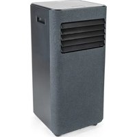
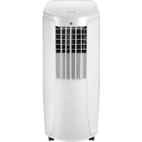
natural_image
Exterior view of a gray industrial air conditioner unit with ventilation slots and a handle (no text or symbols visible)CHILL CONNECTED
AIR CONDITION AC1W-7000/AC1B-7000C/AC1B-9000C
EN · Instruction manual
NO · Bruksanvisning
SE . Bruksanvisning
4 IMPORTANT SAFETY INSTRUCTIONS
6 SYMBOLS FROM THE UNIT AND USER MANUAL
7 OPERATIONAL PRECAUTIONS
10 PRODUCT OVERVIEW
11 INSTALLATION
11 ATTACH THE EXHAUST HOSE
13 CONTROL PANEL AND DISPLAY
14 REMOTE CONTROL
14 SETTINGS
16 TIMER SETTING (1HOUR-24HOURS)
16 DRAINAGE
17 DISASSEMBLY AND CLEANING
18 TROUBLESHOOTING
19 STORAGE
19 WIFI DESCRIPTION
21 TROUBLESHOOTING CONNECTION
22 GUARANTEE
23 PRODUCT SPECIFICATIONS
23 SUPPORT AND SPARE PARTS
23 RECYCLABILITY
IMPORTANT SAFETY INSTRUCTIONS
- Read this instruction manual thoroughly before use and save it for future reference. It is also available at our website; wilfa.com.
- This appliance can be used by children aged from 8 years and above and persons with reduced physical, sensory or mental capabilities or lack of experience and knowledge if they have been given supervision or instruction concerning use of the appliance in a safe way and understand the hazards involved. Children shall not play with the appliance. Cleaning and user maintenance shall not be done by children without supervision.
- This product is intended for indoor, non-industrial, non-commercial; household use only.
- If the supply cord is damaged, it must be replaced by the manufacturer, its service agent or similarly qualified persons in order to avoid a hazard.
- The unit is designed only for use with R-290(propane) gas as the designated refrigerant.
- The refrigerant loop is sealed. Only a qualified technician should attempt to service!
-
Do not discharge the refrigerant into the atmosphere.
-
R-290 (propane) is flammable and heavier than air. It accumulates first in low areas but can be circulated by fans.
- If propane gas is present or even suspected, do not allow untrained personnel to attempt to find the cause.
- The propane gas used in the unit has no odor.
- The lack of smell does not indicate a lack of escaped gas.
- If a leak is detected, immediately evacuate all persons from the room, ventilate the room and contact the local fire department to advise them that a propane leak has occurred.
- Do not let any persons back into the room until the qualified service technician has arrived and that technician advises that it is safe to return to the room.
- No open flames, cigarettes or other possible sources of ignition should be used inside or in the vicinity of the units.
- Component parts are designed for propane and non-incentive and non-sparking. Component parts shall only be replaced with identical repair parts.
FAILURE TO ABIDE BY THIS WARNING COULD RESULT IN AN EXPLOSION, DEATH, INJURY AND PROPERTY DAMAGE.
The environmentally friendly R290 is used as the refrigerant. R290 has no damaging influence on the ozone layer (ODP), a negligible greenhouse effect (GWP) and is available worldwide. Because of its efficient energy properties, R290 is highly suitable as a coolant for this application. Special precautions must be taken into consideration due to the coolant's high flammability.
SYMBOLS FROM THE UNIT AND USER MANUAL
Warning
This unit uses a flammable refrigerant.
If refrigerant leaks and comes in contact with fire or heating part, it will create harmful gas and there is a risk of fire.

Read the USER MANUAL carefully before operation.

Further information is available in the USER MANUAL, SERVICE MANUAL, and the like.

Service personnel are required to carefully read the USER MANUAL and SERVICE MANUAL before operation.
OPERATIONAL PRECAUTIONS
WARNING- to reduce the risk of fire, electric shock or injury to persons or property:
- Always operate the unit from a power source of equal voltage, frequency and rating as indicated on the product identification plate.
• Always use a power outlet that is grounded. - Unplug the power cord when cleaning or when not in use.
- Do not operate with wet hands. Prevent water from spilling onto the unit.
- Do not immerse or expose the unit to rain, moisture or any other liquid.
- Do not leave the unit running unattended. Do not tilt or turn over the unit.
- Do not unplug while the unit is operating.
- Do not unplug by pulling on the power cord.
- Do not use an extension cord or an adapter plug.
- Do not put objects on the unit.
- Do not climb or sit on the unit.
-
Do not insert fingers or other objects into the air outlet.
-
Do not touch the air inlet or the aluminum fins of the unit.
- Do not operate the unit if it is dropped, damaged or showing signs of product malfunction.
- Do not clean the appliance with any chemicals.
- Ensure the unit is far away from fire, inflammable, or explosive objects.
- The unit shall be installed in accordance with national wiring regulations.
- Do not use means to accelerate the defrosting processorto clean, other than those recommended by the manufacture.
- The appliance shall be stored in a room without continuously operation sources (for example: open flames, an operating gas appliance or an operating electric heater).
- The appliance shall be stored so as to prevent mechanical damage from occurring.
- Do not piece or burn, even after use.
- Be aware that refrigerants may not contain an odour.
-
Pipe-work shall be protected from physical damage and shall not be installed in an unventilated space, if that space is smaller than 8m^2 .
-
Compliance with national gas regulations shall be observed.
- Keep any required ventilation openings clear of obstruction.
- The appliance shall be stored in a well-ventilated area where the room size corresponds to the room area as specified for operation.

WARNING
Any person who is involved with working on or breaking into a refrigerant circuit should hold a current valid certificate from an industry-accredited assessment authority, which authorizes their competence to handle refrigerants safely in accordance with an industry, recognized assessment specification.

WARNING
Servicing shall only be performed as recommended by the equipment manufacturer. Maintenance and repair requiring the assistance of other skilled personnel shall be carried out under the supervision of the person competent in the use of flammable refrigerants.
PRODUCT OVERVIEW
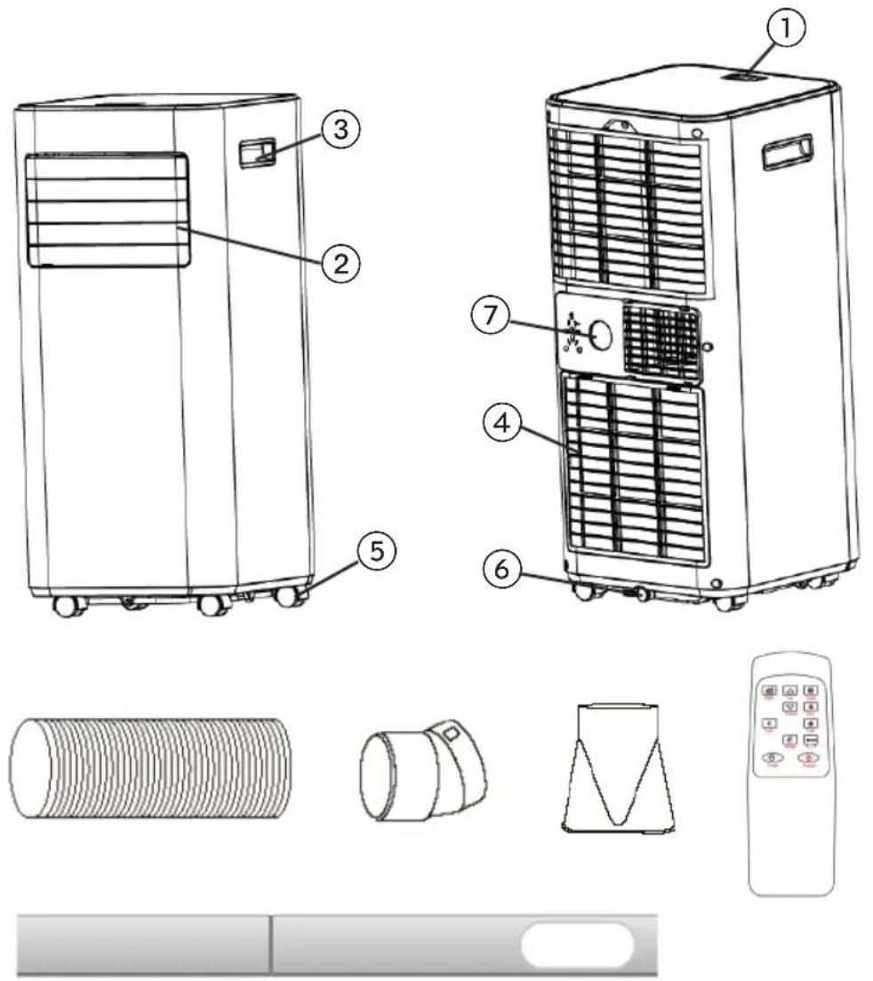
- Control panel
- Air outlet with adjustable louver
- Handle
- Air inlet with air filter
- Wheel
- Drainage hole
- Air exhaust
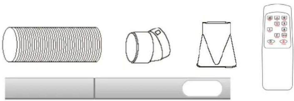
Accessories:
- Exhaust hose
- Hose connector
- Window kit adapter
- Remote control
- Window bracket
Note: The appearance is only for reference. Please see the real product for detailed information.
INSTALLATION
- If tipped more than 45^ , allow the unit to set upright for at least 24 hours before start up.
- Place the unit on a firm, level surface in an area with at least 50cm of free space around it to allow for proper air circulation.
- Do not operate in close proximity to walls, curtains, or other objects that may block air inlet and outlet. Keep the air inlet and outlet free of obstacles.
-
Never install the unit where it could be subject to:
-
Heat sources such as radiators, heat registers, stoves or other products that produce heat.
- Direct sunlight
- Mechanical vibration or shock
- Excessive dust
– Lack of ventilation, such as a cabinet or bookcase - Uneven surface
WARNING!

• Install the unit in rooms which exceed 8 m^2 .
- Do not install the unit in a place where inflammable gas may leak.
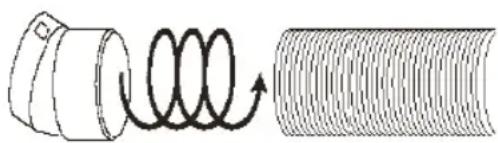
ATTACH THE EXHAUST HOSE
The air conditioner requires being vented outside so that the exhaust air can escape the room which coming from the appliance contains waste heat and moisture.
Do not replace or extend exhaust hose which will result in decreased efficiency, even worse shut down the unit due to low backpressure.
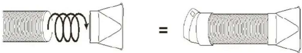
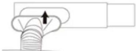
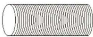
Step 1: Connect the hose connector to one end of the exhaust hose.
natural_image
Diagram showing a coiled spring and its helical end, no text or symbols presentEN
Step 2: Connect the windows kit adapter to the other end of the exhaust hose.
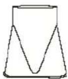
Step 3: Adjust the window brackets to the width or height of your window, and insert the plastic pins to fix the desired position.
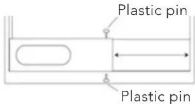
Note: do not install the window bracket to the window. This step is only to adjust to the size of your window. The bracket should be removed after the size is adjusted.
Step 4: Connect the window bracket to the window kit adapter. Ensure all connections are tight and installed properly.
natural_image
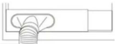
Pure diagram of a mechanical component with an arrow indicating direction (no text or symbols)Step 5: Connect the window bracket to the window.
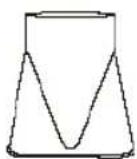
natural_image
Pure technical line drawing of a mechanical component with no text or symbolsStep 6: Adjusting the length of the flexible exhaust hose and avoid bends in the hose. Then place AC near an electrical outlet.
CONTROL PANEL AND DISPLAY
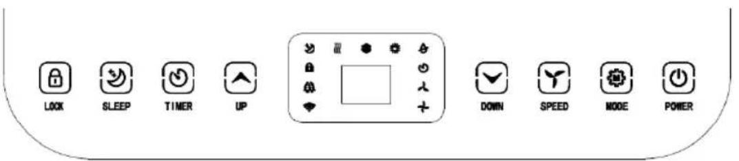
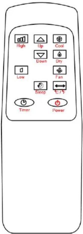
1 LOCK Press and hold this key to turn on or turn off the child lock function
2 MODE Mode button Press to switch the operation mode between fan, cooling and dehumidifier.
3 UP Increasing the desired temperature (16°C - 32°C) or timer setting
4 POWER Press to switch the machine on or off
5 DOWN Decreasing the desired temperature or timer setting.
6 SPEED Press to switch the fan speed between HIGH and LOW
7 TIMER Sets a time for the unit to automatically start or stop.
8 SLEEP Press to enter sleep mode. Can only be entered in cooling mode
9 Fan speed The display for fan speed in High or low
10 Led Display This LED Display the Room Temperature or Time Setting
11 Mode Display This display the Mode Setting between fan, cooling and dehumidifier
EN
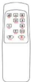
REMOTE CONTROL
SETTINGS
START-UP AND SHUTDOWN
- Press POWER to turn the unit on.
- Press MODE button to select the desired operation mode.
- Press POWER again to turn off the power.
OPERATION MODE
The unit has four operation modes: Cool, dry, fan, sleep.
COOLING YOUR ROOM
- Select the cool mode to lower the temperature in your room.
- Press MODE button repeatedly until the COOL indicator lights up.
-
Press Up/Down button to adjust the temperature which is displayed on the screen. The temperature can be set between 16°C and 32°C.
-
Press SPEED button repeatedly until the desired fan speed indicator lights up.
- To control the direction of the air flow horizontally, please adjust the inner louver by hand.
Note: The air conditioner stops if the room temperature is lower than selected temperature.
VENTILATING YOUR ROOM
- Press MODE button repeatedly until the FAN indicator lights up.
- In ventilation mode the room air is circulated, but not cooled.
- Press SPEED button repeatedly to select the fan speed as desired.
DRYING YOUR ROOM
- Press MODE button on the control panel or remote control, the dry indicator lights up. The fan speed is unable to select. User should connect the hose to the drain outlet at the bottom of the unit.
Note: In this mode, the fan speed switches over to low speed and cannot be selected.
SLEEP MODE
- The sleep button can only be set in cooling mode.
- The machine enters sleep mode, all lights are dimmed at the same time, and the buzzer is disabled in sleep mode:
- 1 hour after sleep mode is turned ON, the set temperature will automatically increase by 1^ , and after another hour, the set temperature will automatically increase by 1^ .
- After sleep mode has been ON for 2 hours, the set temperature will no longer increase.
- Fan output during sleep mode: the fan automatically turns to low setting. The wind speed output is low wind and cannot be adjusted. After exiting sleep mode, the wind speed can again be set by the user.
TIMER SETTING (1HOUR-24HOURS)
The timer has two ways of operation:
| To turn off(When power on) | → | Press the Timer key to turn on the timer function. | → | Press Up /Down repeatedly to set the delay OFF time. |
| To turn on(When power off) | → | Press the Timer key to turn on the timer function. | → | Press Up /Down repeatedly to set the delay ON time. |
| Cancel timer | → | Press Up /Down repeatedly until the LED shows '00'.Note: by pressing POWER you will also cancel the timer | ||
OVERLOAD PROTECTION
In the event of a power loss, to protect the compressor there is a 3-minute delay until the compressor restarting.
DRAINAGE
SELF-EVAPORATING SYSTEM
The self-evaporating system uses the collected water to cool the condenser coils for better, more efficient performance. There is no need to empty the drainage tank in cooling mode, except in high humidity conditions. In drying mode, the drainage tank needs to be emptied. The condensed water evaporates at the condenser and disappears through the exhaust hose.
For continuous operation or unattended operating in drying mode, please connect the attached drain hose to the unit. Condensed water can automatically run into a bucket or drain.
- Switch off the unit before operating.
- Remove the plug of the water outlet opening and keep it in safe area.
- Securely and properly connect the drain hose. Make sure it is not kinked and clear of obstruction.
- Place the outlet of hose over a drain or bucket and ensure that water can freely flow out of the unit.
- Do not submerge the end of hose into water; otherwise it can cause "Air Lock" in the hose.

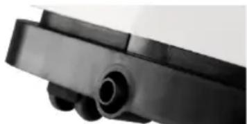
Remove the rubber sealing plug

natural_image
Close-up of a black mechanical component with a cylindrical opening, labeled 'Continuous drain hose' (no other text or symbols visible)TO AVOID WATER SPILLAGE
- As the negative pressure of condensate drain pan is large, tilt the drain hose downward toward the floor. It is appropriate that the degree of inclination should exceed 20 degrees.
- Straighten the hose to avoid a trapping water in the hose.
DISASSEMBLY AND CLEANING
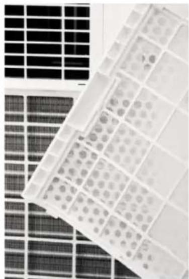
CLEANING THE AIR FILTER (EVERY TWO WEEKS)
Dust collects on the filter and restricts the airflow. The restricted airflow reduces the efficiency of the system and if it becomes blocked it can cause damage to the unit.
The air filter requires regular cleaning. The air filter is removable for easy cleaning. Do not operate the unit without an air filter, or the evaporator may be contaminated.
- Press POWER button to switch off the unit and unplug the power cord.
- Remove the filter mesh from the unit.
- Use a vacuum cleaner to vacuum dust from the filter.
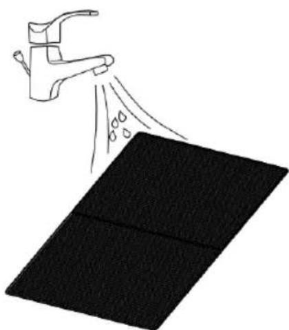
- Turn the filter over and rinse the air filter under running water. Let the water run through the filter in the opposite direction of air flow. Set aside and allow the filter to air dry completely before reinstalling.
natural_image
Close-up of a grid of small circular patterns on a solar panel array (no text or symbols visible)Switch off the unit and remove the two air filters.
natural_image
Illustration of a faucet spraying water onto a black rectangular surface (no text or symbols)Rinse the air filter under running water.
TROUBLESHOOTING
| Problem Possible reasons Solutions | ||
| The unit is not operating | Check the power connection in securely. | Insert the power cord securely into the wall outlet. |
| Check if the water level indicator lights up? | Empty the drain pan by removing the rubber plug. | |
| Check the room temperature. | The range of operating temperature is 5-35°C. | |
| The unit works with reduced capacity. | Check the air filter for dust. | Clean the air filter as necessary. |
| Check if the air duct is blocked. | Clear the obstacle. | |
| Check if the door or window is open. | Keep the door and windows closed. | |
| Check if the desired operating mode is selected and the temperature is properly set. | Set the mode and temperature at desired point according the manual (see page 16). | |
| The exhaust hose is detached. | Make sure the exhaust hose is securely attached. | |
| Water Leakage Overflow while moving the unit. | Empty the water tank before transport. | |
| Straighten the hose to avoid a trapping water. | ||
| Excessive Noise Check if the unit is securely positioned. | Place the unit on horizontal and firm floor. | |
| Secure and tighten the parts. | ||
| Noise comes from flowing refrigerant. This is normal. | ||
STORAGE
Long-Term Storage - If you will not be using the unit for an extended period of time (more than a few weeks) it is best to clean the unit and dry it out completely. Please store the unit per the following steps:
- Unplug the unit and remove exhaust hose and window kit store with the unit.
- Drain the remaining water from the unit.
- Clean the filter and let the filter dry completely in a shaded area.
- Re-install the filter at its position.
- The unit must be kept in upright position when in storage.
- Preserving the machine in ventilating, dry, non-corrosive gas and safe place indoor.
WIFI DESCRIPTION
INFORMATION ON THE APP "WILIFE"
The "WiLife" app is available for android and iOS. Scan the corresponding QR code to get directly to the download.

INFORMATION ON HOW TO USE THE APP
This appliance allows you to operate the appliance via your home net-work. A prerequisite is a permanent Wi-Fi connection to your router and the free app "WiLife".
We recommend disconnecting the appliance from the power supply when you are away from home to prevent unintentional switching on while you are on the road.
SYSTEM REQUIREMENT FOR USE OF THE APP
- iOS 11.0 or higher
- Android 5.0 or higher
- Bluetooth 4.2
EN
COMMISSIONING VIA THE APP FOR WIFI
- Install the "WiLife" app. Create a user account.
- Activate the Wi-Fi function in the settings of your appliance.
- Place the appliance at a distance of about 5 meters to your router.
- Press and hold the Timer button for about 3 seconds. The Wi-Fi lamp will flash rapidly.
- Launch the app and select "+".
- Select the "Air Conditioner" menu and follow the instructions on the display.
- Once the appliance has been successfully connected, the Wi-Fi lamp lights up. Now you can operate the appliance using the app.
- Press and hold the Timer button for about 3 seconds, the appliance disconnect, the Wi-Fi lamp lights off.
COMMISSIONING VIA THE APP FOR BLUETOOTH
- Install the "WiLife" app. Create a user account.
- Turn on the Bluetooth on your smartphone.
- Turn on the device.
- Within 10 meters of the device, open the app, and the device should appear automatically on the bottom of your screen
- Follow further instructions on the app
TROUBLESHOOTING CONNECTION
Problem Solutions
| The device does not show up in the app when you try to connect with wi-fi | Make sure your Bluetooth is turned on on your smartphone. Turn your internet off for 3 minutes. Keep your phone within 10 meters of the unit and try to connect again using bluetooth. |
| The device does not show up in the app when you try to connect with Bluetooth | Press the + in the upright corner and press “large home appliances”, then add air conditioner. Press and hold the timer button 3 seconds until the wi-fi lamp flashed rapidly. Then follow the instructions on the app |
| The app is not working to control the device | Make sure you are connected to the wi-fi. If the wi-fi is down, make sure you are connected to BluetoothTurn the device off for 5 seconds and turn it back on.Restart the application. |

GUARANTEE
Wilfa issues a 5 year guarantee on this product from the day of purchase is done. The guarantee covers production failure or defects that arise during the guarantee period. Your purchase receipt works as proof towards retailer if claiming your guarantee.
The guarantee is valid only for products that are bought and used in private households. The guarantee is not valid if the product is used commercially. The guarantee is not valid if the product is misused, used by negligence, if not following instructions given by Wilfa, if modified or if unauthorized reparation is done. The guarantee is also not valid for normal wear of the product, misuse, lack of maintenance, use of wrong electrical voltage or:
• Overloading of product
- Parts which are normally worn down
- Parts you can expect being replaced regularly (e.g. filter, battery etc.)
Instructions manual is also available at our website wilfa.com
PRODUCT SPECIFICATIONS
AC1W-7000/AC1B-7000C: 220-240V\~, 50Hz, 780W, 130g R290
AC1B-9000C: 220-240V\~, 50Hz, 1005W, 170g R290
SUPPORT AND SPARE PARTS
For support please visit us at wilfa.com, and see our customer service/support page. Here you will find frequently asked questions, spare parts, tips and tricks and all our contact information.
RECYCLABILITY
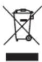
This marking indicates that this product should not be disposed with other household wastes throughout the EU. To prevent possible harm to the environment or human health from uncontrolled waste disposal, recycle it responsibly to promote the sustainable reuse of material resources. To return your used device, please use the return and collection systems or contact the retailer where the product was purchased. They can take this product for environmentally safe recycling free of charge.

Releasing refrigerant into atmosphere is strictly forbidden!
NO
NO
INNHOLD
26 VIKTIGE SIKKERHETSINSTRUKSJONER
28 SYMBOLER FRA ENHETEN OG BRUKSANVISNINGEN
29 FORHOLDSREGLER VED BRUK
32 PRODUKTOVERSIKT
33 INSTALLASJON
33 FESTE AVTREKKSSLANGE
35 BETJENINGSPANEL OG DISPLAY
36 FJERNKONTROLL
36 INNSTILLINGER
38 TIDSINNSTILLING (1–24 TIMER)
38 AVL∅P
39 DEMONTERING OG RENGJ∅RING
40 FEILS∅KING
41 OPPBEVARING
41 WI-FI-BESKRIVELSE
44 GARANTI
45 PRODUKTSPESIFIKASJONER
45 SUPPORT OG RESERVEDELER
45 GJENVINNING
VIKTIGE SIKKERHETSINSTRUKSJONER

natural_image
Pure 3D illustration of a cylindrical object with evenly spaced horizontal lines, no text or symbols present.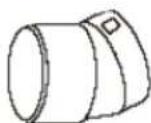

natural_image
Simple gray rectangular button with a white oval on the right side (no text or symbols)natural_image
Diagram showing a coiled spring and its corresponding helical structure (no text or symbols)natural_image
Simple line drawing of a plant stem with an arrow indicating upward motion (no text or symbols)natural_image
Pure technical line drawing of a pipe fitting with no text or symbolsTIDSINNSTILLING (1–24 TIMER)
natural_image
Close-up of a mechanical component with a labeled part 'Fjern' (no other visible text or symbols)Fjern gummipluggen

natural_image
Close-up of a grid of small circular patterns on a solar panel array (no text or symbols visible)natural_image
Illustration of a faucet spraying water onto a black rectangular surface (no text or symbols)Skyll luftfilteret under rennende vann.
FEILS∅KING
natural_image
Diagram of a coiled spring and its helical end, showing deformation (no text or symbols)natural_image
Pure diagram of a mechanical component with an arrow indicating direction (no text or symbols)natural_image
Pure technical line drawing of a pipe fitting with no text or symbolsnatural_image
Close-up of a mechanical component labeled 'Ta bort' (no other visible text or symbols)natural_image
Close-up of a grid-patterned panel with solar panels in the background (no text or symbols visible)natural_image
Illustration of a faucet spraying water onto a black rectangular surface (no text or symbols)INFORMATION OM APPEN "WILIFE"
natural_image
Diagram of a coiled spring and its helical end, showing deformation (no text or symbols)natural_image
Diagram showing a coiled spring connected to a conical component, with no text or symbols present.natural_image
Simple line drawing of a plant or leaf structure with an arrow indicating upward motion (no text or symbols)natural_image
Pure technical line drawing of a pipe fitting with no text or symbolsnatural_image
Close-up of a mechanical component with a labeled part 'Fjern' (no other visible text or symbols)Fjern gummiforseglingsproppen
natural_image
Close-up of a black mechanical component with a cylindrical opening (no visible text or symbols)natural_image
Close-up of a grid of small circular patterns on a solar panel array (no text or symbols visible)natural_image
Illustration of a faucet spraying water onto a black rectangular surface (no text or symbols)Skyl luftfilteret under rindende vand.
FEJLFINDING
INFORMATION OM APP'EN "WILIFE"
Appen "WiLife" findes til android og iOS. Scan QR-koden for at komme direkte til download.

INFORMATION OM, HVORDAN DU BRUGER APPEN
natural_image
Diagram of a coiled spring and its helical end, showing deformation (no text or symbols)natural_image
Diagram showing a coiled spring connected to a conical component, with no text or symbols present.natural_image
Simple line drawing of a plant with a curved stem and upward arrow, no text or symbols presentnatural_image
Pure technical line drawing of a pipe fitting with no text or symbolsnatural_image
Close-up of a mechanical component with labeled parts 'Irrota' (no other visible text or symbols)Irrota kumitulppa

natural_image
Close-up of a grid of small circular patterns on a solar panel array (no text or symbols visible)natural_image
Simple line drawing of a faucet spraying water onto a black rectangular surface (no text or symbols)DE
natural_image
Pure 3D illustration of a cylindrical object with evenly spaced horizontal lines, no text or symbols present.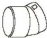

natural_image
Simple gray rectangular button with a white oval on the right side (no text or symbols)natural_image
Diagram of a coiled spring and its helical end, showing internal structure without any text or symbolsnatural_image
Pure diagram of a mechanical component with an arrow indicating direction (no text or symbols)natural_image
Pure technical line drawing of a mechanical component without any text, numbers, or symbolsnatural_image
Close-up of a grid of small circular patterns on a solar panel array (no text or symbols visible)natural_image
Illustration of a faucet spraying water onto a black surface (no text or symbols)
natural_image
Illustration of four household appliances: a cylindrical tube, a cylindrical device with a handle, a triangular container, and a remote control (no text or symbols)natural_image
Diagram showing a coiled spring and a coiled cable with directional arrows (no text or symbols)natural_image
Simple line drawing of a leafy plant with an arrow pointing upward, next to a rectangular block (no text or symbols)natural_image
Pure technical line drawing of a pipe fitting with no text or symbolsnatural_image
Close-up of a grid-patterned surface with circular indentations, no visible text or symbolsnatural_image
Simple line drawing of a faucet spraying water onto a black surface (no text or symbols)INFORMATIE OVER DE APP 'SMART LIFE-SMART LIVING'
PROBLEEMOPLOSSING VERBINDING
natural_image
Illustration of four household appliances: a cylindrical tube, a cylindrical device with a handle, a triangular container, and a remote control (no text or symbols)PL
natural_image
Diagram showing a coiled spring attached to a cylindrical component, with no text or symbols present.PL
natural_image
Diagram showing a coiled spring being combined into a conical component (no text or symbols present)natural_image
Pure diagram of a mechanical component with an arrow indicating direction (no text or symbols)natural_image
Pure technical line drawing of a pipe fitting or duct (no text or symbols)natural_image
Close-up of a mechanical component with a black cylindrical part and a small circular feature, labeled 'Wyjmij gumowy' below (no other text or symbols visible)natural_image
Close-up of a grid of small circular patterns on a solar panel array (no text or symbols visible)natural_image
Illustration of a faucet spraying water onto a black rectangular surface (no text or symbols)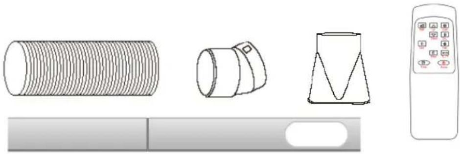
natural_image
Illustration of various household appliances including a cylindrical tube, a cylindrical device with a handle, a triangular container, and a remote control (no text or symbols)natural_image
Diagram showing a coiled spring and its helical texture (no text or symbols)natural_image
Pure diagram of a mechanical component with an arrow indicating direction, no text or symbols presentnatural_image
Pure technical line drawing of a mechanical component without any text, numbers, or symbolsnatural_image
Close-up of a black mechanical component with a cylindrical opening (no visible text or symbols)Tuyau de vidange continu
natural_image
Close-up of a grid-patterned plastic tray with circular indentations, placed on a dark surface (no text or symbols visible)natural_image
Illustration of a faucet spraying water onto a black rectangular surface (no text or symbols)CARACTÉRISTIQUES DU PRODUIT
AC1W-7000/AC1B-7000C: 220-240V\~, 50Hz, 780W, 130g R290
AC1B-9000C: 220-240V\~, 50Hz, 1005W, 170g R290
ASSISTANCE ET PIÈCES DÉTACHÉES

- CHILL CONNECTED
- IMPORTANT SAFETY INSTRUCTIONS
- FAILURE TO ABIDE BY THIS WARNING COULD RESULT IN AN EXPLOSION, DEATH, INJURY AND PROPERTY DAMAGE.
- SYMBOLS FROM THE UNIT AND USER MANUAL
- OPERATIONAL PRECAUTIONS
- WARNING
- PRODUCT OVERVIEW
- INSTALLATION
- WARNING!
- ATTACH THE EXHAUST HOSE
- CONTROL PANEL AND DISPLAY
- REMOTE CONTROL
- SETTINGS
- START-UP AND SHUTDOWN
- OPERATION MODE
- COOLING YOUR ROOM
- VENTILATING YOUR ROOM
- DRYING YOUR ROOM
- SLEEP MODE
- TIMER SETTING (1HOUR-24HOURS)
- OVERLOAD PROTECTION
- DRAINAGE
- SELF-EVAPORATING SYSTEM
- TO AVOID WATER SPILLAGE
- DISASSEMBLY AND CLEANING
- CLEANING THE AIR FILTER (EVERY TWO WEEKS)
- STORAGE
- WIFI DESCRIPTION
- INFORMATION ON THE APP "WILIFE"
- INFORMATION ON HOW TO USE THE APP
- SYSTEM REQUIREMENT FOR USE OF THE APP
- EN
- COMMISSIONING VIA THE APP FOR WIFI
- COMMISSIONING VIA THE APP FOR BLUETOOTH
- TROUBLESHOOTING CONNECTION
- GUARANTEE
- PRODUCT SPECIFICATIONS
- SUPPORT AND SPARE PARTS
- RECYCLABILITY
- INNHOLD
- VIKTIGE SIKKERHETSINSTRUKSJONER
- TIDSINNSTILLING (1–24 TIMER)
- PL
- CARACTÉRISTIQUES DU PRODUIT
- ASSISTANCE ET PIÈCES DÉTACHÉES
Brand : WILFA
Model : Chill Connected AC1B-7000C
Category : Air Conditioning