
Atlas D - Central heating boiler FERROLI - Free user manual and instructions
Find the device manual for free Atlas D FERROLI in PDF.
| Product type | Low temperature boiler (non-condensing) |
| Brand | Ferroli |
| Available models | ATLAS D 25, D 37, D 50, D 63, D 75 |
| Maximum thermal output (Q) | 28.3 to 84.6 kW depending on model |
| Minimum thermal output (Q) | 22.4 to 55.8 kW depending on model |
| Maximum useful heating output (P) | 25 to 75 kW depending on model |
| Efficiency at maximum output (80-60°C) | 88.2% to 88.7% depending on model |
| Efficiency at 30% load (37°C return) | 90.5% to 92.2% depending on model |
| Seasonal energy efficiency class | B (according to ErP) |
| Maximum operating pressure (PMS) | 6 bar |
| Maximum flow temperature | 100 °C |
| Electrical supply | 230 V / 50 Hz |
| Absorbed electrical power (board) | 3 W |
| Maximum burner electrical consumption | 170 to 250 W depending on model |
| Heating circuit water capacity | 18 to 38 liters depending on model |
| Empty weight | 127 to 288 kg depending on model |
| Dimensions (combustion chamber length) | 350 to 750 mm depending on model |
| Combustion chamber diameter | 300 mm |
| Hydraulic connection flow/return | 1 inch 1/2 |
| Sound power level | 66 to 70 dB(A) depending on model |
| NOx emissions | 110 to 139 mg/kWh depending on model |
| Integrated frost protection | Yes (electronic, active if power and gas present) |
| Domestic hot water production | Optional via external tank (sensor included) |
| Recommended maintenance | Annual by qualified professional |
Frequently Asked Questions - Atlas D FERROLI
User questions about Atlas D FERROLI
0 question about this device. Answer the ones you know or ask your own.
Ask a new question about this device
Download the instructions for your Central heating boiler in PDF format for free! Find your manual Atlas D - FERROLI and take your electronic device back in hand. On this page are published all the documents necessary for the use of your device. Atlas D by FERROLI.
USER MANUAL Atlas D FERROLI
natural_image
Exterior view of a Ferroli industrial water heater device (no visible text or symbols on body)cod. 3541H744 - Rev. 00 - 12/2021
CE
| IT | ISTRUZIONE PER L'USO L'INSTALLAZIONE E LA MANUTENZIONE |
| ES | INSTRUCCIONES DE USO, INSTALACIÓN Y MANTENIMIENTO |
| EN | INSTRUCTIONS FOR USE, INSTALLATION AND MAINTENANCE |
| FR | INSTRUCTIONS D'UTILISATION, D'INSTALLATION ET D'ENTRETIEN |
| NL | AANWIJZINGEN VOOR GEBRUIK, INSTALLATIE EN ONDERHOUD |
| RU | РУКОВОДСТВО ПО ЭКСПЛУАТАЦИИ, МОНТАЖУ И ТЕХОБСЛУЖИВАНИЮ |
| GR | ОДНГІЕЗ ХР'НЗНЗ, ЕГКАТАΣТАЗНЗ КАІ ЗУНТНРНЗНЗ |
| PL | INSTRUKCJA UŽYCIA INSTALACJI I KONSERWACJI |
1. AVVERTENZE GENERALI

fig. 3
fig. 5 - Accensione caldaia
fig. 8
line
| Date Range | Series 1 | Series 2 | Series 3 | Series 4 | Series 5 | Series 6 | Series 7 | Series 8 | Series 9 | Series 10 | |---|---|---|---|---|---|---|---|---|---|---| | 20100-10-20 | 30 | 30 | 30 | 30 | 30 | 30 | 30 | 30 | 30 | 30 | | (Estimated) | 40 | 45 | 50 | 55 | 60 | 65 | 70 | 75 | 80 | 85 | | (Estimated) | 45 | 50 | 55 | 60 | 65 | 70 | 75 | 80 | 85 | 90 | The chart displays a single data series with values ranging from 30 to 90. The x-axis is labeled 'Date Range' and the y-axis is unlabeled but represents a numerical value for each series. There are no additional data series or labels provided in the image.line
OFFSET = 20 | X-axis | Series 1 | Series 2 | Series 3 | Series 4 | Series 5 | Series 6 | Series 7 | Series 8 | Series 9 | Series 10 | |---|---|---|---|---|---|---|---|---|---|---| | -20 | 20 | 20 | 20 | 20 | 20 | 20 | 20 | 20 | 20 | 20 | | -10 | 30 | 35 | 40 | 45 | 50 | 55 | 60 | 65 | 70 | 75 | | 0 | 40 | 45 | 50 | 55 | 60 | 65 | 70 | 75 | 80 | 85 | | 10 | 50 | 55 | 60 | 65 | 70 | 75 | 80 | 85 | 90 | 95 | | 20 | 60 | 65 | 70 | 75 | 80 | 85 | 90 | 95 | 100 | 105 | The chart displays a single data series with no explicit title or axis labels. The values for each series are explicitly labeled on the graph.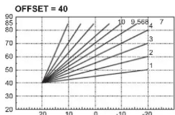
line
| x | y | | ---- | ------ | | 20 | 40 | | 10 | 50 | | 0 | 60 | | -10 | 70 | | -20 | 80 |fig. 7
line
| Date | Series 1 | Series 2 | Series 3 | Series 4 | Series 5 | Series 6 | Series 7 | Series 8 | Series 9 | Series 10 | |---|---|---|---|---|---|---|---|---|---|---| | 2010-10-20 | 30 | 30 | 30 | 30 | 30 | 30 | 30 | 30 | 30 | 30 | | (Estimated from chart center) | 40 | 45 | 50 | 55 | 60 | 65 | 70 | 75 | 80 | 85 | | (Estimated from chart center) | 45 | 50 | 55 | 60 | 65 | 70 | 75 | 80 | 85 | 90 | The chart displays a single data series with values ranging from 30 to 90. The labels above the lines represent the series numbers: 1 through 6. The chart is labeled 'Period' at the top left corner.fig. 18 - Modo TEST
- Read the warnings in this instruction booklet carefully since they provide important information on safe installation, use and maintenance.
- This instruction booklet is an integral and essential part of the product and must be kept with care by the user for future reference.
- If the unit is sold or transferred to another owner or if it is to be moved, always make sure the booklet stays with the boiler so that it can be consulted by the new owner and/or installer.
- Installation and maintenance must be carried out by professionally qualified personnel, according to current regulations and the manufacturer's instructions.
- Incorrect installation or inadequate maintenance can result in damage or injury. The manufacturer declines any liability for damage caused by errors in installation and use or by failure to follow the instructions provided.
- Before carrying out any cleaning or maintenance operation, disconnect the unit from the power supply using the system switch and/or the special cut-off devices.
-
In case of a fault and/or poor operation, deactivate the unit and do not try to repair it or directly intervene. Contact professionally qualified personnel. Any repair/replacement of the products must only be carried out by qualified personnel using genuine parts. Failure to comply with the above can compromise the safety of the unit.
-
Periodic maintenance performed by qualified personnel is essential in order to ensure proper operation of the unit.
- This unit must only be used for its intended purpose. Any other use is deemed improper and therefore hazardous.
- After unpacking, check the good condition of the contents. The packing materials are potentially hazardous and must not be left within the reach of children.
- The unit can be used by children aged at least 8 years and by persons with reduced physical, sensory or mental capabilities, or lacking experience or the necessary knowledge, only if under supervision or they have received instructions on its safe use and the related risks. Children must not play with the unit. Cleaning and maintenance intended to be done by the user can be carried out by children aged at least 8 years only if under supervision.
- In case of doubt, do not use the unit. Contact the supplier.
- The unit and its accessories must be appropriately disposed of in compliance with current regulations.
- The images given in this manual are a simplified representation of the product. In this representation there may be slight and insignificant differences with respect to the product supplied.
| This symbol indicates “CAUTION” and is placed next to all safety warnings. Strictly follow these instructions in order to avoid danger and damage to persons, animals and things | |
| This symbols calls attention to a note or important notice. | |
| This symbol, which is used on the product, packaging or documents, means that at the end of its useful life, this product must not be collected, recycled or disposed of together with domestic waste.Improper management of electric or electronic waste can lead to the leakage of hazardous substances contained in the product. For the purpose of preventing damage to health or the environment, users are kindly asked to separate this equipment from other types of waste and to ask for it to be dealt with by the municipal waste service or dealer under the conditions and according to the methods set down in national and international laws transposing the Directive 2012/19/EU.Separate waste collection and recycling of unused equipment helps to save natural resources and to guarantee that this waste is processed in a manner that is safe for health and the environment.For more information about how to collect electric and electronic equipment and appliances, please contact your local Council or Public Authority competent to issue the relevant permits. |


The CE marking certifies that the products meet the essential requirements of the relevant directives in force.
The declaration of conformity may be requested from the manufacturer.
EN
1. GENERAL WARNINGS
- Carefully read and follow the instructions contained in this instruction booklet.
• After boiler installation, inform the user regarding its operation and give him this manual, which is an integral and essential part of the product and must be kept with care for future reference.
• Installation and maintenance must be carried out by professionally qualified personnel, in compliance with the current regulations and according to the manufacturer's instructions. Do not carry out any operation on the sealed control parts. - Incorrect installation or inadequate maintenance can result in damage or injury. The Manufacturer declines any liability for damage due to errors in installation and use, or failure to follow the instructions.
- Before carrying out any cleaning or maintenance operation, disconnect the unit from the electrical power supply using the switch and/or the special cut-off devices.
- In case of a fault and/or poor operation, deactivate the unit and do not try to repair it or directly intervene. Contact professionally qualified personnel. Any repair/replacement of the products must only be carried out by qualified personnel using original replacement parts. Failure to comply with the above could affect the safety of the unit.
- This unit must only be used for its intended purpose. Any other use is deemed improper and therefore hazardous.
- The packing materials are potentially hazardous and must not be left within the reach of children.
- The unit must not be used by people (including children) with limited physical, sensory or mental abilities or without experience and knowledge of it, unless instructed or supervised in its use by someone responsible for their safety.
- The unit and its accessories must be appropriately disposed of, in compliance with the current regulations.
- The images given in this manual are a simplified representation of the product. In this representation there may be slight and insignificant differences with respect to the product supplied.
2. OPERATING INSTRUCTIONS
2.1 Introduction
Dear Customer,
Thank you for choosing a FERROLI boiler featuring advanced design, cutting-edge technology, high reliability and quality construction. Please read this manual carefully since it provides important information on safe installation, use and maintenance.
ATLAS D is a high-efficiency heat generator for domestic hot water production (optional) and heating, suitable for operation with blown oil or gas burners. The boiler shell consists of cast-iron elements, assembled with double cones and steel stays. The control system is with microprocessor and digital interface with advanced temperature control functions.

The boiler is arranged for connection to an external storage tank for hot water production (optional). In this manual all the functions relevant to domestic hot water production are only active with the optional hot water tank connected as indicated in sec. 3.3
2.2 Control panel
Panel
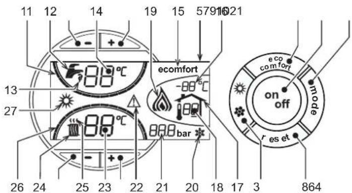
fig. 1 - Control panel
Panel - legend
1 DHW temperature setting decrease button
2 DHW temperature setting increase button
3 Heating system temperature setting decrease button
4 Heating system temperature setting increase button
5 Display
6 Summer/Winter mode selection button
7 Economy / Comfort mode selection button
8 Reset button
9 Unit On / Off button
10 "Sliding Temperature" menu button
11 Set DHW temperature reached
12 DHW symbol
13 DHW mode
14 DHW outlet temperature / setting
15 Eco (Economy) or Comfort mode
16 External sensor temperature (with optional external probe)
17 Appears on connecting the external probe or the Remote Timer Control (optionals)
18 Room temperature (with optional Remote Timer Control)
19 Burner On
20 Antifreeze operation
21 Heating system pressure
22 Fault
23 Heating delivery temperature / setting
24 Heating symbol
25 Heating mode
26 Set heating delivery temperature reached
27 Summer mode
Indication during operation
Heating
A heating demand (generated by the Room Thermostat or Remote Timer Control) is indicated by flashing of the hot air above the radiator (details 24 and 25 - fig. 1).
The heating graduation marks (detail 26 - fig. 1) light up as the heating sensor temperature reaches the set value.
fig. 2
DHW (Comfort)
A DHW demand (generated by drawing domestic hot water) is indicated by flashing of the hot water under the tap (details 12 and 13 - fig. 1). Make sure the Comfort function (detail 15 - fig. 1) is activated
The DHW graduation marks (detail 11 - fig. 1) light up as the DHW sensor temperature reaches the set value.
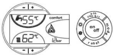
fig. 3
Exclude hot water storage tank (economy)
Hot water tank temperature maintaining/heating can be excluded by the user. If excluded, domestic hot water will not be delivered.
When hot water tank heating is on (default setting), the COMFORT symbol (detail 15 - fig. 1) is activated on the display; whereas when off, the ECO symbol (detail 15 - fig. 1) is activated
The hot water tank can be deactivated by the user (ECO mode) by pressing the eco/comfort button (detail 7 - fig. 1). To activate the COMFORT mode, press the eco/comfort button (detail 7 - fig. 1) again.
2.3 Lighting and turning off
Boiler not electrically powered
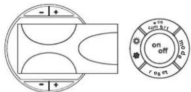
fig. 4 - Boiler not electrically powered
The antifreeze system does not work when the power and/or gas to the unit are turned off. To avoid damage caused by freezing during long idle periods in winter, it is advisable to drain all water from the boiler, DHW circuit and system; or drain just the DHW circuit and add a suitable antifreeze to the heating system, complying with that prescribed in sec. 3.3.
Boiler lighting
- Open the fuel on-off valves.
- Switch on the power to the unit.
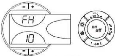
fig. 5 - Boiler lighting
- For the following 120 seconds the display will show FH which identifies the heating system air venting cycle.
- During the first 5 seconds the display will also show the card software version.
- When the message FH disappears, the boiler is ready to operate automatically whenever domestic hot water is drawn or in case of a room thermostat demand.
Turning the boiler off
Press the on/off button (detail 9 - fig. 1) for 1 second.

fig. 6 - Turning the boiler off
When the boiler is turned off, the PCB is still powered.
Domestic hot water and heating are disabled. The antifreeze system remains activated.
To relight the boiler, press the on/off button (detail 9 fig. 1) again for 1 second.
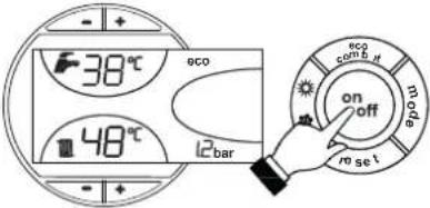
fig. 7
The boiler will be immediately ready to operate whenever domestic hot water is drawn or in case of a room thermostat demand.
2.4 Adjustments
Summer/Winter Switchover
Press the summer/winter button (detail 6 - fig. 1) for 1 second.
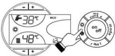
fig. 8
The display activates the Summer symbol (detail 27 - fig. 1): the boiler will only deliver domestic hot water. The antifreeze system remains activated.
To deactivate the Summer mode, press the summer/winter button (part. 6 - fig. 1) again for 1 second.
Heating temperature setting
Use the heating buttons (details 3 and 4 - fig. 1) to adjust the temperature from a min. of 30^ C to a max. of 80^ C.
In any case it is advisable not to operate the boiler below 45°C.
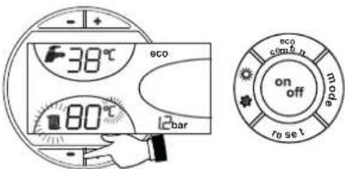
fig. 9
DHW temperature adjustment
Use the DHW buttons -/+ (details 1 and 2 - fig. 1) to adjust the temperature from a min. of 10^ C to a max. of 65^ C.
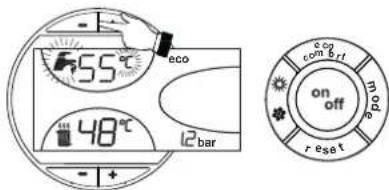
fig. 10
Room temperature adjustment (with optional room thermostat)
Using the room thermostat, set the temperature desired in the rooms. If the room thermostat is not installed the boiler will keep the heating system at its setpoint temperature.
Room temperature adjustment (with optional remote timer control)
Using the remote timer control, set the temperature desired in the rooms. The boiler unit will set the system water according to the required room temperature. For information on the remote timer control, please refer to its user's manual.
Sliding temperature
When the optional external probe is installed the control panel display (detail 5 - fig. 1) shows the actual outside temperature read by the probe. The boiler control system operates with "Sliding Temperature". In this mode, the temperature of the heating system is adjusted according the outside weather conditions, in order to ensure high comfort and energy saving throughout the year. In particular, as the outside temperature increases, the system delivery temperature is decreased according to a specific "compensation curve".
With Sliding Temperature adjustment, the temperature set with the heating buttons -/+ (details 3 and 4 - fig. 1) becomes the maximum system delivery temperature. It is advisable to set a maximum value to allow system adjustment throughout its useful operating range.
The boiler must be adjusted at the time of installation by qualified personnel. Possible adjustments can in any case be made by the user to improve comfort.
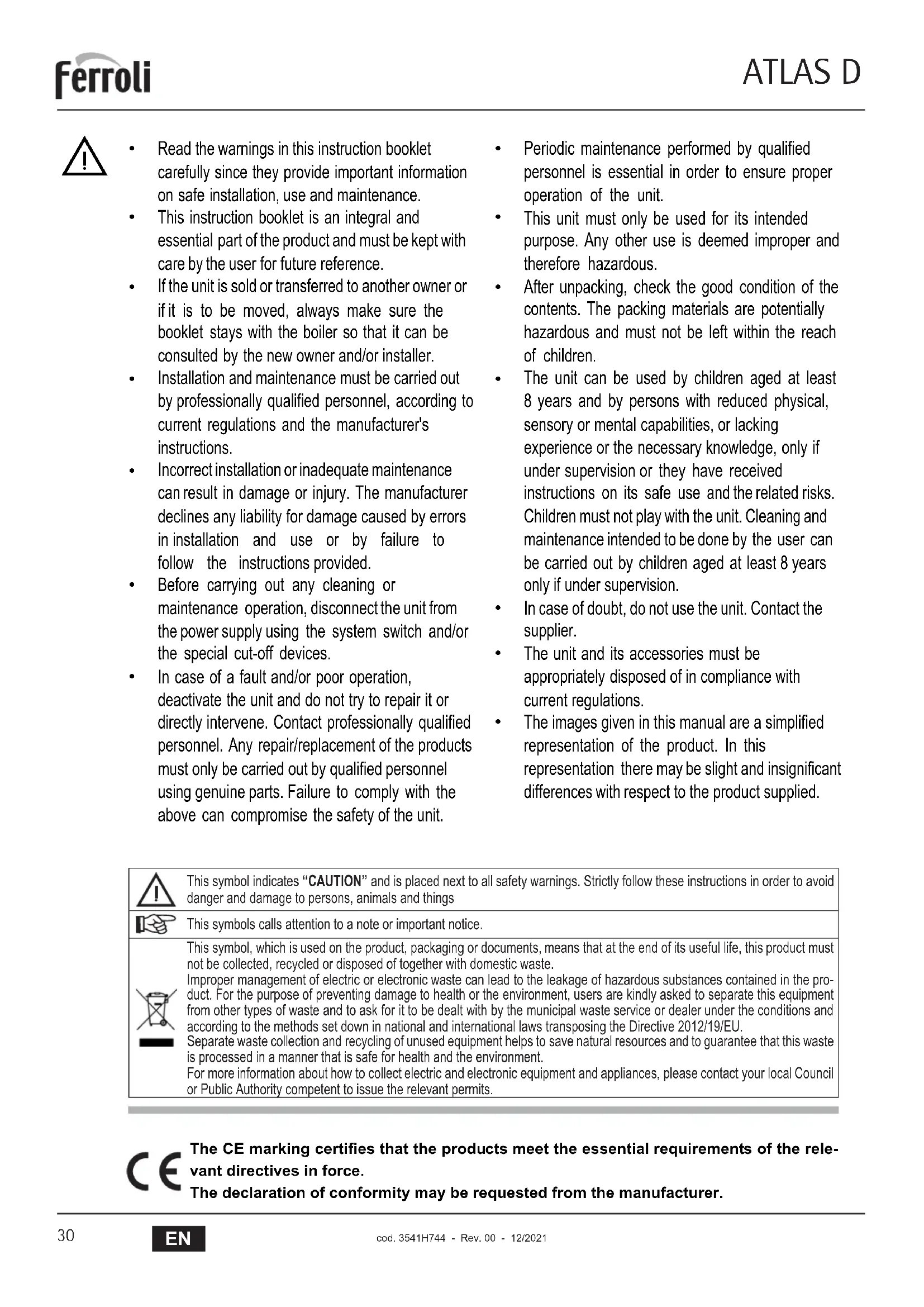
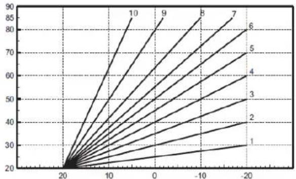
Compensation curve and curve offset
Press the mode button (detail 10 - fig. 1) once to display the actual compensation curve (fig. 11), which can be modified with the DHW buttons (details 1 and 2 - fig. 1).
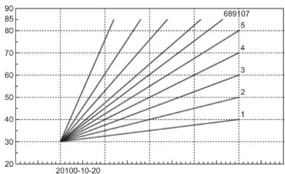
Adjust the required curve from 1 to 10 according to the characteristic (fig. 13).
By setting the curve to 0, sliding temperature adjustment is disabled.
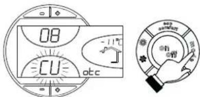
fig. 11 - Compensation curve
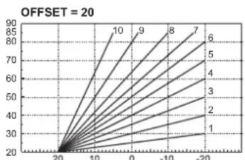
Press the heating buttons (details 3 and 4 - fig. 1) to access parallel curve offset (fig. 14), modifiable with the DHW buttons (details 1 and 2 - fig. 1).
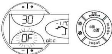
fig. 12 - Curve parallel offset
Press the mode button (detail 10 - fig. 1) again to exit parallel curve adjustment mode.
If the room temperature is lower than the required value, it is advisable to set a higher order curve and vice versa. Proceed by increasing or decreasing in steps of one and check the result in the room.
line
| X-axis Label | Series 1 | Series 2 | Series 3 | Series 4 | Series 5 | Series 6 | Series 7 | Series 8 | Series 9 | Series 10 | |---|---|---|---|---|---|---|---|---|---|---| | 20100-10-20 | 30 | 30 | 30 | 30 | 30 | 30 | 30 | 30 | 30 | 30 | | (Data not extractable as discrete values; chart displays multiple lines and labels) | | | | | | | | | | |fig. 13 - Compensation curves
line
| x | y | |----|------| | 0 | 0 | | -20| 30 |fig. 14 - Example of compensation parallel curve offset

line
| x | y | |----|------| | 20 | 40 | | 10 | 85 | | 0 | 90 | | -10| 75 | | -20| 60 |Adjustments from Remote Timer Control

If the Remote Timer Control (optional) is connected to the boiler, the above adjustments are managed according to that given in table 1. Also, the control panel display (detail 5 - fig. 1) shows the actual room temperature detected by the Remote Timer Control.
Table. 1
| Heating temperature setting | Adjustment can be made from the Remote Timer Control menu and the boiler control panel. |
| DHW temperature adjustment | Adjustment can be made from the Remote Timer Control menu and the boiler control panel. |
| Summer/Winter Switchover | Summer mode has priority over a possible Remote Timer Control heating demand. |
| Eco/Comfort selection | On disabling DHW from the Remote Timer Control menu, the boiler selects the Economy mode. In this condition, thebutton 7 - fig. 1 on the boiler panel is disabled. |
| On enabling DHW from the Remote Timer Control menu, the boiler selects the Comfort mode. In this condition it is possible select one of the two modes with thebutton 7 - fig. 1 on the boiler panel. | |
| Sliding Temperature | Both the Remote Timer Control and the boiler card manage Sliding Temperature adjustment: of the two, the Sliding Temperature of the boiler card has priority. |
Water system pressure adjustment
The filling pressure with system cold, read on the display, must be approx. 1.0 bar. If the system pressure falls to values below minimum, the boiler card will activate fault F37 (fig. 15).
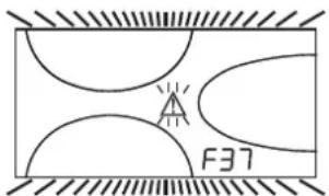
fig. 15 - Low system pressure fault

Once the system pressure is restored, the boiler will activate the 120-second air venting cycle indicated on the display by FH.
3. INSTALLATION
3.1 General Instructions
BOILER INSTALLATION MUST ONLY BE PERFORMED BY QUALIFIED PERSONNEL, IN ACCORDANCE WITH ALL THE INSTRUCTIONS GIVEN IN THIS TECHNICAL MANUAL, THE PROVISIONS OF CURRENT LAW, THE PRESCRIPTIONS OF NATIONAL AND LOCAL STANDARDS AND THE RULES OF PROPER WORKMANSHIP.
3.2 Place of installation
The boiler must be installed in a special room with ventilation openings towards the outside in conformity with current regulations. If there are several burners or extraction units that can work together in the same room, the ventilation openings must be sized for simultaneous operation of all the units. The place of installation must be free of flammable objects or materials, corrosive gases, volatile substances or dusts which, sucked by the burner fan, can obstruct the pipes inside the burner or the combustion head. The room must be dry and not exposed to rain, snow or frost.

If the unit is enclosed in a cabinet or mounted alongside, a space must be provided for removing the casing and for normal maintenance operations. In particular, after boiler installation with burner on the front door, make sure the front door can open freely without the burner striking walls or other obstacles.
3.3 Plumbing connections
The heating capacity of the unit must be previously established by calculating the building's heat requirement according to the current regulations. The system must be provided with all the components for correct and regular operation. It is advisable to install shutoff valves between the boiler and heating system allowing the boiler to be isolated from the system if necessary.

The safety valve outlet must be connected to a funnel or collection pipe to prevent water spurting onto the floor in case of overpressure in the heating circuit. Otherwise, if the discharge valve cuts in and floods the room, the boiler manufacturer cannot be held liable.
Do not use the water system pipes to earth electrical appliances.
Before installation, carefully wash all the pipes of the system to remove any residuals or impurities that could affect proper operation of the unit.
Carry out the relevant connections according to the diagram in and thecap. 5 symbols given on the unit.
Water system characteristics
In the presence of water harder than 25^ Fr ( 1^ F = 10ppm CaCO _3 ), use suitably treated water in order to avoid possible scaling in the boiler. Treatment must not reduce the hardness to values below 15^ F (Decree 236/88 for uses of water intended for human consumption). Treatment of the water used is indispensable in case of very large systems or with frequent introduction of replenishing water in the system.

If water softeners are installed at the boiler cold water inlet, make sure not to reduce the water hardness too much, as this could cause early deterioration of the magnesium anode in the hot water tank.
Antifreeze system, antifreeze fluids, additives and inhibitors
The boiler is equipped with an antifreeze system that turns on the boiler in heating mode when the system delivery water temperature falls under 6^ C. The device will not come on if the electricity and/or gas supply to the unit are cut off. If it becomes necessary, it is permissible to use antifreeze fluid, additives and inhibitors only if the manufacturer of these fluids or additives guarantees they are suitable for this use and cause no damage to the heat exchanger or other components and/or materials of the boiler unit and system. It is prohibited to use generic antifreeze fluid, additives or inhibitors that are not expressly suited for use in heating systems and compatible with the materials of the boiler unit and system.
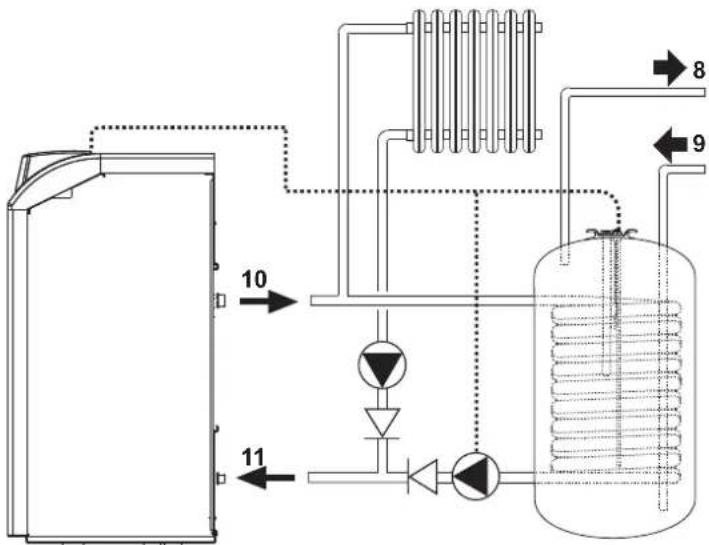
Connection to a storage tank for domestic hot water production
The unit's electronic board is arranged for managing an external storage tank for domestic hot water production. Carry out the plumbing connections according to the diagram fig. 16 (pumps and non- return valves must be supplied separately). Carry out: electrical connections as shown in the wiring diagram in cap. 5.4. A probe must be used FERROLI. At the next lighting, the boiler's control system recognises the presence of the hot water tank probe and automatically configures the DHW function, activating the display and relevant controls.
flowchart
graph TD
    A["Input 10"] --> B["Reactor Unit"]
    C["Input 11"] --> B
    B --> D["Reactor Unit"]
    D --> E["Output 8"]
    D --> F["Output 9"]
    D --> G["Output 10"]
    style A fill:#f9f,stroke:#333
    style C fill:#f9f,stroke:#333
    style E fill:#ccf,stroke:#333
    style F fill:#ccf,stroke:#333
    style G fill:#ccf,stroke:#333
fig. 16 - Diagram of connection to external hot water tank
Key
8 Domestic hot water outlet
9 Domestic cold water inlet
10 System delivery
11 System return
3.4 Burner connection
The oil burner, with blown air for pressurized furnaces, can be used if its operation characteristics are suitable for the size of the boiler furnace and its overpressure. The choice of burner must be made beforehand, following the manufacturer's instructions, according to the work range, fuel consumption and pressures, as well as the length of the combustion chamber. Install the burner according to the Manufacturer's instructions.

The electrical power absorbed by the burner must not exceed the value given in the technical data table.
3.5 Electrical connections
Connection to the electrical grid

The unit's electrical safety is only guaranteed when correctly connected to an efficient earthing system executed according to current safety standards. Have the efficiency and suitability of the earthing system checked by professionally qualified personnel. The manufacturer is not responsible for any damage caused by failure to earth the system. Also make sure that the electrical system is adequate for the maximum power absorbed by the unit, as specified on the boiler dataplate.
The boiler is prewired and provided with a Y-cable and plug for connection to the electricity line. The connections to the grid must be made with a permanent connection and equipped with a bipolar switch whose contacts have a minimum opening of at least 3 mm, interposing fuses of max. 3A between the boiler and the line. It is important to respect the polarities (LINE: brown wire / NEUTRAL: blue wire / EARTH: yellow-green wire) in making connections to the electrical line. During installation or when changing the power cable, the earth wire must be left 2 cm longer than the others.

The user must never change the unit's power cable. If the cable gets damaged, switch off the unit and have it changed solely by professionally qualified personnel. If changing the electric power cable, use solely "HAR H05 VV-F" 3x0.75 mm2 cable with a maximum outside diameter of 8 mm.
Room thermostat (optional)

IMPORTANT: THE ROOM THERMOSTAT MUST HAVE VOLTAGE-FREE CONTACTS. CONNECTING 230 V TO THE ROOM THERMOSTAT TERMINALS WILL PERMANENTLY DAMAGE THE ELECTRONIC BOARD.
When connecting time controls or a timer, do not take the power supply for these devices from their breaking contacts Their power supply must be by means of direct connection from the mains or with batteries, depending on the kind of device.
Accessing the electrical terminal block
Undo the two screws "A" located on the top part of the control panel and remove the cover.
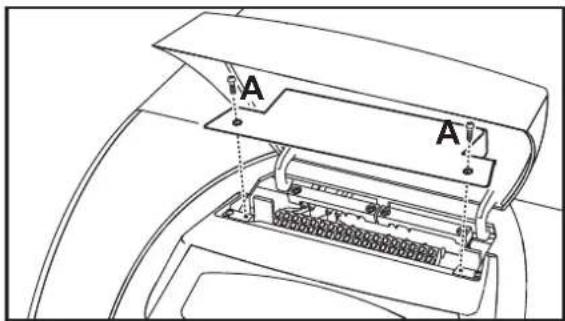
fig. 17 - Accessing the terminal board
3.6 Connection to the flue
The unit must be connected to a flue designed and built in compliance with current regulations. The pipe between the boiler and flue must be made from material suitable for the purpose, i.e. heat and corrosion resistant. Ensure the seal at the joints and insulate the entire pipe between boiler and flue, to prevent the formation of condensate.
4. SERVICE AND MAINTENANCE
All adjustment, conversion, commissioning and maintenance operations described below must only be carried out by Qualified Personnel (meeting the professional technical requirements of current regulations) such as the personnel of the Local After-Sales Technical Service.
FERROLI declines any liability for damage and/or injury caused by unqualified and unauthorised persons tampering with the unit.
4.1 Adjustments
TEST mode activation
Press the heating buttons (details 3 and 4 - fig. 1) together for 5 seconds to activate the TEST mode. The boiler switches on irrespective of the system or DHW request.
The heating symbol (detail 24 - fig. 1) and DHW symbol (detail 12 - fig. 1) flash on the display.
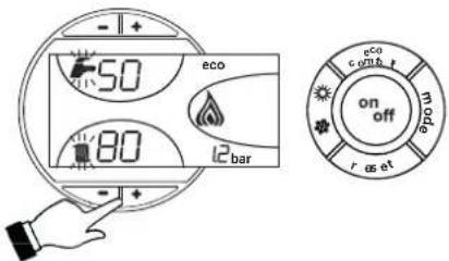
fig. 18 - TEST mode
To deactivate the TEST mode, repeat the activation sequence.
The TEST mode is deactivated automatically in any case after 15 minutes.
Burner adjustment
Boiler efficiency and correct operation depend above all on accurate burner adjustments. Carefully follow the Manufacturer's instructions. The two-stage burners must have the first stage adjusted to a power level not below the boiler's rated min. power. The power of the second stage must not be higher than the boiler's rated max. power.
4.2 Start-up

Checks to be made at first lighting, and after all maintenance operations that involved disconnecting from the systems or an intervention on safety devices or parts of the boiler:
Before lighting the boiler
- Open any on-off valves between the boiler and the systems.
- Check the seal of the fuel system.
- Check correct prefilling of the expansion tank.
- Fill the water system and make sure that all air contained in the boiler and the system has been vented, by opening the air valve on the boiler and any air valves on the system.
- Make sure there are no water leaks in the system, domestic hot water circuits, connections or boiler.
- Check correct connection of the electrical system and efficiency of the earthing system
- Make sure there are no flammable liquids or materials in the immediate vicinity of the boiler
Checks during operation
- Turn the unit on as described in sec. 2.3.
- Check the seal of the fuel circuit and water systems.
- Check the efficiency of the flue and air-fume ducts during boiler operation.
• Make sure the water is circulating properly between the boiler and systems. - Check correct boiler lighting by performing various tests, turning it on and off with the room thermostat or remote control.
- Make sure the fuel consumption indicated on the meter matches that given in the technical data table on sec. 5.3.
- Ensure the seal of the fumebox and burner door.
- Make sure the burner works properly. This check must be made with the special instruments, following the manufacturer's instructions.
- Check correct programming of the parameters and carry out any required customisation (compensation curve, power, temperatures, etc.).
4.3 Maintenance
Periodical check
To ensure proper operation of the unit over time, have qualified personnel carry out a yearly inspection, providing for the following checks:
• The control and safety devices must work properly.
• The fume exhaust circuit must be perfectly efficient.
- Check there are no obstructions or dents in the fuel supply and return pipes.
- Clean the fuel suction line filter.
• Measure the correct fuel consumption
- Clean the combustion head in the fuel outlet zone, on the swirl disc.
- Leave the burner on at full capacity for about ten minutes, then analyze the combustion, checking:
- Correct calibration of all the elements specified in this manual
- Temperatures of the fumes at the flue
- CO2 percentage content
• The fume ducts must be free of obstructions and leaks
- The burner and exchanger must be clean and free of deposits. For possible cleaning do not use chemical products or wire brushes.
• The gas and water systems must be tight.
- The water pressure in the system when cold must be approx. 1 bar; otherwise bring it to that value.
• The circulating pump must not be blocked.
• The expansion tank must be filled.
- Check the magnesium anode and replace it if necessary.

The boiler casing, control panel and aesthetic parts can be cleaned with a soft and damp cloth, if necessary soaked in soapy water. Do not use abrasive detergents and solvents.
Boiler cleaning
- Disconnect the power supply to the boiler.
- Remove the front top and bottom panel.
- Open the door by undoing the knobs.
- Clean the inside of the boiler and the entire path of exhaust fumes, using a tube brush or compressed air.
- Then close the door, securing it with the knob.
To clean the burner, refer to the Manufacturer's instructions.
4.4 Troubleshooting
Diagnostics
The boiler is equipped with an advanced self-diagnosis system. In case of a boiler fault, the display will flash together with the fault symbol (detail 22 - fig. 1) indicating the fault code.
There are faults that cause permanent shutdowns (marked with the letter "A"): to restore operation press the RESET button (detail 8 - fig. 1) for 1 second or use the RESET on the remote timer control (optional) if installed; if the boiler does not restart it is necessary to eliminate the fault indicated in the operation LEDs.
Other faults cause temporary shutdowns (marked with the letter "F") which are automatically reset as soon as the value returns within the boiler's normal working range.
Table. 2 - List of faults
| Fault code | Fault Possible cause Cure | ||
| A01 | Burner block (RESET OCCURS ONLY ON THE BURNER) | Refer to the burner manual | |
| A02 | Card parameter fault Wrong card parameter setting | Check the card parameter and modify it if necessary | |
| A03 | Overtemperature protection activation | Heating sensor damaged | Check the correct positioning and operation of the heating sensor |
| No water circulation in the system Ch | Check the circulating pump | ||
| Air in the system Vent the system | |||
| A04 | Card parameter fault Wrong card parameter setting | Check the card parameter and modify it if necessary | |
| F07 | Wiring fault Connector X5 not connected Check the wiring | ||
| F09 | Card parameter fault Wrong card parameter setting | Check the card parameter and modify it if necessary | |
| F10 | Delivery sensor 1 fault | Sensor damaged | Check the wiring or replace the sensor Wiring shor |
| Wiring disconnected | |||
| F11 | DHW sensor fault | Sensor damaged | Check the wiring or replace the sensor Wiring shor |
| Wiring disconnected | |||
| F12 | Card parameter fault Wrong card parameter setting | Check the card parameter and modify it if necessary | |
| F13 | Wiring fault Connector X12 not connected Check the wiring | ||
| F14 | Delivery sensor 2 fault | Sensor damaged | Check the wiring or replace the sensor Wiring shor |
| Wiring disconnected | |||
| F16 | Card parameter fault Wrong card parameter setting | Check the card parameter and modify it if necessary | |
| F34 | Supply voltage under 170V. | Electric mains trouble | Check the electrical system |
| F35 | Faulty mains frequency | Electric mains trouble | Check the electrical system |
| F37 | Incorrect system water pres- sure | Pressure too low | Fill the system |
| Sensor damaged | Check the sensor | ||
| F39 | External probe fault | Probe damaged or wiring shorted | Check the wiring or replace the sensor |
| Probe disconnected after activating the sliding temperature | Reconnect the external probe or disable the sliding temperature | ||
| F40 | Incorrect system water pressure | Pressure too high | Check the system |
| Check the safety valve | |||
| Check the expansion tank | |||
| A41 | Sensor positioning | Delivery sensor not inserted in boiler shell | Check the correct positioning and operation of the heating sensor |
| F42 | Heating sensor fault | Sensor damaged | Replace the sensor |
| F47 | System water pressure sensor fault | Wiring disconnected | Check the wiring |
5. TECHNICAL DATA AND CHARACTERISTICS
5.1 Dimensions, connections and main components
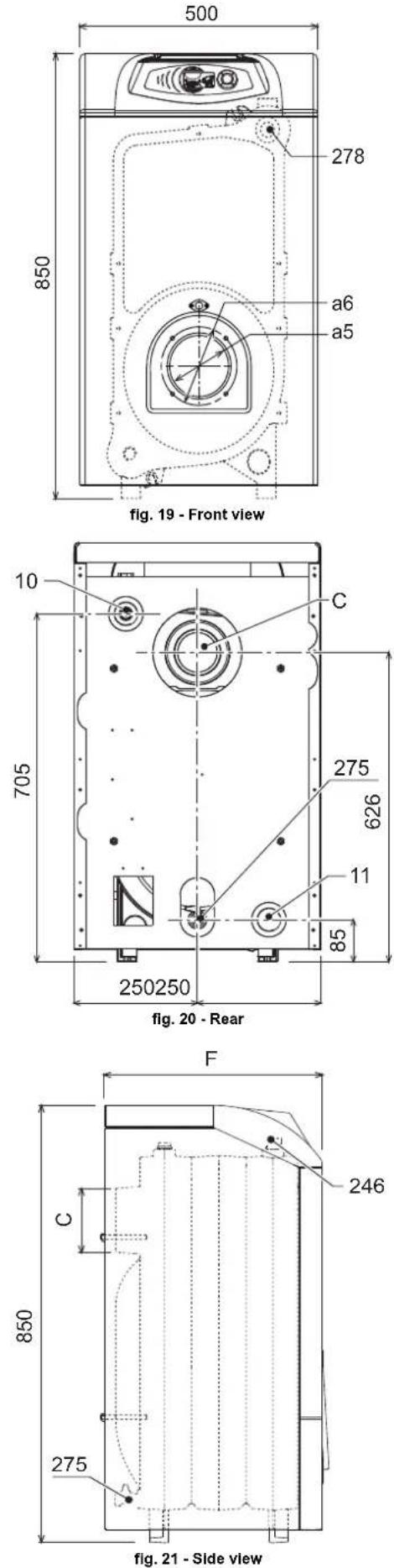
| C∅ mm | Fmm | a5∅ mm | a6∅ mm | |
| ATLAS D 25 | 120÷130 400 115 | 150 | ||
| ATLAS D 37 | 120÷130 500 115 | 150 | ||
| ATLAS D 50 | 120÷130 600 115 | 150 | ||
| ATLAS D 63 | 120÷130 700 115 | 150 | ||
| ATLAS D 75 | 120÷130 800 115 | 150 |
10 System delivery 1" 1/2"
11 System return 1" 1/2"
246 Pressure transducer
275 Heating system drain cock
278 Double sensor (heating + safety)
a5 Burner hole
a6 Burner connection
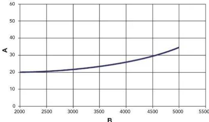
5.2 Loss of head
Pressure loss water side
line
| B | A | | ---- | --- | | 2000 | 20 | | 2500 | 21 | | 3000 | 22 | | 3500 | 24 | | 4000 | 26 | | 4500 | 29 | | 5000 | 34 |fig. 22 - Pressure loss
A mbar
B Flowrate l/h
5.3 Technical data table
| Data | Unit | Value | Value | Value | Value | Value | |
| Model ATLASD | 25 | ATLASD 37 | ATLASD 50 | ATLASD 63 | ATLASD 75 | ||
| Number of elements | no. | 3 | 4 | 5 | 6 | 7 | |
| Max. heating capacity | kW | 28.3 | 41.9 | 56.6 | 71.3 | 84.6 | (Q) |
| Min. heating capacity | kW | 22.4 | 22.3 | 33.4 | 44.5 | 55.8 | (Q) |
| Max. heat output in heating | kW | 25 | 37 | 50 | 63 | 75 | (P) |
| Min. heat output in heating | kW | 20 | 20 | 30 | 40 | 50 | (P) |
| Efficiency Pmax (80-60°C) | % | 88.2 | 88.3 | 88.4 | 88.4 | 88.7 | |
| Efficiency 30% | % | 92.2 | 91.7 | 91.4 | 91.0 | 90.5 | |
| Efficiency class Directive 92/42 EEC | ★★★ | ||||||
| Max. working pressure in heating | bar | 6 | 6 | 6 | 6 | 6 | (PMS) |
| Min. working pressure in heating | bar | 0.8 | 0.8 | 0.8 | 0.8 | 0.8 | |
| Max. heating temperature | °C | 100 | 100 | 100 | 100 | 100 | (tmax) |
| Heating water content | L | 18 | 23 | 28 | 33 | 38 | |
| Protection rating | IP | XOD | XOD | XOD | XOD | XOD | |
| Power supply voltage | V/Hz | 230/50 | 230/50 | 230/50 | 230/50 | 230/50 | |
| Electrical power input | W3 | 3 | 3 | 3 | 3 | ||
| Burner MAX power input | W | 170 | 180 | 230 | 250 | 250 | |
| Empty weight | kg | 127 | 166 | 205 | 244 | 283 | |
| Combustion chamber length | mm | 350 | 450 | 550 | 650 | 750 | |
| Combustion chamber diameter | mm | 300 | 300 | 300 | 300 | 300 | |
| Pressure loss on fume side | mbar | 0.11 | 0.35 | 0.38 | 0.5 | 0.6 | |
ErP product fiche
MODEL: ATLAS D 25 - (OIHJ3PWA)
| Trademark: FERROLI | |||
| Condensing boiler: NO | |||
| Low-temperature boiler (**): YES | |||
| B1 Boiler: NO | |||
| Combination heater: NO | |||
| Cogeneration space heater: NO | |||
| Item | Symbol | Unit | Value |
| Seasonal space heating energy efficiency class (from A+++ to D) | B | ||
| Rated heat output | Pn | kW | 25 |
| Seasonal space heating energy efficiency | _s | % | 86 |
| Useful heat out put | |||
| Useful heat output at rated heat output and high-temperature regime (*) | P4 | kW | 25,0 |
| Useful heat output at 30% of rated heat output and low-temperature regime (**) | P1 | kW | 7,8 |
| Useful efficiency | |||
| Useful efficiency at rated heat output and high-temperature regime (*) | _4 | % | 88,2 |
| Useful efficiency at 30% of rated heat output and low-temperature regime (**) | _1 | % | 92,2 |
| Auxiliary electricity consumption | |||
| At full load | elmax | kW | 0,150 |
| At part load | elmin | kW | 0,069 |
| In standby mode | PSB | kW | 0,003 |
| Other items | |||
| Standby heat loss | Pstby | kW | 0,105 |
| Ignition burner power consumption | Pign | kW | 0,000 |
| Annual energy consumption | QHE | GJ | 83 |
| Sound power level | LWA | dB | 66 |
| Emissions of nitrogen oxides | NOx | mg/kWh | 139 |
(*) High-temperature regime means 60°C return temperature at heater inlet and 80°C feed temperature at heater outlet.
(**) Low temperature means for condensing boilers 30°C, for low-temperature boilers 37°C and for other heaters 50°C return temperature (at heater inlet).
Values obtained with burner FERROLI "SUN G3"
ErP product fiche
MODEL: ATLAS D 37 - (OIHJ4PWA)
| Trademark: FERROLI | |||
| Condensing boiler: NO | |||
| Low-temperature boiler (**): YES | |||
| B1 Boiler: NO | |||
| Combination heater: NO | |||
| Cogeneration space heater: NO | |||
| Item | Symbol | Unit | Value |
| Seasonal space heating energy efficiency class (from A+++ to D) | B | ||
| Rated heat output | Pn | kW | 37 |
| Seasonal space heating energy efficiency | _s | % | 86 |
| Useful heat out put | |||
| Useful heat output at rated heat output and high-temperature regime (*) | P4 | kW | 37,1 |
| Useful heat output at 30% of rated heat output and low-temperature regime (**) | P1 | kW | 11,5 |
| Useful efficiency | |||
| Useful efficiency at rated heat output and high-temperature regime (*) | _4 | % | 88,3 |
| Useful efficiency at 30% of rated heat output and low-temperature regime (**) | _1 | % | 91,5 |
| Auxiliary electricity consumption | |||
| At full load | elmax | kW | 0,150 |
| At part load | elmin | kW | 0,068 |
| In standby mode | PSB | kW | 0,003 |
| Other items | |||
| Standby heat loss | Pstby | kW | 0,127 |
| Ignition burner power consumption | Pign | kW | 0,000 |
| Annual energy consumption | QHE | GJ | 123 |
| Sound power level | LWA | dB | 66 |
| Emissions of nitrogen oxides | NOx | mg/kWh | 119 |
(*) High-temperature regime means 60°C return temperature at heater inlet and 80°C feed temperature at heater outlet.
(**) Low temperature means for condensing boilers 30°C, for low-temperature boilers 37°C and for other heaters 50°C return temperature (at heater inlet).
Values obtained with burner FERROLI "SUN G6"
ErP product fiche
MODEL: ATLAS D 50 - (OIHJ5PWA)
| Trademark: FERROLI | |||
| Condensing boiler: NO | |||
| Low-temperature boiler (**): YES | |||
| B1 Boiler: NO | |||
| Combination heater: NO | |||
| Cogeneration space heater: NO | |||
| Item | Symbol | Unit | Value |
| Seasonal space heating energy efficiency class (from A+++ to D) | B | ||
| Rated heat output | Pn | kW | 50 |
| Seasonal space heating energy efficiency | _s | % | 87 |
| Useful heat out put | |||
| Useful heat output at rated heat output and high-temperature regime (*) | P4 | kW | 50,1 |
| Useful heat output at 30% of rated heat output and low-temperature regime (**) | P1 | kW | 15,5 |
| Useful efficiency | |||
| Useful efficiency at rated heat output and high-temperature regime (*) | _4 | % | 88,4 |
| Useful efficiency at 30% of rated heat output and low-temperature regime (**) | _1 | % | 91,4 |
| Auxiliary electricity consumption | |||
| At full load | elmax | kW | 0,200 |
| At part load | elmin | kW | 0,068 |
| In standby mode | PSB | kW | 0,003 |
| Other items | |||
| Standby heat loss | Pstby | kW | 0,150 |
| Ignition burner power consumption | Pign | kW | 0,000 |
| Annual energy consumption | QHE | GJ | 166 |
| Sound power level | LWA | dB | 67 |
| Emissions of nitrogen oxides | NOx | mg/kWh | 115 |
(*) High-temperature regime means 60°C return temperature at heater inlet and 80°C feed temperature at heater outlet.
(**) Low temperature means for condensing boilers 30°C, for low-temperature boilers 37°C and for other heaters 50°C return temperature (at heater inlet).
Values obtained with burner FERROLI "SUN G10"
ErP product fiche
MODEL: ATLAS D 63 - (OIHJ6PWA)
| Trademark: FERROLI | |||
| Condensing boiler: NO | |||
| Low-temperature boiler (**): YES | |||
| B1 Boiler: NO | |||
| Combination heater: NO | |||
| Cogeneration space heater: NO | |||
| Item | Symbol | Unit | Value |
| Seasonal space heating energy efficiency class (from A+++ to D) | B | ||
| Rated heat output | Pn | kW | 63 |
| Seasonal space heating energy efficiency | _s | % | 86 |
| Useful heat out put | |||
| Useful heat output at rated heat output and high-temperature regime (*) | P4 | kW | 63,0 |
| Useful heat output at 30% of rated heat output and low-temperature regime (**) | P1 | kW | 19,4 |
| Useful efficiency | |||
| Useful efficiency at rated heat output and high-temperature regime (*) | _4 | % | 88,4 |
| Useful efficiency at 30% of rated heat output and low-temperature regime (**) | _1 | % | 90,8 |
| Auxiliary electricity consumption | |||
| At full load | elmax | kW | 0,198 |
| At part load | elmin | kW | 0,066 |
| In standby mode | PSB | kW | 0,003 |
| Other items | |||
| Standby heat loss | Pstby | kW | 0,175 |
| Ignition burner power consumption | Pign | kW | 0,000 |
| Annual energy consumption | QHE | GJ | 210 |
| Sound power level | LWA | dB | 69 |
| Emissions of nitrogen oxides | NOx | mg/kWh | 113 |
(*) High-temperature regime means 60°C return temperature at heater inlet and 80°C feed temperature at heater outlet.
(**) Low temperature means for condensing boilers 30°C, for low-temperature boilers 37°C and for other heaters 50°C return temperature (at heater inlet).
Values obtained with burner FERROLI "SUN G10"
ErP product fiche
MODEL: ATLAS D 75 - (0IHJ7PWA)
| Trademark: FERROLI | |||
| Condensing boiler: NO | |||
| Low-temperature boiler (**): YES | |||
| B1 Boiler: NO | |||
| Combination heater: NO | |||
| Cogeneration space heater: NO | |||
| Item | Symbol | Unit | Value |
| Rated heat output | Pn | kW | 75 |
| Seasonal space heating energy efficiency | _s | % | 86 |
| Useful heat out put | |||
| Useful heat output at rated heat output and high-temperature regime (*) | P4 | kW | 75,1 |
| Useful heat output at 30% of rated heat output and low-temperature regime (**) | P1 | kW | 23,0 |
| Useful efficiency | |||
| Useful efficiency at rated heat output and high-temperature regime (*) | _4 | % | 88,7 |
| Useful efficiency at 30% of rated heat output and low-temperature regime (**) | _1 | % | 90,5 |
| Auxiliary electricity consumption | |||
| At full load | elmax | kW | 0,195 |
| At part load | elmin | kW | 0,065 |
| In standby mode | PSB | kW | 0,003 |
| Other items | |||
| Standby heat loss | Pstby | kW | 0,200 |
| Ignition burner power consumption | Pign | kW | 0,000 |
| Annual energy consumption | QHE | GJ | 250 |
| Sound power level | LWA | dB | 70 |
| Emissions of nitrogen oxides | NOx | mg/kWh | 110 |
(*) High-temperature regime means 60°C return temperature at heater inlet and 80°C feed temperature at heater outlet.
(**) Low temperature means for condensing boilers 30°C, for low-temperature boilers 37°C and for other heaters 50°C return temperature (at heater inlet).
Values obtained with burner FERROLI "SUN G10"
5.4 Wiring diagram

fig. 23 - Wiring diagram
32 Heating circulating pump (optional)
42 DHW temperature probe (optional)
72 Room thermostat (optional)
130 DHW circulating pump (optional)
138 External probe (optional)
139 Remote timer control (optional)
211 Burner connector
246 Pressure transducer
278 Double sensor (heating + safety)
304 Stage 2 burner connector (only version with 6 and 7 elements)

fig. 2
fig. 3
fig. 7
fig. 8
line
OFFSET = 20 | X-axis | Series 1 | Series 2 | Series 3 | Series 4 | Series 5 | Series 6 | Series 7 | Series 8 | Series 9 | Series 10 | |---|---|---|---|---|---|---|---|---|---|---| | -20 | 20 | 20 | 20 | 20 | 20 | 20 | 20 | 20 | 20 | 20 | | -10 | 30 | 35 | 40 | 45 | 50 | 55 | 60 | 65 | 70 | 75 | | 0 | 40 | 45 | 50 | 55 | 60 | 65 | 70 | 75 | 80 | 85 | | 10 | 50 | 55 | 60 | 65 | 70 | 75 | 80 | 85 | 90 | 95 | | 20 | 60 | 65 | 70 | 75 | 80 | 85 | 90 | 95 | 100 | 105 | The chart displays a single data series with no explicit title or axis labels. The values for each series are explicitly labeled on the chart.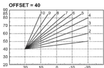
line
| x | y | |----|------| | 20 | 40 | | 10 | 85 | | 0 | 90 | | -10| 75 | | -20| 60 |fig. 18 - Mode TEST
MODÈLE: ATLAS D 25 - (0IHJ3PWA)
MODÈLE: ATLAS D 75 - (0IHJ7PWA)
ALGEMENE WAARSCHUWINGEN
1. ALGEMENE WAARSCHUWINGEN
Sanitair water (Comfort)
fig. 3
Uitschakeling boiler (economy)
fig. 5 - Aanzetten verwarmingsketel
fig. 6 - Uitschakelen verwarmingsketel
fig. 7
fig. 8
рис. 2
рис. 7
рис. 8
line
| X | Y | |---|---| | 20 | 30 | | -20 | 40 | | -10 | 50 | | -5 | 60 | | 0 | 70 | | 5 | 80 | | 10 | 90 | The chart displays a series of lines labeled 1 through 10, with each line representing a separate data series. The x-axis ranges from -20 to 20, and the y-axis ranges from 20 to 90. No explicit title or axis labels are provided in the image.εικ. 3
εικ. 7
εικ. 8
line
| X-axis Label | Series 1 | Series 2 | Series 3 | Series 4 | Series 5 | Series 6 | Series 7 | Series 8 | Series 9 | Series 10 | |---|---|---|---|---|---|---|---|---|---|---| | 20100-10-20 | 30 | 30 | 30 | 30 | 30 | 30 | 30 | 30 | 30 | 30 | The chart displays a single upward-sloping line across all series, indicating a consistent increase in value over time for each series. No numerical data is provided for the series 1 through 10. The chart lacks explicit axes or units but serves as a visual representation of growth or change across the time range.rysunek 8
Rysunek 9
OFSET = 20 OFSET = 40
line
| X | Y (Line 1) | Y (Line 2) | Y (Line 3) | Y (Line 4) | Y (Line 5) | Y (Line 6) | Y (Line 7) | Y (Line 8) | Y (Line 9) | Y (Line 10) | |---|---|---|---|---|---|---|---|---|---|---| | -20 | 28 | 30 | 32 | 34 | 36 | 38 | 40 | 42 | 44 | 46 | | -10 | 32 | 34 | 36 | 38 | 40 | 42 | 44 | 46 | 48 | 50 | | 0 | 36 | 38 | 40 | 42 | 44 | 46 | 48 | 50 | 52 | 54 | | 10 | 40 | 42 | 44 | 46 | 48 | 50 | 52 | 54 | 56 | 58 | | 20 | 44 | 46 | 48 | 50 | 52 | 54 | 56 | 58 | 60 | 62 | The chart displays a single data series with values for each y-value. The x-axis ranges from -20 to 20 and the y-axis ranges from -20 to 90. No title or legend is present; the data points are explicitly labeled on the graph.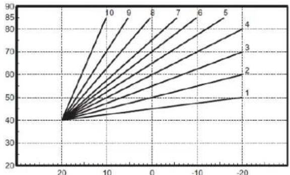
line
| x | y | |----|------| | 20 | 40 | | 10 | 85 | | 0 | 80 | | -10| 75 | | -20| 70 |FERROLI Poland Sp. z o.o.
ul. Narutowicza 53
41-200 Sosnowiec
www.ferroli.com.pl

- CE
- AVVERTENZE GENERALI
- EN
- GENERAL WARNINGS
- OPERATING INSTRUCTIONS
- Introduction
- Control panel
- Panel - legend
- Indication during operation
- Heating
- DHW (Comfort)
- Exclude hot water storage tank (economy)
- Lighting and turning off
- Boiler lighting
- Turning the boiler off
- Adjustments
- Summer/Winter Switchover
- Heating temperature setting
- DHW temperature adjustment
- Room temperature adjustment (with optional room thermostat)
- Room temperature adjustment (with optional remote timer control)
- Sliding temperature
- Compensation curve and curve offset
- Adjustments from Remote Timer Control
- Water system pressure adjustment
- INSTALLATION
- General Instructions
- Place of installation
- Plumbing connections
- Water system characteristics
- Antifreeze system, antifreeze fluids, additives and inhibitors
- Connection to a storage tank for domestic hot water production
- Burner connection
- Electrical connections
- Connection to the electrical grid
- Room thermostat (optional)
- Accessing the electrical terminal block
- Connection to the flue
- SERVICE AND MAINTENANCE
- Adjustments
- TEST mode activation
- Burner adjustment
- Start-up
- Before lighting the boiler
- Checks during operation
- Maintenance
- Periodical check
- Boiler cleaning
- Troubleshooting
- Diagnostics
- TECHNICAL DATA AND CHARACTERISTICS
- Dimensions, connections and main components
- System delivery 1" 1/2"
- A mbar
- ErP product fiche
- Wiring diagram
- ALGEMENE WAARSCHUWINGEN
- ALGEMENE WAARSCHUWINGEN
- Sanitair water (Comfort)
- Uitschakeling boiler (economy)
Brand : FERROLI
Model : Atlas D
Category : Central heating boiler