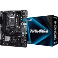
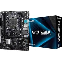
H310MSTX - Motherboard ASROCK - Free user manual and instructions
Find the device manual for free H310MSTX ASROCK in PDF.
Download the instructions for your Motherboard in PDF format for free! Find your manual H310MSTX - ASROCK and take your electronic device back in hand. On this page are published all the documents necessary for the use of your device. H310MSTX by ASROCK.
USER MANUAL H310MSTX ASROCK
Version 1.0 Published April 2018 is device complies with Part 15 of the FCC Rules. Operation is subject to the following two conditions: (1) this device may not cause harmful interference, and (2) this device must accept any interference received, including interference that may cause undesired operation.
CALIFORNIA, USA ONLY
e Lithium battery adopted on this motherboard contains Perchlorate, a toxic substance controlled in Perchlorate Best Management Practices (BMP) regulations passed by the California Legislature. When you discard the Lithium battery in California, USA, please follow the related regulations in advance. “Perchlorate Material-special handling may apply, see www.dtsc.ca.gov/hazardouswaste/ perchlorate”AUSTRALIA ONLY Our goods come with guarantees that cannot be excluded under the Australian Consumer Law. You are entitled to a replacement or refund for a major failure and compensation for any other reasonably foreseeable loss or damage caused by our goods. You are also entitled to have the goods repaired or replaced if the goods fail to be of acceptable quality and the failure does not amount to a major failure. e terms HDMI™ and HDMI High-Denition Multimedia Interface, and the HDMI logo are trademarks or registered trademarks of HDMI Licensing LLC in the United States and other countries.1 English
H310M-STX / H310M-STX/COM
Back Side View3 English
H310M-STX / H310M-STX/COM
H310M-STX / H310M-STX/COM
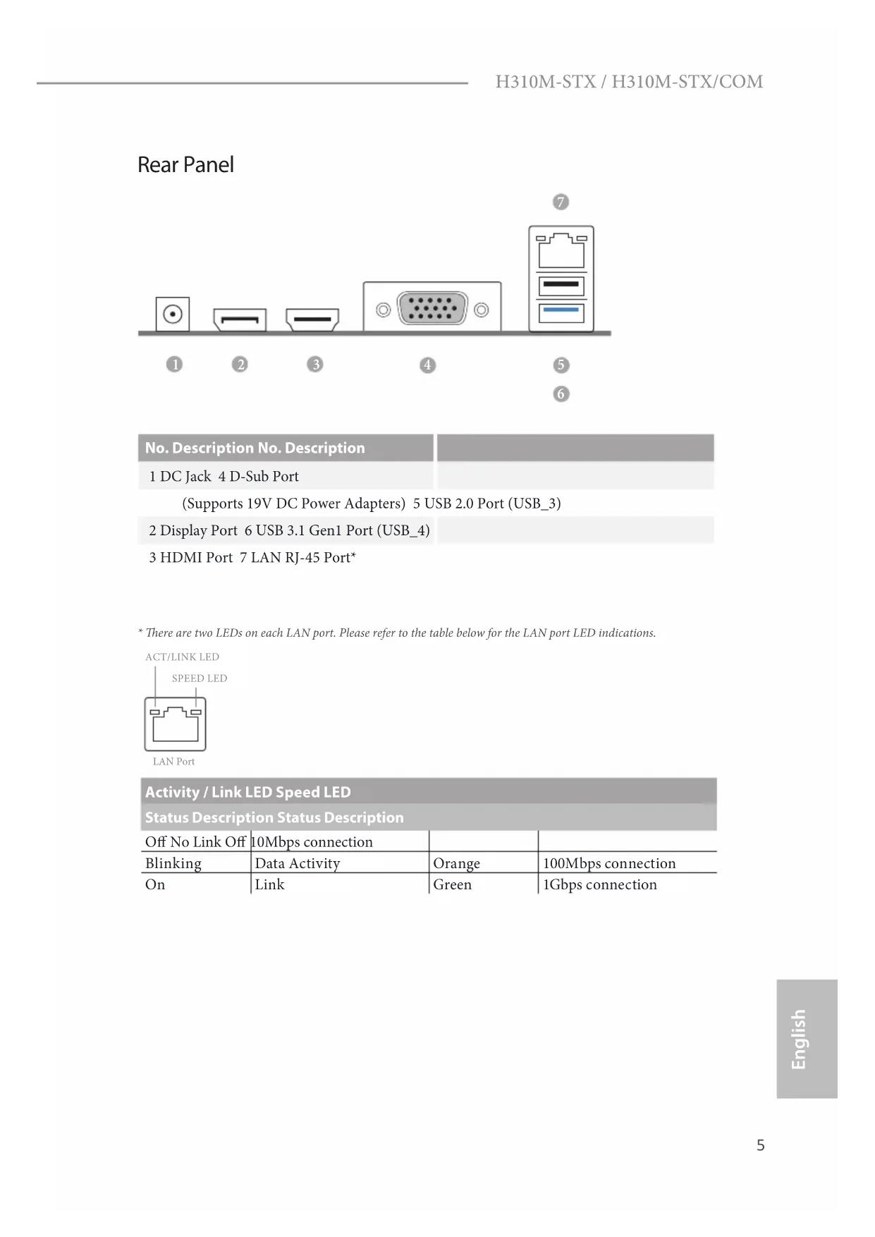
Rear Panel No. Description No. Description 1 DC Jack 4 D-Sub Port (Supports 19V DC Power Adapters) 5 USB 2.0 Port (USB_3) 2 Display Port 6 USB 3.1 Gen1 Port (USB_4) 3 HDMI Port 7 LAN RJ-45 Port*
- ere are two LEDs on each LAN port. Please refer to the table below for the LAN port LED indications. Activity / Link LED Speed LED Status Description Status Description O No Link O 10Mbps connection Blinking Data Activity Orange 100Mbps connection On Link Green 1Gbps connection ACT/LINK LEDSPEED LEDLAN Port
ank you for purchasing H310M-STX / H310M-STX/COM motherboard. In this documentation, Chapter 1 and 2 contains the introduction of the motherboard and step-by-step installation guides. Chapter 3 contains the operation guide of the soware and utilities. Chapter 4 contains the conguration guide of the BIOS setup.
H310M-STX / H310M-STX/COM Motherboard (Mini-STX Form Factor)
H310M-STX / H310M-STX/COM Support CD
1 x I/O Panel Shield
2 x Serial ATA(SATA) Data with Power Cable (Optional)
1 x Screw for WiFi Module (M2*2) (Optional) Because the motherboard specications and the BIOS soware might be updated, the content of this documentation will be subject to change without notice.7 English
H310M-STX / H310M-STX/COM
Mini-STX Form Factor CPU
Supports CPU up to 65W
5 Power Phase design
Supports Intel® Turbo Boost 2.0 Technology Chipset
Dual Channel DDR4 Memory Technology
Supports DDR4 2666/2400/2133 non-ECC, un-buered memory
Supports Intel® Extreme Memory Prole (XMP) 2.0
Intel® UHD Graphics Built-in Visuals and the VGA outputs can be supported only with processors which are GPU integrated.
Supports Intel® UHD Graphics Built-in Visuals : Intel® Quick Sync Video with AVC, MVC (S3D) and MPEG-2 Full HW Encode1,
HWAEncode/Decode: AVC/H.264, HEVC/H.265 8-bit, HEVC/H.265 10-bit, VP8, VP9 8-bit, VP9 10-bit (Decode only), MPEG2, MJPEG, VC-1 (Decode only)8 English
Max. shared memory 1024MB
- e size of maximum shared memory may vary from dierent operating systems.
- Supports up to 2 displays simultaneously
Supports HDMI with max. resolution up to 4K x 2K (4096x2160) @ 30Hz
Supports D-Sub with max. resolution up to 1920x1200 @ 60Hz
Supports DisplayPort 1.2 with max. resolution up to 4K x 2K (4096x2304) @ 60Hz
Supports Auto Lip Sync, Deep Color (12bpc), xvYCC and HBR (High Bit Rate Audio) with HDMI Port (Compliant HDMI monitor is required)
Supports HDCP with HDMI and DisplayPort 1.2 Ports
Supports 4K Ultra HD (UHD) playback with HDMI and DisplayPort 1.2 Ports Audio
1 x Headphone/Headset Jack
Supports Wake-On-LAN
Supports Lightning/ESD Protection
Supports Energy Ecient Ethernet 802.3az
Supports PXE Front Panel I/O
1 x Headphone/Headset Jack
1 x USB 3.1 Gen1 Type-A Port (Supports ESD Protection)
H310M-STX / H310M-STX/COM
1 x DC Jack (Compatible with the 19V power adapter)*
- Please use 120W power adapter for 65W CPU and 90W power adapter for 35W CPU.
1 x USB 2.0 Port (Supports ESD Protection)
1 x USB 3.1 Gen1 Port (Supports ESD Protection)
1 x RJ-45 LAN Port with LED (ACT/LINK LED and SPEED LED) Storage
2 x SATA3 6.0 Gb/s with Power Connectors, support NCQ, AHCI and Hot Plug
- Supports NVMe SSD as boot disks Connector
1 x COM Port Header (for H310M-STX/COM only)
2 x CPU Fan Connectors (2 x 4-pin)
1 x USB 2.0 Header (Supports 2 USB 2.0 ports) (Supports ESD Protection)
AMI UEFI Legal BIOS with multilingual GUI support
ACPI 6.0 Compliant wake up events
DRAM Voltage Multi-adjustment Hardware Monitor
CPU temperature sensing
CPU Quiet Fan (Auto adjust chassis fan speed by CPU temperature)
CPU Fan multi-speed control
ErP/EuP ready (ErP/EuP ready power supply is required) Mini-STX Chassis Support List Please realize that there is a certain risk involved with overclocking, including adjusting the setting in the BIOS, applying Untied Overclocking Technology, or using third-party overclocking tools. Overclocking may aect your system’s stability, or even cause damage to the components and devices of your system. It should be done at your own risk and expense. We are not responsible for possible damage caused by overclocking. Vendor Model SilverStone Technology Inc. VT01S AKasa A-STX04-A1B / A-STX04-M1B11 English
H310M-STX / H310M-STX/COM
is is a Mini-STX form factor motherboard. Before you install the motherboard, study the conguration of your chassis to ensure that the motherboard ts into it. Pre-installation Precautions Take note of the following precautions before you install motherboard components or change any motherboard settings.
Make sure to unplug the power cord before installing or removing the motherboard components. Failure to do so may cause physical injuries and damages to motherboard components.
In order to avoid damage from static electricity to the motherboard’s components, NEVER place your motherboard directly on a carpet. Also remember to use a grounded wrist strap or touch a safety grounded object before you handle the components.
Hold components by the edges and do not touch the ICs.
Whenever you uninstall any components, place them on a grounded anti-static pad or in the bag that comes with the components.
When placing screws to secure the motherboard to the chassis, please do not over- tighten the screws! Doing so may damage the motherboard.
Chapter 2 Installation12
2.1 Installing the CPU
1. Before you insert the 1151-Pin CPU into the socket, please check if the PnP cap is on the
socket, if the CPU surface is unclean, or if there are any bent pins in the socket. Do not force to insert the CPU into the socket if above situation is found. Otherwise, the CPU will be seriously damaged.
H310M-STX / H310M-STX/COM
English Please save and replace the cover if the processor is removed. e cover must be placed if you wish to return the motherboard for aer service.15 English
H310M-STX / H310M-STX/COM
2.2 Installing the CPU Fan and Heatsink
is motherboard provides two 260-pin DDR4 (Double Data Rate 4) SO-DIMM slots. e SO-DIMM only ts in one correct orientation. It will cause permanent damage to the motherboard and the SO-DIMM if you force the SO-DIMM into the slot at incorrect orientation. It is not allowed to install a DDR, DDR2 or DDR3 memory module into a DDR4 slot; otherwise, this motherboard and SO-DIMM may be damaged.17 English
H310M-STX / H310M-STX/COM
2.4 Onboard Headers and Connectors
System Panel Header (9-pin PANEL1) (see p.1, No. 7) Connect the power button, reset button and system status indicator on the chassis to this header according to the pin assignments below. Note the positive and negative pins before connecting the cables. GND
RESET#PWRBTN#PLED-PLED+
GND Onboard headers and connectors are NOT jumpers. Do NOT place jumper caps over these headers and connectors. Placing jumper caps over the headers and connectors will cause permanent damage to the motherboard. PWRBTN (Power Button): Connect to the power button on the chassis front panel. You may congure the way to turn o your system using the power button. RESET (Reset Button): Connect to the reset button on the chassis front panel. Press the reset button to restart the computer if the computer freezes and fails to perform a normal restart. PLED (System Power LED): Connect to the power status indicator on the chassis front panel. e LED is on when the system is operating. e LED keeps blinking when the system is in S1/S3 sleep state. e LED is o when the system is in S4 sleep state or powered o (S5). HDLED (Hard Drive Activity LED): Connect to the hard drive activity LED on the chassis front panel. e LED is on when the hard drive is reading or writing data. e front panel design may dier by chassis. A front panel module mainly consists of power button, reset button, power LED, hard drive activity LED, speaker and etc. When connect- ing your chassis front panel module to this header, make sure the wire assignments and the pin assignments are matched correctly.19 English
H310M-STX / H310M-STX/COM
MONO Speaker Header (4-pin SPEAKER1) (see p.1, No. 4) Please connect the chassis speaker to this header. Serial ATA3 Connectors (see p.2, No. 10 and 11) ese two SATA3 connectors support SATA data cables for internal storage devices with up to
6.0 Gb/s data transfer rate.
*e SATA3 connectors support 2.5-inch hard drive (+5V) and do not support 3.5-inch hard drive (+12V) USB 2.0 Header (9-pin USB_5_6) (see p.1, No. 5) ere is one header on this motherboard. is USB 2.0 header can support two ports. CPU Fan Connectors (4-pin CPU_FAN1) (see p.1, No. 3) (4-pin CPU_FAN2) (see p.1, No. 1) is motherboard provides two 4-Pin CPU fan (Quiet Fan) connectors. If you plan to connect a 3-Pin CPU fan, please connect it to Pin 1-3. DUMMYGNDGND
Front_L+ Front_R- Front_R+ Front_L-
PIN Signal Name PIN Signal Name
English Serial Port Header (for H310M-STX/COM only) (9-pin COM1) (see p.1, No. 6) is COM1 header supports a serial port module. Chassis Intrusion Header (2-pin CI1) (see p.1, No. 9) is motherboard supports CASE OPEN detection feature that detects if the chassis cove has been removed. is feature requires a chassis with chassis intrusion detection design. Clear CMOS Pad (see p.2, No. 12) Clear CMOS Pad allows you to clear the data in CMOS. To clear CMOS, disconnect the power supply and short the Clear CMOS Pad. Audio Header (5-pin AUDIO3) (see p.1, No. 8) is Audio header allows you to connect the audio cable for head- phone.
H310M-STX / H310M-STX/COM
2.5 M.2 WiFi/BT Module and Intel® CNVi (Integrated WiFi/BT)
Installation Guide e M.2, also known as the Next Generation Form Factor (NGFF), is a small size and versatile card edge connector that aims to replace mPCIe and mSATA. e M.2 Socket (Key E) supports type 2230 WiFi/BT module and Intel® CNVi (Integrated WiFi/BT).
- e M.2 socket does not support SATA M.2 SSDs. Installing the WiFi/BT module or Intel® CNVi (Integrated WiFi/BT) Step 1 Prepare a type 2230 WiFi/BT module or Intel® CNVi (Integrated WiFi/BT) and the screw. PCB Length: 3cm Module Type: Type2230
Step 2 Find the nut location to be used. Before you install Intel® Integrated Connectivity (CNVi) module, be sure to turn o the AC power.22 English
Step 3 Gently insert the WiFi/BT module or Intel® CNVi (Integrated WiFi/ BT) into the M.2 slot. Please be aware that the module only ts in one orientation. Step 4 Tighten the screw with a screwdriver to secure the module into place. Please do not overtighten the screw as this might damage the module.23 English
H310M-STX / H310M-STX/COM
2.6 M.2_SSD (NGFF) Module Installation Guide
e M.2, also known as the Next Generation Form Factor (NGFF), is a small size and versatile card edge connector that aims to replace mPCIe and mSATA. The Ultra M.2 Socket supports type 2280 M.2 SATA3 6.0 Gb/s module and M.2 PCI Express module up to Gen3 x4 (32 Gb/s). Installing the M.2_SSD (NGFF) Module Step 1 Prepare a M.2_SSD (NGFF) module and the screw. Step 2 Gently insert the M.2 (NGFF) SSD module into the M.2 slot. Please be aware that the M.2 (NGFF) SSD module only ts in one orientation. Step 3 Tighten the screw with a screwdriver to secure the module into place. Please do not overtighten the screw as this might damage the module.
H310M-STX / H310M-STX/COM
2.7 SD Card Installation Guide
1. Locate the SD Card Slot on the back side of the motherboard
2. Carefully insert the SD Card into the slot until it clicks.26
H310M-STX / H310M-STX/COM
H310M-STX / H310M-STX/COM
H310M-STX / H310M-STX/COM
RESET#PWRBTN#PLED-PLED+
Front_L+ Front_R- Front_R+ Front_L-
H310M-STX / H310M-STX/COM
H310M-STX / H310M-STX/COM
H310M-STX / H310M-STX/COM
H310M-STX / H310M-STX/COM
RESET#PWRBTN#PLED-PLED+
Front_L+ Front_R- Front_R+ Front_L-
H310M-STX / H310M-STX/COM
Scheda madre H310M-STX / H310M-STX/COM (Form Factor Mini-STX)
H310M-STX / H310M-STX/COM
Form Factor Mini-STX CPU
Supporto WOL (Wake-On-LAN)
Supporto Energy Ecient Ethernet 802.3az
H310M-STX / H310M-STX/COM
H310M-STX / H310M-STX/COM
RESET#PWRBTN#PLED-PLED+
Front_L+ Front_R- Front_R+ Front_L-
H310M-STX / H310M-STX/COM
H310M-STX / H310M-STX/COM
H310M-STX / H310M-STX/COM
H310M-STX / H310M-STX/COM
RESET#PWRBTN#PLED-PLED+
Front_L+Front_R- Front_R+ Front_L-
H310M-STX / H310M-STX/COM
H310M-STX / H310M-STX/COM
H310M-STX / H310M-STX/COM
H310M-STX / H310M-STX/COM
RESET#PWRBTN#PLED-PLED+
Front_L+Front_R- Front_R+ Front_L-
H310M-STX / H310M-STX/COM
H310M-STX / H310M-STX/COM
H310M-STX / H310M-STX/COM
H310M-STX / H310M-STX/COM
RESET#PWRBTN#PLED-PLED+
Front_L+ Front_R- Front_R+ Front_L-
H310M-STX / H310M-STX/COM
H310M-STX / H310M-STX/COM
H310M-STX / H310M-STX/COM
H310M-STX / H310M-STX/COM
RESET#PWRBTN#PLED-PLED+
Front_L+ Front_R- Front_R+ Front_L-
H310M-STX / H310M-STX/COM
H310M-STX / H310M-STX/COM
H310M-STX / H310M-STX/COM
H310M-STX / H310M-STX/COM
RESET#PWRBTN#PLED-PLED+
Front_L+ Front_R- Front_R+ Front_L-
H310M-STX / H310M-STX/COM
H310M-STX / H310M-STX/COM
H310M-STX / H310M-STX/COM
H310M-STX / H310M-STX/COM
RESET#PWRBTN#PLED-PLED+
Front_L+ Front_R- Front_R+ Front_L-
H310M-STX / H310M-STX/COM
H310M-STX / H310M-STX/COM
H310M-STX / H310M-STX/COM
H310M-STX / H310M-STX/COM
RESET#PWRBTN#PLED-PLED+
Front_L+ Front_R- Front_R+ Front_L-
H310M-STX / H310M-STX/COM
H310M-STX / H310M-STX/COM
H310M-STX / H310M-STX/COM
H310M-STX / H310M-STX/COM
RESET#PWRBTN#PLED-PLED+
H310M-STX / H310M-STX/COM
Front_L+ Front_R- Front_R+ Front_L-
H310M-STX / H310M-STX/COM
1 x Soket Headphone/Headset
1 x Soket Headphone/Headset
H310M-STX / H310M-STX/COM
Responsible Party Name: ASRock Incorporation Address:13848 Magnolia Ave, Chino, CA91710+1-909-590-8308/+1-909-590-1026 Phone/FaxNo: hereby declares that the product Product Name : Motherboard Model Number : Conforms to the following specifications:
FCC Part 15, Subpart B, Unintentional Radiators
Supplementary Information: is device complies with part 15 of the FCC Rules. Operation is subject to the following two conditions: (1) is device may not cause harmful interference, and (2) this device must accept any interference received, including interference that may cause undesired operation. Representative Person’s Name: James Signature : Date : May 12, 2017
H310M-STX / H310M-STX/COMEMC
LVD —Directive 2014/35/EU (from April 20th, 2016) EN 60950-1 : 2011+ A2: 2013 ☐
(EU conformity marking)
EU Declaration of Conformity
For the following equipment:Motherboard(Product Name)H310M-STX / H310M-STX/COM (Model Designation / Trade Name)P/N: 15G067024000AK V1.0