Z170M OC Formula - Motherboard ASROCK - Free user manual and instructions
Find the device manual for free Z170M OC Formula ASROCK in PDF.
Download the instructions for your Motherboard in PDF format for free! Find your manual Z170M OC Formula - ASROCK and take your electronic device back in hand. On this page are published all the documents necessary for the use of your device. Z170M OC Formula by ASROCK.
USER MANUAL Z170M OC Formula ASROCK
Version 1.0 Published January 2016 Copyright©2016 ASRock INC. All rights reserved. Copyright Notice: No part of this documentation may be reproduced, transcribed, transmitted, or translated in any language, in any form or by any means, except duplication of documentation by the purchaser for backup purpose, without written consent of ASRock Inc. Products and corporate names appearing in this documentation may or may not be registered trademarks or copyrights of their respective companies, and are used only for identication or explanation and to the owners’ benet, without intent to infringe. Disclaimer: Specications and information contained in this documentation are furnished for informational use only and subject to change without notice, and should not be constructed as a commitment by ASRock. ASRock assumes no responsibility for any errors or omissions that may appear in this documentation. With respect to the contents of this documentation, ASRock does not provide warranty of any kind, either expressed or implied, including but not limited to the implied warranties or conditions of merchantability or tness for a particular purpose. In no event shall ASRock, its directors, ocers, employees, or agents be liable for any indirect, special, incidental, or consequential damages (including damages for loss of prots, loss of business, loss of data, interruption of business and the like), even if ASRock has been advised of the possibility of such damages arising from any defect or error in the documentation or product. is device complies with Part 15 of the FCC Rules. Operation is subject to the following two conditions: (1) this device may not cause harmful interference, and (2) this device must accept any interference received, including interference that may cause undesired operation.
CALIFORNIA, USA ONLY
e Lithium battery adopted on this motherboard contains Perchlorate, a toxic substance controlled in Perchlorate Best Management Practices (BMP) regulations passed by the California Legislature. When you discard the Lithium battery in California, USA, please follow the related regulations in advance. “Perchlorate Material-special handling may apply, see www.dtsc.ca.gov/hazardouswaste/ perchlorate” ASRock Website: http://www.asrock.comAUSTRALIA ONLY Our goods come with guarantees that cannot be excluded under the Australian Consumer Law. You are entitled to a replacement or refund for a major failure and compensation for any other reasonably foreseeable loss or damage caused by our goods. You are also entitled to have the goods repaired or replaced if the goods fail to be of acceptable quality and the failure does not amount to a major failure. If you require assistance please call ASRock Tel : +886-2-28965588 ext.123 (Standard International call charges apply) e terms HDMI™ and HDMI High-Denition Multimedia Interface, and the HDMI logo are trademarks or registered trademarks of HDMI Licensing LLC in the United States and other countries. Manufactured under license under U.S. Patent Nos: 5,956,674; 5,974,380; 6,487,535; 7,003,467 & other U.S. and worldwide patents issued & pending. DTS, the Symbol, & DTS and the Symbol together is a registered trademark & DTS Connect, DTS Interactive, DTS Neo:PC are trademarks of DTS, Inc. Product includes soware. © DTS, Inc., All Rights Reserved.1 English Z170M OC Formula Motherboard Layout Intel Z170 ATX 12V1 SPK_PLED1CPU_FAN1CPU_FAN2CHA_FAN3CHA_FAN1CHA_FAN2PuritySound 3
English Z170M OC Formula
- ere are two LEDs on each LAN port. Please refer to the table below for the LAN port LED indications. Activity / Link LED Speed LED Status Description Status Description O No Link O 10Mbps connection Blinking Data Activity Orange 100Mbps connection On Link Green 1Gbps connection ** If you use a 2-channel speaker, please connect the speaker’s plug into “Front Speaker Jack”. See the table below for connection details in accordance with the type of speaker you use. Audio Output Channels Front Speaker (No. 6) Rear Speaker (No. 4) Central / Bass (No. 3) Line In (No. 5) 2 V -- -- -- 4 V V -- -- 6 V V V -- 8 V V V V To enable Multi-Streaming, you need to connect a front panel audio cable to the front panel audio header. Aer restarting your computer, you will nd the “Mixer” tool on your system. Please select “Mixer ToolBox” , click “Enable playback multi-streaming”, and click “ok”. Choose “2CH”, “4CH”, “6CH”, or “8CH” and then you are allowed to select “Realtek HDA Primary output” to use the Rear Speaker, Central/Bass, and Front Speaker, or select “Realtek HDA Audio 2nd output” to use the front panel audio.
ank you for purchasing ASRock Z170M OC Formula motherboard, a reliable motherboard produced under ASRock’s consistently stringent quality control. It delivers excellent performance with robust design conforming to ASRock’s commitment to quality and endurance.
1 x I/O Panel Shield
1 x Screw for M.2 Socket Because the motherboard specications and the BIOS soware might be updated, the content of this documentation will be subject to change without notice. In case any modi-cations of this documentation occur, the updated version will be available on ASRock’s website without further notice. If you require technical support related to this mother-board, please visit our website for specic information about the model you are using. You may nd the latest VGA cards and CPU support list on ASRock’s website as well. ASRock website http://www.asrock.com.7 English Z170M OC Formula
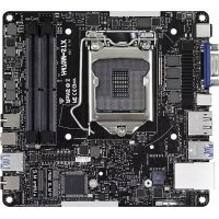
Micro ATX Form Factor CPU
14 Power Phase design
Supports Intel® Turbo Boost 2.0 Technology
Supports Intel® K-Series unlocked CPUs
Supports ASRock BCLK Full-range Overclocking
Supports ASRock Hyper BCLK Engine Chipset
Dual Channel DDR4 Memory Technology
Supports ECC UDIMM memory modules (operate in non- ECC mode)
- 4500+(OC) memory frequency can only be achieved when a single memory module is installed (Single channel memory).
- Please refer to Memory Support List on ASRock's website for more information. (http://www.asrock.com/)
Max. capacity of system memory: 32GB
Supports Intel® Extreme Memory Prole (XMP) 2.0
- Supports NVMe SSD as boot disks
Intel® HD Graphics Built-in Visuals and the VGA outputs can be supported only with processors which are GPU integrated.
Supports Intel® HD Graphics Built-in Visuals : Intel® Quick Sync Video with AVC, MVC (S3D) and MPEG-2 Full HW Encode1, Intel® InTru
Dual graphics output: Support HDMI and DisplayPort 1.2 ports by independent display controllers
Supports HDMI with max. resolution up to 4K x 2K (4096x2304) @ 24Hz
Supports Auto Lip Sync, Deep Color (12bpc), xvYCC and HBR (High Bit Rate Audio) with HDMI Port (Compliant HDMI monitor is required)
Supports Accelerated Media Codecs: HEVC, VP8, VP9
Supports HDCP with DVI-D, HDMI and DisplayPort 1.2 Ports
Supports Full HD 1080p Blu-ray (BD) playback with HDMI and DisplayPort 1.2 Ports Audio
7.1 CH HD Audio with Content Protection (Realtek
Supports Surge Protection (ASRock Full Spike Protection)
Supports Purity Sound
- Nichicon Fine Gold Series Audio Caps - 115dB SNR DAC with Dierential Amplier - TI® NE5532 Premium Headset Amplier (Supports up to 600 Ohms headsets) - Pure Power-In - Direct Drive Technology - PCB Isolate Shielding
Supports DTS Connect9 English Z170M OC Formula LAN
Supports Wake-On-LAN
Supports Lightning/ESD Protection (ASRock Full Spike Protection)
Supports Energy Ecient Ethernet 802.3az
Supports PXE Rear Panel I/O
2 x USB 2.0 Ports (Supports ESD Protection (ASRock Full Spike Protection))
4 x USB 3.0 Ports (Intel® Z170) (Supports ESD Protection (ASRock Full Spike Protection))
1 x RJ-45 LAN Port with LED (ACT/LINK LED and SPEED LED)
HD Audio Jacks: Rear Speaker / Central / Bass / Line in / Front Speaker / Microphone Storage
6 x SATA3 6.0 Gb/s Connectors by Intel® Z170, support RAID (RAID 0, RAID 1, RAID 5, RAID 10, Intel Rapid Storage Technology 14 and Intel Smart Response Technology), NCQ, AHCI and Hot Plug
2 x SATA3 6.0 Gb/s Connectors by ASMedia ASM1061, sup- port NCQ, AHCI and Hot Plug
- Support to be announced
- M2_1, SATA3_0, SATA3_1 and SATA_EXP0 share lanes. If either one of them is in use, the others will be disabled.
1 x Ultra M.2 Socket, supports type 2230/2242/2260/2280/22110 M.2 SATA3 6.0 Gb/s module and M.2 PCI Express module up to Gen3 x4 (32 Gb/s)** ** Supports NVMe SSD as boot disks ** Supports ASRock U.2 Kit10 English Connector
1 x Power LED and Speaker Header
2 x CPU Fan Connectors (1 x 3-pin, 1 x 4-pin) (Smart Fan Speed Control)
- CPU_FAN1, CHA_FAN_1, CHA_FAN_2 and CHA_FAN_3 can auto detect if 3-pin or 4-pin fan is in use.
- e CPU Fan Connector supports the CPU fan of maximum 1A (12W) fan power.
1 x 8 pin 12V Power Connector (Hi-Density Power Connec- tor)
1 x Front Panel Audio Connector
- Only one underbolt AIC Card is supported.
2 x USB 2.0 Headers (Support 4 USB 2.0 ports) (Supports ESD Protection (ASRock Full Spike Protection))
1 x USB 3.0 Header (Supports 2 USB 3.0 ports) (Supports ESD Protection (ASRock Full Spike Protection))
1 x Dr. Debug with LED
1 x Power Switch with LED
1 x Reset Switch with LED
: 1 x 7-set of onboard voltage measurement points laid
Rapid OC Buttons: +/- buttons to adjust OC frequency
2 x 128Mb AMI UEFI Legal BIOS with multilingual GUI support (1 x Main BIOS and 1 x Backup BIOS)
Supports Secure Backup UEFI Technology
ACPI 5.0 Compliant wake up events
CPU, GT_CPU, DRAM, VPPM, PCH 1.0V, VCCIO, VCCPLL, VCCSA Voltage Multi-adjustment11 English Z170M OC Formula Hardware Monitor
CPU/Chassis temperature sensing
CPU/Chassis Quiet Fan (Auto adjust chassis fan speed by CPU temperature)
CPU/Chassis Fan multi-speed control
- To install Windows® 7 OS, a modied installation disk with xHCI drivers packed into the ISO le is required. Please refer to page 204 for more detailed instructions.
ErP/EuP Ready (ErP/EuP ready power supply is required) Please realize that there is a certain risk involved with overclocking, including adjusting the setting in the BIOS, applying Untied Overclocking Technology, or using third-party overclocking tools. Overclocking may aect your system’s stability, or even cause damage to the components and devices of your system. It should be done at your own risk and expense. We are not responsible for possible damage caused by overclocking.
- For detailed product information, please visit our website: http://www.asrock.com12 English is is a Micro ATX form factor motherboard. Before you install the motherboard, study the conguration of your chassis to ensure that the motherboard ts into it. Pre-installation Precautions Take note of the following precautions before you install motherboard components or change any motherboard settings.
Make sure to unplug the power cord before installing or removing the motherboard components. Failure to do so may cause physical injuries and damages to motherboard components.
In order to avoid damage from static electricity to the motherboard’s components, NEVER place your motherboard directly on a carpet. Also remember to use a grounded wrist strap or touch a safety grounded object before you handle the components.
Hold components by the edges and do not touch the ICs.
Whenever you uninstall any components, place them on a grounded anti-static pad or in the bag that comes with the components.
When placing screws to secure the motherboard to the chassis, please do not over- tighten the screws! Doing so may damage the motherboard.
Chapter 2 Installation13
English Z170M OC Formula
2.1 Installing the CPU
1. Before you insert the 1151-Pin CPU into the socket, please check if the PnP cap is on the
socket, if the CPU surface is unclean, or if there are any bent pins in the socket. Do not force to insert the CPU into the socket if above situation is found. Otherwise, the CPU will be seriously damaged.
Please save and replace the cover if the processor is removed. e cover must be placed if you wish to return the motherboard for aer service.15 English Z170M OC Formula
2.2 Installing the CPU Fan and Heatsink
is motherboard provides two 288-pin DDR4 (Double Data Rate 4) DIMM slots. e DIMM only ts in one correct orientation. It will cause permanent damage to the motherboard and the DIMM if you force the DIMM into the slot at incorrect orientation. It is not allowed to install a DDR, DDR2 or DDR3 memory module into a DDR4 slot; other- wise, this motherboard and DIMM may be damaged.17 English Z170M OC Formula
ere are 3 PCI Express slots on the motherboard. PCIe slots: PCIE1 (PCIe 3.0 x16 slot) is used for PCI Express x16 lane width graphics cards. PCIE2 (PCIe 3.0 x16 slot) is used for PCI Express x8 lane width graphics cards. PCIE3 (PCIe 3.0 x16 slot) is used for PCI Express x4 lane width graphics cards. PCIe Slot Congurations Before installing an expansion card, please make sure that the power supply is switched o or the power cord is unplugged. Please read the documentation of the expansion card and make necessary hardware settings for the card before you start the installation. For a better thermal environment, please connect a chassis fan to the motherboard’s chassis fan connector (CHA_FAN1, CHA_FAN2 or CHA_FAN3) when using multiple graphics cards.
Single Graphics Card x16 N/A N/A Two Graphics Cards in CrossFireX
Mode x8 x8 N/A19 English Z170M OC Formula
e illustration shows how jumpers are setup. When the jumper cap is placed on the pins, the jumper is “Short”. If no jumper cap is placed on the pins, the jumper is “Open”. e illustration shows a 3-pin jumper whose pin1 and pin2 are “Short” when a jumper cap is placed on these 2 pins. Clear CMOS Jumper (CLRCMOS1) (see p.1, No. 40) CLRCMOS1 allows you to clear the data in CMOS. To clear and reset the system parameters to default setup, please turn o the computer and unplug the power cord from the power supply. Aer waiting for 15 seconds, use a jumper cap to short pin2 and pin3 on CLRCMOS1 for 5 seconds. However, please do not clear the CMOS right aer you update the BIOS. If you need to clear the CMOS when you just nish updating the BIOS, you must boot up the system rst, and then shut it down before you do the clear-CMOS action. Please be noted that the password, date, time, and user default prole will be cleared only if the CMOS battery is removed. Clear CMOSDefault e Clear CMOS Switch has the same function as the Clear CMOS jumper.20 English
2.6 Onboard Headers and Connectors
System Panel Header (9-pin PANEL1) (see p.1, No. 28) Connect the power switch, reset switch and system status indicator on the chassis to this header according to the pin assignments below. Note the positive and negative pins before connecting the cables. Power LED and Speaker Header (7-pin SPK_PLED1) (see p.1, No. 34) Please connect the chassis power LED and the chassis speaker to this header. GND
RESET#PWRBTN#PLED-PLED+
GND PWRBTN (Power Switch): Connect to the power switch on the chassis front panel. You may congure the way to turn o your system using the power switch. RESET (Reset Switch): Connect to the reset switch on the chassis front panel. Press the reset switch to restart the computer if the computer freezes and fails to perform a normal restart. PLED (System Power LED): Connect to the power status indicator on the chassis front panel. e LED is on when the system is operating. e LED keeps blinking when the system is in S1/S3 sleep state. e LED is o when the system is in S4 sleep state or powered o (S5). HDLED (Hard Drive Activity LED): Connect to the hard drive activity LED on the chassis front panel. e LED is on when the hard drive is reading or writing data. e front panel design may dier by chassis. A front panel module mainly consists of power switch, reset switch, power LED, hard drive activity LED, speaker and etc. When connect- ing your chassis front panel module to this header, make sure the wire assignments and the pin assignments are matched correctly. Onboard headers and connectors are NOT jumpers. Do NOT place jumper caps over these headers and connectors. Placing jumper caps over the headers and connectors will cause permanent damage to the motherboard.
English Z170M OC Formula Serial ATA3 Connectors (SATA3_0 see p.1, No. 20) (SATA3_1: see p.1, No. 22) (SATA3_2: see p.1, No. 21) (SATA3_3: see p.1, No. 23) (SATA3_4: see p.1, No. 27) (SATA3_5: see p.1, No. 26) (SATA3_A1 see p.1, No. 18) (SATA3_A2 see p.1, No. 17) ese eight SATA3 connectors support SATA data cables for internal storage devices with up to 6.0 Gb/s data transfer rate. e SATA3_0, SATA3_1 are shared with the SATA_EXP0. e SATA3_2, SATA3_3 are shared with the SATA_ EXP1. To minimize the boot time, use Intel® Z170 SATA ports (SATA3_0) for your bootable devices. Serial ATA Express Connectors (SATA_EXP_0: see p.1, No. 24) (SATA_EXP_1: see p.1, No. 25) Please connect either SATA or PCIe storage devices to these connectors. *e upper SATA Express Connector (SATA_ EXP0) is shared with the SATA3_0, SATA3_1 and the Ultra M.2 Socket (M2 _1). USB 2.0 Headers (9-pin USB3_4) (see p.1, No. 33) (9-pin USB5_6) (see p.1, No. 32) Besides two USB 2.0 ports on the I/O panel, there are two headers on this motherboard. Each USB
2.0 header can support
English USB 3.0 Header (19-pin USB3_5_6) (see p.1, No. 11) Besides four USB 3.0 ports on the I/O panel, there is one header on this motherboard. Each USB
3.0 header can support
two ports. Front Panel Audio Header (9-pin HD_AUDIO1) (see p.1, No. 37) is header is for connecting audio devices to the front audio panel. Chassis Fan Connectors (4-pin CHA_FAN1) (see p.1, No. 19) (4-pin CHA_FAN2) (see p.1, No. 30) (4-pin CHA_FAN3) (see p.1, No. 39) Please connect fan cables to the fan connectors and match the black wire to the ground pin.
1. High Denition Audio supports Jack Sensing, but the panel wire on the chassis must sup-
port HDA to function correctly. Please follow the instructions in our manual and chassis manual to install your system.
2. If you use an AC’97 audio panel, please install it to the front panel audio header by the
steps below: A. Connect Mic_IN (MIC) to MIC2_L. B. Connect Audio_R (RIN) to OUT2_R and Audio_L (LIN) to OUT2_L. C. Connect Ground (GND) to Ground (GND). D. MIC_RET and OUT_RET are for the HD audio panel only. You don’t need to connect them for the AC’97 audio panel. E. To activate the front mic, go to the “FrontMic” Tab in the Realtek Control panel and adjust “Recording Volume”.
OL23 English Z170M OC Formula CPU Fan Connectors (4-pin CPU_FAN1) (see p.1, No. 38) (3-pin CPU_FAN2) (see p.1, No. 3) is motherboard provides a 4-Pin CPU fan (Quiet Fan) connector. If you plan to connect a 3-Pin CPU fan, please connect it to Pin 1-3. ATX Power Connector (24-pin ATXPWR1) (see p.1, No. 10) is motherboard pro- vides a 24-pin ATX power connector. To use a 20-pin ATX power supply, please plug it along Pin 1 and Pin
ATX 12V Power Connectors (8-pin ATX12V1) (see p.1, No. 1) is motherboard pro- vides a 24-pin ATX power connector. To use a 20-pin ATX power supply, please plug it along Pin 1 and Pin
underbolt 2/3 AIC Connector (5-pin TBT1) (see p.1, No. 36) Please connect a underbolt™ add-in card (AIC) to this connector via the GPIO cable. *Please install the underbolt™ AIC card to PCIE3 (default slot). *Only one underbolt AIC Card is supported on this motherboard.
FAN_VOLTAGE24 English underbolt 3 AIC Connector (10-pin TBT2) (see p.1, No. 35) Please connect a underbolt™ add-in card (AIC) to this connector via the GPIO cable. *Please install the underbolt™ AIC card to PCIE2 (default slot). *Only one underbolt AIC Card is supported on this motherboard. Serial Port Header (9-pin COM1) (see p.1, No. 31) is COM1 header supports a serial port module. V-Probe
(7-pin VOL_ CON1) (see p.1, No. 4) Users are able to measure onboard components voltage. PIN1: 1.0V PCH: PCH Voltage PIN2: VCCSA:
CCTS#1RRTS#1DDSR#1DDTR#1RRXD1
English Z170M OC Formula PIN6
e motherboard has eleven smart switches: Power Switch, Reset Switch, Clear CMOS Switch, Rapid OC Buttons, Menu Button, Slow Mode Switch, BIOS Selection Switch, LN2 Mode Switch, Direct Key Button and XMP Switch.Power Switch(PWR)(see p.1, No. 5)Power Switch allows users to quickly turn on/o the system.Reset Switch(RST)(see p.1 No. 6)Reset Switch allows users to quickly reset the system.Clear CMOS Switch(CLRCBTN1)(see p.4, No. 15)Clear CMOS Switch allows users to quickly clear the CMOS values.+ / - Rapid OC Buttons(PLUS: see p.1, No. 7) (MINUS: see p.1, No. + / - Rapid OC Buttons allow users to quickly and easily adjust OC frequency in Rapid OC. Menu Button(MENU: see p.1, No. MENU Button allow users to quickly toogle among Date/Time, Temperature, and Volt-age information.PowerResetis function is workable only when you power o your computer and unplug the power supply.
MENUis overclocking behavior depends on the system conguration, such as memory capabil-ity, thermal solution, etc. Overclocking may aect your system stability, or even cause dam-age to the components and devices. We are not responsible for possible damage caused by overclocking.27 English Z170M OC Formula Slow Mode Switch (SLOWMODE1) (see p.1, No. 15) If Slow Mode is on, the processor runs at lowest fre- quency. BIOS Selection Switch (BIOS_SEL1) (see p.1, No. 29) BIOS Selection Switch allows the system to boot from either BIOS A or BIOS B. LN2 Mode Switch (LN2MODE1) (see p.1, No. 13) e LN2 mode aids in eliminating the cold-boot bug issues in processors during extreme overclocking with Liquid Nitrogen. Direct Key Button (DIRKEY1) (see p.1, No. 14) Direct Key Button allows users to turn on the system and directly enter the UEFI setup screen. XMP Switch (XMP_ON1) (see p.1, No. 16) e XMP switch allows users to easily load XMP proles to automatically congure the overclocked DRAM voltages for stable operation.
is motherboard has two BIOS chips, a primary BIOS (BIOS_A) and a backup BIOS (BIOS_ B), which enhances the safety and stability of your system. Normally, the system will work on the primary BIOS. However, if the primary BIOS is corrupted or damaged, just ip the BIOS Selection Switch to “B”, then the backup BIOS will take over on the next system boot. Aer that, use “Secure Backup UEFI” in the UEFI Setup Utility to duplicate a working copy of the BIOS les to the primary BIOS to ensure normal system operation. For safety issues, users are not able to update the backup BIOS manually. Users may refer to the BIOS LEDs (BIOS_A_LED or BIOS_B_LED) to identify which BIOS is currently activated.
Dr. Debug is used to provide code information, which makes troubleshooting even easier. Please see the diagrams below for reading the Dr. Debug codes. Code Description 00 Please check if the CPU is installed correctly and then clear CMOS. 0d Problem related to memory, VGA card or other devices. Please clear CMOS, re-install the memory and VGA card, and remove other USB, PCI devices.
(except 0d), 5A- 60 Problem related to memory. Please re-install the CPU and memory then clear CMOS. If the problem still exists, please install only one memory module or try using other memory modules. 55 e Memory could not be detected. Please re-install the memory and CPU. If the problem still exists, please install only one memory module or try using other memory modules.
92 - 99 Problem related to PCI-E devices. Please re-install PCI-E
devices or try installing them in other slots. If the problem still exists, please remove all PCI-E devices or try using another VGA card. A0 - A7 Problem related to IDE or SATA devices. Please re-install IDE and SATA devices. If the problem still exists, please clear CMOS and try removing all SATA devices. b0 Problem related to memory. Please re-install the CPU and memory. If the problem still exists, please install only one memory module or try using other memory modules.29 English Z170M OC Formula b4 Problem related to USB devices. Please try removing all USB devices. b7 Problem related to memory. Please re-install the CPU and memory then clear CMOS. If the problem still exists, please install only one memory module or try using other memory modules. d6 e VGA could not be recognized. Please clear CMOS and try re-installing the VGA card. If the problem still exists, please try installing the VGA card in other slots or use other VGA cards. d7 e Keyboard and mouse could not be recognized. Please try re-installing the keyboard and mouse. d8 Invalid Password. FF Please check if the CPU is installed correctly and then clear CMOS.30 English
2.9 M.2_SSD (NGFF) Module Installation Guide
The M.2, also known as the Next Generation Form Factor (NGFF), is a small size and versatile card edge connector that aims to replace mPCIe and mSATA. The Ultra M.2 Sockets support M.2 PCI Express module up to Gen3 x4 (32 Gb/s).
- M2_1, SATA3_0, SATA3_1 and SATA_EXP0 share lanes. If either one of them is in use, the others will be disabled. Installing the M.2_SSD (NGFF) Module Step 1 Prepare a M.2_SSD (NGFF) module and the screw.
Step 3 Move the stando based on the module type and length. e stando is placed at the nut location D by default. Skip Step 3 and 4 and go straight to Step 5 if you are going to use the default nut. Otherwise, release the stando by hand. BCDE
Step 4 Peel o the yellow protective lm on the nut to be used. Hand tighten the stando into the desired nut location on the motherboard.
ABCDE Step 5 Align and gently insert the M.2 (NGFF) SSD module into the M.2 slot. Please be aware that the M.2 (NGFF) SSD module only ts in one orientation.32 English
Step 6 Tighten the screw with a screwdriver to secure the module into place. Please do not overtighten the screw as this might damage the module. M.2_SSD (NGFF) Module Support List For the latest updates of M.2_SSD (NFGG) module support list, please visit our website for details: http://www.asrock.com Vendor Size Interface Length P/N
RESET#PWRBTN#PLED-PLED+
CCTS#1RRTS#1DDSR#1DDTR#1RRXD1
- Compatible ACPI 5,0 Wake Up Events
RESET#PWRBTN#PLED-PLED+
CCTS#1RRTS#1DDSR#1DDTR#1RRXD1
- Supporta Wake-On-LAN
- Supporto la protezione da fulmini/scariche elettrostatiche (ESD) (protezione completa ASRock dai picchi di corrente)
- Supporta Energy Ecient Ethernet 802.3az
RESET#PWRBTN#PLED-PLED+
CCTS#1RRTS#1DDSR#1DDTR#1RRXD1
CCTS#1RRTS#1DDSR#1DDTR#1RRXD1
CCTS#1RRTS#1DDSR#1DDTR#1RRXD1
- Micro ATX Form Factor CPU
- Supports Processadores Intel® 6
RESET#PWRBTN#PLED-PLED+
CCTS#1RRTS#1DDSR#1DDTR#1RRXD1
RESET#PWRBTN#PLED-PLED+
CCTS#1RRTS#1DDSR#1DDTR#1RRXD1
RESET#PWRBTN#PLED-PLED+
CCTS#1RRTS#1DDSR#1DDTR#1RRXD1
RESET#PWRBTN#PLED-PLED+
CCTS#1RRTS#1DDSR#1DDTR#1RRXD1
RESET#PWRBTN#PLED-PLED+
CCTS#1RRTS#1DDSR#1DDTR#1RRXD1
RESET#PWRBTN#PLED-PLED+
CCTS#1RRTS#1DDSR#1DDTR#1RRXD1
- Microso® Windows® 10 64-bit/8.1 64-bit/7 32-bit/7 64-bit
- Untuk informasi tentang produk rinci, kunjungi situs web kami: http://www.asrock.com204 English Creating Windows® 7 Installation Disk with USB 3.0 Drivers Packed e USB 3.0 ports on your motherboard require the USB 3.0 drivers to function properly. Due to the Windows® 7 installation disk does not include the USB 3.0 drivers, please create a Windows® 7 installation disk with the Intel® USB 3.0 eXtensible Host Controller (xHCI) drivers packed into the ISO le of your own. Requirements
A program that can create and modify ISO les, such as UltraISO
USB 3.0 drivers (included in the ASRock Support CD)
Windows® PC Instructions Step 1 Create a new folder under C:\ on your computer. Here we name the folder "asrock" as an example. Step 2 Create another two subfolders under the "asrock" folder. Name the subfolder "mount" and "usb3" as examples. Step 3 Insert Windows® 7 installation disk in your CD drive. Step 4 Copy "boot.wim" and "install.wim" les from the "Sources" folder in the Windows® 7 installation disk to the "asrock" folder created in Step 1. Step 5 Insert the ASRock Support CD in your CD drive. Step 6 Go to folder "Drivers" and then nd the "Intel USB3.0 Driver" folder.205 English Z170M OC Formula Step 7 Make sure the Windows 7 you are going to install is the 32-bit version or the 64-bit version. For 64-bit Windows 7: Copy all 12 les under the folders "HCSwitch" (x64) and "Win7" (x64) in the "Drivers" to the subfolder "usb3" created in Step 2. For 32-bit Windows 7: Copy all 12 les under the folders "HCSwitch" (x86) and "Win7" (x86) in the "Drivers" to the subfolder "usb3" created in Step 2. Step 8 Open the "Start" menu and type "command" or "cmd" to launch the command prompt as an administrator.206 English Step 9 Enter the folder created in Step 1, by inputting "cd.." and "cd (folder name)" commands. Refer to the screenshot below. "cd.." : go to the upper level "cd (folder name)" : enter the assigned folder Step 10 To add USB 3.0 drivers into "boot.wim" in order to install Windows® 7 by ash3.0, please input the following commands in order and wait until the each process completes. dism /mount-wim /wimle:boot.wim /index:2 /mountdir:mount dism /image:mount /add-driver:"usb3" /recurse dism /unmount-wim /mountdir:mount /commit Step 11 To add the drivers into the "install.wim" image le, please input the following commands in order and wait until the each process completes. dism /mount-wim /wimle:install.wim /index:4 /mountdir:mount dism /image:mount /add-driver:"usb3" /recurse dism /unmount-wim /mountdir:mount /commit207 English Z170M OC Formula In this step, please particularly pay attention to the Index number in the rst command. Index represents the dierent versions of Windows® 7. Please check the followings for the versions you use: Index : 1 Windows 7 HOMEBASIC Index : 2 Windows 7 HOMEPREMIUM Index : 3 Windows 7 PROFESSIONAL Index : 4 Windows 7 ULTIMATE Step 12 Use a program that can create and modify ISO les, such as UltraISO, to copy the modied "boot.wim" and "install.win" les to the same directory in the Windows® 7 installation disk and cover the original les. (We recommend backing up the original version just in case.) Save as a new ISO le, and then burn the CD or USB which can be used to install.Contact Information If you need to contact ASRock or want to know more about ASRock, you’re welcome to visit ASRock’s website at http://www.asrock.com; or you may contact your dealer for further information. For technical questions, please submit a support request form at http://www.asrock.com/support/tsd.asp ASRock Incorporation 2F., No.37, Sec. 2, Jhongyang S. Rd., Beitou District, Taipei City 112, Taiwan (R.O.C.) ASRock EUROPE B.V. Bijsterhuizen 11-11 6546 AR Nijmegen e Netherlands Phone: +31-24-345-44-33 Fax: +31-24-345-44-38 ASRock America, Inc. 13848 Magnolia Ave, Chino, CA91710 U.S.A. Phone: +1-909-590-8308 Fax: +1-909-590-1026EC-Declaration of Conformity For the following equipment: Motherboard (Product Name) Z170M OC Formula / ASRock (Model Designation / Trade Name) ASRock Incorporation (Manufacturer Name) 2F., No.37, Sec. 2, Jhongyang S. Rd., Beitou District, Taipei City 112, Taiwan (R.O.C.) (Manufacturer Address) is herewith conrmed to comply with the requirements set out in the Council Directive on the Approximation of the Laws of the Member States relating to Electromagnetic Compatibility Directive (2004/108/EC) and Safety Directive (2006/95/ EC), the following standards are applied:
EN 55024: 1998 + A1:2001 + A2:2003 IEC 61000-4-2: 2008; IEC 61000-4-3: 2010; IEC 61000-4-4: 2010; IEC 61000-4-5: 2005; IEC 61000-4-6: 2008; IEC 61000-4-8: 2009; IEC 61000-4-11: 2004;
e following manufacturer / importer or authorized representative established within the EUT is responsible for this declaration: ASRock EUROPE B.V. (Company Name) Bijsterhuizen 1111 6546 AR Nijmege e Netherlands (Company Address) Person responsible for making this declaration: (Name, Surname) A.V.P (Position / Title) Mar. 25, 2016 (Date) P/N: 15G06X959000AK V1.0