H110MI - Motherboard ASROCK - Free user manual and instructions
Find the device manual for free H110MI ASROCK in PDF.
Download the instructions for your Motherboard in PDF format for free! Find your manual H110MI - ASROCK and take your electronic device back in hand. On this page are published all the documents necessary for the use of your device. H110MI by ASROCK.
USER MANUAL H110MI ASROCK
Version 1.0 Published October 2015 Copyright©2015 ASRock INC. All rights reserved. Copyright Notice: No part of this documentation may be reproduced, transcribed, transmitted, or translated in any language, in any form or by any means, except duplication of documentation by the purchaser for backup purpose, without written consent of ASRock Inc. Products and corporate names appearing in this documentation may or may not be registered trademarks or copyrights of their respective companies, and are used only for identication or explanation and to the owners’ benet, without intent to infringe. Disclaimer: Specications and information contained in this documentation are furnished for informational use only and subject to change without notice, and should not be constructed as a commitment by ASRock. ASRock assumes no responsibility for any errors or omissions that may appear in this documentation. With respect to the contents of this documentation, ASRock does not provide warranty of any kind, either expressed or implied, including but not limited to the implied warranties or conditions of merchantability or tness for a particular purpose. In no event shall ASRock, its directors, ocers, employees, or agents be liable for any indirect, special, incidental, or consequential damages (including damages for loss of prots, loss of business, loss of data, interruption of business and the like), even if ASRock has been advised of the possibility of such damages arising from any defect or error in the documentation or product. is device complies with Part 15 of the FCC Rules. Operation is subject to the following two conditions: (1) this device may not cause harmful interference, and (2) this device must accept any interference received, including interference that may cause undesired operation.
CALIFORNIA, USA ONLY
e Lithium battery adopted on this motherboard contains Perchlorate, a toxic substance controlled in Perchlorate Best Management Practices (BMP) regulations passed by the California Legislature. When you discard the Lithium battery in California, USA, please follow the related regulations in advance. “Perchlorate Material-special handling may apply, see www.dtsc.ca.gov/hazardouswaste/ perchlorate” ASRock Website: http://www.asrock.com1 English H110M-I Intel H110 DDR4_B1 (64 bit,288-pin module)DDR4_A1 (64 bit, 288-pin module) CMOS Battery ATXPWR1 Top:RJ-45USB 2.0T: USB2B: USB3HDLE D RESETPLED P WRBTN PANEL1
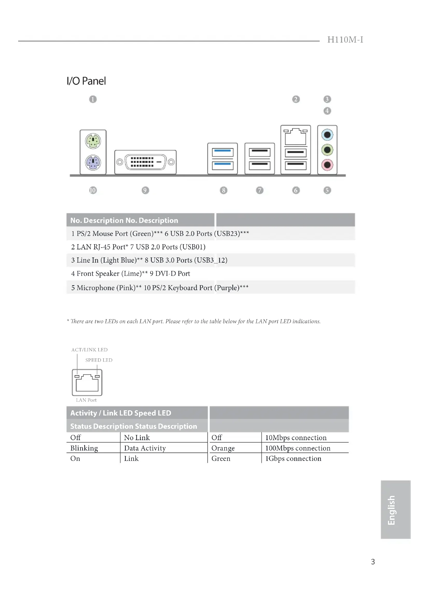
- ere are two LEDs on each LAN port. Please refer to the table below for the LAN port LED indications. Activity / Link LED Speed LED Status Description Status Description Of No Link Of 10Mbps connection Blinking Data Activity Orange 100Mbps connection On Link Green 1Gbps connection ACT/LINK LEDSPEED LEDLAN Port4 English ** To congure 7.1 CH HD Audio, it is required to use an HD front panel audio module and enable the multi- channel audio feature through the audio driver. Please set Speaker Conguration to “7.1 Speaker”in the Realtek HD Audio Manager. Function of the Audio Ports in 7.1-channel Conguration: Port Function Light Blue (Rear panel) Rear Speaker Out Lime (Rear panel) Front Speaker Out Pink (Rear panel) Central /Subwoofer Speaker Out Lime (Front panel) Side Speaker Out *** Support ACPI wake-up function5 English H110M-I
Chapter 1 Introduction
ank you for purchasing ASRock H110M-I motherboard, a reliable motherboard produced under ASRock’s consistently stringent quality control. It delivers excellent performance with robust design conforming to ASRock’s commitment to quality and endurance.
- ASRock H110M-I Support CD
- 2 x Serial ATA (SATA) Data Cables (Optional)
- 1 x I/O Panel Shield Because the motherboard specications and the BIOS soware might be updated, the content of this documentation will be subject to change without notice. In case any modi-cations of this documentation occur, the updated version will be available on ASRock’s website without further notice. If you require technical support related to this mother-board, please visit our website for specic information about the model you are using. You may nd the latest VGA cards and CPU support list on ASRock’s website as well. ASRock website http://www.asrock.com.6 English
- Solid Capacitor design CPU
- Supports CPU up to 95W
- Supports Intel® Turbo Boost 2.0 Technology Chipset
- Dual Channel DDR4 Memory Technology
- Supports DDR4 2133 non-ECC, un-buered memory
- Max. capacity of system memory: 32GB
- Supports NVMe SSD as boot disks
- 1 x PCI Express 2.0 x1 Slot Graphics
- Intel® HD Graphics Built-in Visuals and the VGA outputs can be supported only with processors which are GPU integrated.
- Supports Intel® HD Graphics Built-in Visuals : Intel® Quick Sync Video with AVC, MVC (S3D) and MPEG-2 Full HW Encode1, Intel® InTru
- Supports DVI-D with max. resolution up to 1920x1200 @ 60Hz
- Supports Accelerated Media Codecs: HEVC, VP8, VP9
- Supports HDCP with DVI-D Port
- Supports Full HD 1080p Blu-ray (BD) playback with DVI-D Port7 English H110M-I Audio
- 7.1 CH HD Audio (Realtek ALC887 Audio Codec)
- To congure 7.1 CH HD Audio, it is required to use an HD front panel audio module and enable the multi-channel audio feature through the audio driver.
- Supports Surge Protection (ASRock Full Spike Protection)
- Supports Wake-On-LAN
- Supports Lightning/ESD Protection (ASRock Full Spike Protection)
- Supports Energy Ecient Ethernet 802.3az
- Supports PXE Rear Panel I/O
- 4 x USB 2.0 Ports (Supports ESD Protection (ASRock Full Spike Protection))*
- ACPI wake-up function is supported on USB23 ports only.
- 2 x USB 3.0 Ports (Supports ESD Protection (ASRock Full Spike Protection))
- 1 x RJ-45 LAN Port with LED (ACT/LINK LED and SPEED LED)
- HD Audio Jacks: Line in / Front Speaker / Microphone Storage
- 4 x SATA3 6.0 Gb/s Connectors, support NCQ, AHCI and Hot Plug Connector
- 1 x Chassis Intrusion and Speaker Header
- 1 x Front Panel Audio Connector8 English Please realize that there is a certain risk involved with overclocking, including adjusting the setting in the BIOS, applying Untied Overclocking Technology, or using third-party overclocking tools. Overclocking may aect your system’s stability, or even cause damage to the components and devices of your system. It should be done at your own risk and expense. We are not responsible for possible damage caused by overclocking.
- For detailed product information, please visit our website: http://www.asrock.com
- 1 x USB 2.0 Header (Supports 2 USB 2.0 ports) (Supports ESD Protection (ASRock Full Spike Protection))
- 1 x USB 3.0 Header (Supports 2 USB 3.0 ports) (Supports ESD Protection (ASRock Full Spike Protection)) BIOS Feature
- AMI UEFI Legal BIOS with multilingual GUI support
- ACPI 5.0 Compliant wake up events
- CPU, GT_CPU, DRAM, PCH 1.0V, VCCIO, VCCSA Voltage Multi-adjustment Hardware Monitor
- CPU/Chassis temperature sensing
- CPU/Chassis Fan Tachometer
- CPU/Chassis Quiet Fan (Auto adjust chassis fan speed by CPU temperature)
- CPU/Chassis Fan multi-speed control
- To install Windows® 7 OS, a modied installation disk with xHCI drivers packed into the ISO le is required. Please refer to page 113 for more detailed instructions.
- For the updated Windows® 10 driver, please visit ASRock’s website for details: http://www.asrock.com Certica- tions
- FCC, CE, WHQL9 English H110M-I is is a Micro ATX form factor motherboard. Before you install the motherboard, study the conguration of your chassis to ensure that the motherboard ts into it. Pre-installation Precautions Take note of the following precautions before you install motherboard components or change any motherboard settings.
- Make sure to unplug the power cord before installing or removing the motherboard components. Failure to do so may cause physical injuries and damages to motherboard components.
- In order to avoid damage from static electricity to the motherboard’s components, NEVER place your motherboard directly on a carpet. Also remember to use a grounded wrist strap or touch a safety grounded object before you handle the components.
- Hold components by the edges and do not touch the ICs.
- Whenever you uninstall any components, place them on a grounded anti-static pad or in the bag that comes with the components.
- When placing screws to secure the motherboard to the chassis, please do not over- tighten the screws! Doing so may damage the motherboard.
2.1 Installing the CPU
1. Before you insert the 1151-Pin CPU into the socket, please check if the PnP cap is on the
socket, if the CPU surface is unclean, or if there are any bent pins in the socket. Do not force to insert the CPU into the socket if above situation is found. Otherwise, the CPU will be seriously damaged.
English Please save and replace the cover if the processor is removed. e cover must be placed if you wish to return the motherboard for aer service.13 English H110M-I
2.2 Installing the CPU Fan and Heatsink
is motherboard provides two 288-pin DDR4 (Double Data Rate 4) DIMM slots, and supports Dual Channel Memory Technology. e DIMM only ts in one correct orientation. It will cause permanent damage to the motherboard and the DIMM if you force the DIMM into the slot at incorrect orientation.
1. For dual channel conguration, you always need to install identical (the same brand,
speed, size and chip-type) DDR4 DIMM pairs.
2. It is unable to activate Dual Channel Memory Technology with only one memory module
3. It is not allowed to install a DDR, DDR2 or DDR3 memory module into a DDR4 slot;
otherwise, this motherboard and DIMM may be damaged..15 English H110M-I
ere are 2 PCI Express slots on the motherboard. PCIe slots: PCIE1 (PCIe 2.0 x1 slot) is used for PCI Express x1 lane width cards PCIE2 (PCIe 3.0 x16 slot) is used for PCI Express x16 lane width graphics cards. Before installing an expansion card, please make sure that the power supply is switched o or the power cord is unplugged. Please read the documentation of the expansion card and make necessary hardware settings for the card before you start the installation.17 English H110M-I
2.5 Onboard Headers and Connectors
System Panel Header (9-pin PANEL1) (see p.1, No. 11) Connect the power switch, reset switch and system status indicator on the chassis to this header according to the pin assignments below. Note the positive and negative pins before connecting the cables.
GND RESET#PWRBTN#PLED-PLED+
GND PWRBTN (Power Switch): Connect to the power switch on the chassis front panel. You may congure the way to turn o your system using the power switch. RESET (Reset Switch): Connect to the reset switch on the chassis front panel. Press the reset switch to restart the computer if the computer freezes and fails to perform a normal restart. PLED (System Power LED): Connect to the power status indicator on the chassis front panel. e LED is on when the system is operating. e LED keeps blinking when the system is in S1/S3 sleep state. e LED is o when the system is in S4 sleep state or powered o (S5). HDLED (Hard Drive Activity LED): Connect to the hard drive activity LED on the chassis front panel. e LED is on when the hard drive is reading or writing data. e front panel design may dier by chassis. A front panel module mainly consists of power switch, reset switch, power LED, hard drive activity LED, speaker and etc. When connect- ing your chassis front panel module to this header, make sure the wire assignments and the pin assignments are matched correctly. Onboard headers and connectors are NOT jumpers. Do NOT place jumper caps over these headers and connectors. Placing jumper caps over the headers and connectors will cause permanent damage to the motherboard.18 English Chassis Intrusion and Speaker Header (7-pin SPK_CI1) (see p.1, No. 12) Please connect the chassis intrusion and the chassis speaker to this header. Serial ATA3 Connectors (SATA3_0) (see p.1, No. 7) (SATA3_1) (see p.1, No. 13) (SATA3_2) (see p.1, No. 14) (SATA3_3) (see p.1, No. 15) ese four SATA3 connectors support SATA data cables for internal storage devices with up to
6.0 Gb/s data transfer rate.
Besides four USB 2.0 ports on the I/O panel, there is one header on this motherboard. Each USB
2.0 header can support
two ports. USB 3.0 Header (19-pin USB3_3_4) (see p.1, No. 6)
IntA_PB_D+DummyIntA_PB_D- GND IntA_PB_SSTX+ GND IntA_PB_SSTX-IntA_PB_SSRX+IntA_PB_SSRX-VbusVbus Vbus IntA_PA_SSRX-IntA_PA_SSRX+ GND IntA_PA_SSTX-IntA_PA_SSTX+ GND IntA_PA_D-IntA_PA_D+ Besides two USB 3.0 ports on the I/O panel, there is one header on this motherboard. Each USB
3.0 header can support
is header is for connecting audio devices to the front audio panel. Chassis Fan Connector (4-pin CHA_FAN1) (see p.1, No. 4) GND
FAN_VOLTAGECHA_FAN_SPEEDFAN_SPEED_CONTROL
Please connect fan cables to the fan connector and match the black wire to the ground pin. CPU Fan Connector (4-pin CPU_FAN1) (see p.1, No. 2) GND FAN_VOLTAGE
is motherboard pro- vides a 4-Pin CPU fan (Quiet Fan) connector. If you plan to connect a 3-Pin CPU fan, please connect it to Pin 1-3.
1. High Denition Audio supports Jack Sensing, but the panel wire on the chassis must sup-
port HDA to function correctly. Please follow the instructions in our manual and chassis manual to install your system.
2. If you use an AC’97 audio panel, please install it to the front panel audio header by the
steps below: A. Connect Mic_IN (MIC) to MIC2_L. B. Connect Audio_R (RIN) to OUT2_R and Audio_L (LIN) to OUT2_L. C. Connect Ground (GND) to Ground (GND). D. MIC_RET and OUT_RET are for the HD audio panel only. You don’t need to connect them for the AC’97 audio panel. E. To activate the front mic, go to the “FrontMic” Tab in the Realtek Control panel and adjust “Recording Volume”.20 English ATX Power Connector (24-pin ATXPWR1) (see p.1, No. 5) is motherboard pro- vides a 24-pin ATX power connector. To use a 20-pin ATX power supply, please plug it along Pin 1 and Pin
ATX 12V Power Connector (8-pin ATX12V1) (see p.1, No. 1)
is motherboard pro- vides a 8-pin ATX 12V power connector. TPM Header (17-pin TPMS1) (see p.1, No. 8)
is connector supports Trusted Platform Module (TPM) system, which can securely store keys, digital certicates, passwords, and data. A TPM system also helps enhance network security, protects digital identities, and ensures platform integrity. Clear CMOS Pad (CLRMOS1) (see p.1, No. 10) CLRMOS1 allows you to clear the data in CMOS. To clear CMOS, take out the CMOS battery and short the Clear CMOS Pad.
- ASRock H110M-I-Support-CD
- FCC, CE, WHQL25 H110M-I Deutsch
1.3 Integrierte Stiftleisten und Anschlüsse
RESET#PWRBTN#PLED-PLED+
- FCC, CE, WHQL33 H110M-I Français
1.3 Embases et connecteurs de la carte mère
RESET#PWRBTN#PLED-PLED+
- Supporta Wake-On-LAN
- Supporto la protezione da fulmini/scariche elettrostatiche (ESD) (protezione completa ASRock dai picchi di corrente)
- Supporta Energy Ecient Ethernet 802.3az
- FCC, CE, WHQL41 H110M-I Italiano
1.3 Header e connettori sulla scheda
RESET#PWRBTN#PLED-PLED+
RESET#PWRBTN#PLED-PLED+
- , GT_CPU, DRAM, PCH 1,0 B, VCCIO, VCCSA
- FCC, CE, WHQL57 H110M-I
- Supports Processadores Intel® 6
- 4 x Conectores SATA3 6,0 Gb/s, suporte NCQ, AHCI, Conector a Quente Conector
RESET#PWRBTN#PLED-PLED+
GN D S_P W R D WN#SE R IRQ
- FCC, CE, WHQL73 H110M-I Türkçe
1.3 Ekli Bağlantılar ve Bağlayıcılar
RESET#PWRBTN#PLED-PLED+
- FCC, CE, WHQL81 H110M-I
RESET#PWRBTN#PLED-PLED+
RESET#PWRBTN#PLED-PLED+
RESET#PWRBTN#PLED-PLED+
RESET#PWRBTN#PLED-PLED+
- Microso® Windows® 10 64-bit/8.1 64-bit/7 32-bit/7 64-bit
- FCC, CE, WHQL113 English H110M-I Enabling USB Ports for Windows® 7 Installation Intel® Braswell and Skylake has removed their support for the Enhanced Host Controller Interface (EHCI – USB2.0) and only kept the eXtensible Host Controller Interface (XHCI – USB3.0). Due to that fact that XHCI is not included in the Windows 7 inbox drivers, users may nd it dicult to install Windows 7 operating system because the USB ports on their motherboard won’t work. In order for the USB ports to function properly, please create a Windows® 7 installation disk with the Intel® USB 3.0 eXtensible Host Controller (xHCI) drivers packed into the ISO le. Requirements
- A Windows® 7 installation disk or USB drive
- USB 3.0 drivers (included in the ASRock Support CD or website)
- Win7 USB Patcher (included in the ASRock Support CD or website) Scenarios You have an ODD and PS/2 ports: If there is an optical disc drive, PS/2 ports and PS/2 Keyboard or mouse on your computer, you can skip the instructions below and go ahead to install Windows® 7 OS. You only have an ODD (For Intel Skylake platforms only): If there is an optical disc drive but no PS/2 ports on your computer, please enable the “PS/2 Simulator” option in UEFI SETUP UTILITY > Advanced > USB Conguration, which allows the USB port to function as a PS/2 port, and then you can install the Windows® 7 OS. Please set PS/2 Simulator back to disabled aer the installation. You’ve got nothing: If you do not have an optical disc drive, please nd another computer and follow the instructions below to create a new ISO le with the “Win7 USB Patcher”. en use the new patched Windows® 7 installation USB drive to install Windows® 7 OS.114 English Instructions Step 1 Insert the Windows® 7 installation disk or USB drive to your system. Step 2 Extract the tool (Win7 USB Patcher) and launch it. Step 3 Select the “Win7 Folder” from Step1 by clicking the red circle as shown as the picture below. Step 4 Select the “USB Driver Folder” by clicking the red circle as shown as the picture below. If you are using ASRock’s Support CD for the USB 3.0 driver, please select your CD-ROM.115 English H110M-I Step 5 Select where to save the ISO le by pressing the red circle as shown as the picture below. Step 6 If you want to burn the patched image to a CD, please check “Burn Image” and select “Target Device to Burn”. If not, the patched ISO image will be exported to the destination selected in Step5. en Press “Start” to proceed. Step 7 Now you are able to install Windows® 7 on Braswell or Skylake with the new burned CD. Or please use the patched ISO image to make an OS USB drive to install the OS.Contact Information If you need to contact ASRock or want to know more about ASRock, you’re welcome to visit ASRock’s website at http://www.asrock.com; or you may contact your dealer for further information. For technical questions, please submit a support request form at http://www.asrock.com/support/tsd.asp ASRock Incorporation 2F., No.37, Sec. 2, Jhongyang S. Rd., Beitou District, Taipei City 112, Taiwan (R.O.C.) ASRock EUROPE B.V. Bijsterhuizen 11-11 6546 AR Nijmegen e Netherlands Phone: +31-24-345-44-33 Fax: +31-24-345-44-38 ASRock America, Inc. 13848 Magnolia Ave, Chino, CA91710 U.S.A. Phone: +1-909-590-8308 Fax: +1-909-590-1026