Z97 Extreme6 - Motherboard ASROCK - Free user manual and instructions
Find the device manual for free Z97 Extreme6 ASROCK in PDF.
Download the instructions for your Motherboard in PDF format for free! Find your manual Z97 Extreme6 - ASROCK and take your electronic device back in hand. On this page are published all the documents necessary for the use of your device. Z97 Extreme6 by ASROCK.
USER MANUAL Z97 Extreme6 ASROCK
Version 1.0 Published April 2014 Copyright©2014 ASRock INC. All rights reserved. Copyright Notice: No part of this documentation may be reproduced, transcribed, transmitted, or translated in any language, in any form or by any means, except duplication of documentation by the purchaser for backup purpose, without written consent of ASRock Inc. Products and corporate names appearing in this documentation may or may not be registered trademarks or copyrights of their respective companies, and are used only for identication or explanation and to the owners’ benet, without intent to infringe. Disclaimer: Specications and information contained in this documentation are furnished for informational use only and subject to change without notice, and should not be constructed as a commitment by ASRock. ASRock assumes no responsibility for any errors or omissions that may appear in this documentation. With respect to the contents of this documentation, ASRock does not provide warranty of any kind, either expressed or implied, including but not limited to the implied warranties or conditions of merchantability or tness for a particular purpose. In no event shall ASRock, its directors, ocers, employees, or agents be liable for any indirect, special, incidental, or consequential damages (including damages for loss of prots, loss of business, loss of data, interruption of business and the like), even if ASRock has been advised of the possibility of such damages arising from any defect or error in the documentation or product. is device complies with Part 15 of the FCC Rules. Operation is subject to the following two conditions: (1) this device may not cause harmful interference, and (2) this device must accept any interference received, including interference that may cause undesired operation.
CALIFORNIA, USA ONLY
e Lithium battery adopted on this motherboard contains Perchlorate, a toxic substance controlled in Perchlorate Best Management Practices (BMP) regulations passed by the California Legislature. When you discard the Lithium battery in California, USA, please follow the related regulations in advance. “Perchlorate Material-special handling may apply, see www.dtsc.ca.gov/hazardouswaste/ perchlorate” ASRock Website: http://www.asrock.come terms HDMI™ and HDMI High-Denition Multimedia Interface, and the HDMI logo are trademarks or registered trademarks of HDMI Licensing LLC in the United States and other countries. Manufactured under license under U.S. Patent Nos: 5,956,674; 5,974,380; 6,487,535; 7,003,467 & other U.S. and worldwide patents issued & pending. DTS, the Symbol, & DTS and the Symbol together is a registered trademark & DTS Connect, DTS Interactive, DTS Neo:PC are trademarks of DTS, Inc. Product includes soware. © DTS, Inc., All Rights Reserved.1 English Z97 Extreme6 Intel Z97 DDR3_A2 (64 bit, 240-pin module)DDR3_A1 (64 bit, 240-pin module)DDR3_B2 (64 bit, 240-pin module)DDR3_B1 (64 bit, 240-pin module)ATX 12V1Super I/O
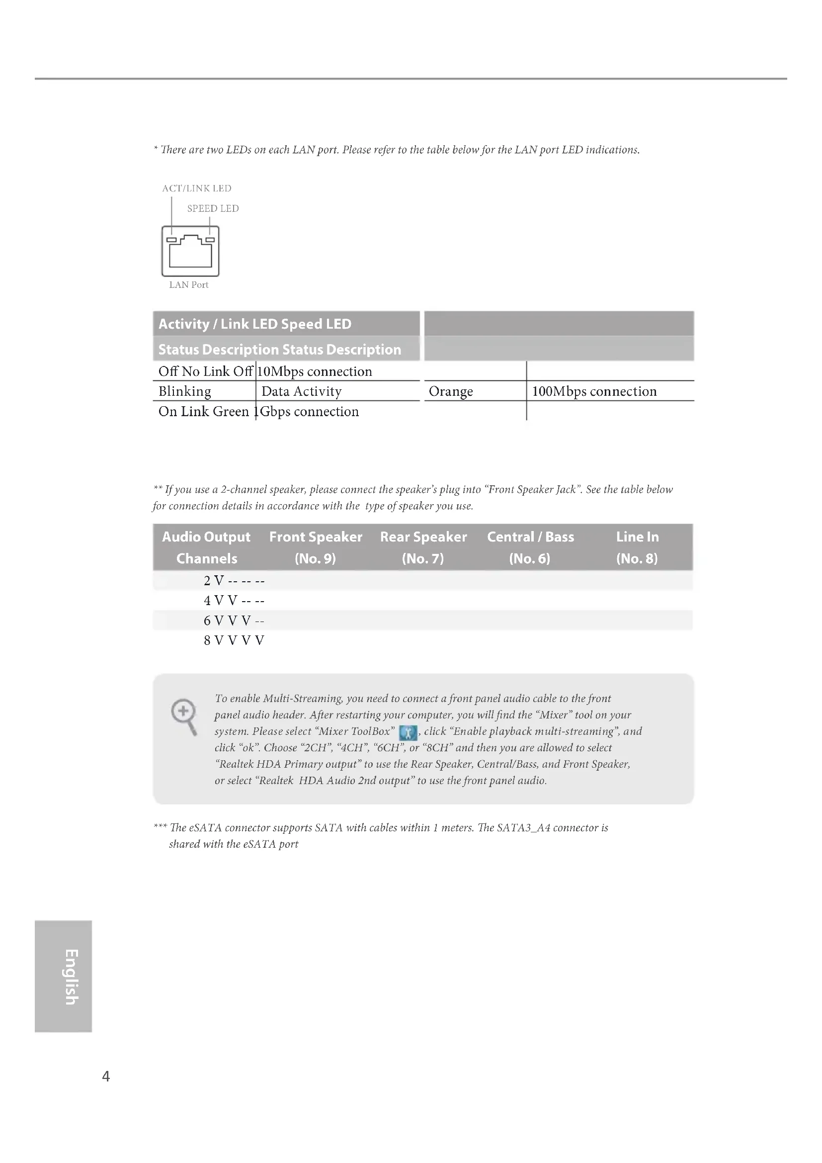
- ere are two LEDs on each LAN port. Please refer to the table below for the LAN port LED indications. Activity / Link LED Speed LED Status Description Status Description O No Link O 10Mbps connection Blinking Data Activity Orange 100Mbps connection On Link Green 1Gbps connection ** If you use a 2-channel speaker, please connect the speaker’s plug into “Front Speaker Jack”. See the table below for connection details in accordance with the type of speaker you use. Audio Output Channels Front Speaker (No. 9) Rear Speaker (No. 7) Central / Bass (No. 6) Line In (No. 8) 2 V -- -- -- 4 V V -- -- 6 V V V -- 8 V V V V *** e eSATA connector supports SATA with cables within 1 meters. e SATA3_A4 connector is shared with the eSATA port To enable Multi-Streaming, you need to connect a front panel audio cable to the front panel audio header. Aer restarting your computer, you will nd the “Mixer” tool on your system. Please select “Mixer ToolBox” , click “Enable playback multi-streaming”, and click “ok”. Choose “2CH”, “4CH”, “6CH”, or “8CH” and then you are allowed to select “Realtek HDA Primary output” to use the Rear Speaker, Central/Bass, and Front Speaker, or select “Realtek HDA Audio 2nd output” to use the front panel audio.
ank you for purchasing ASRock Z97 Extreme6 motherboard, a reliable motherboard produced under ASRock’s consistently stringent quality control. It delivers excellent performance with robust design conforming to ASRock’s commitment to quality and endurance.
1 x I/O Panel Shield
1 x Screw for mini-PCIe Slot Because the motherboard specications and the BIOS soware might be updated, the content of this documentation will be subject to change without notice. In case any modi-cations of this documentation occur, the updated version will be available on ASRock’s website without further notice. If you require technical support related to this mother-board, please visit our website for specic information about the model you are using. You may nd the latest VGA cards and CPU support list on ASRock’s website as well. ASRock website http://www.asrock.com.6 English
XXL Aluminum Alloy Heatsink
Premium Alloy Choke (Reduces 70% core loss compared to iron powder choke)
12K Platinum Caps (100% Japan made high quality conductive polymer capacitors)
12 Power Phase design
Supports Intel® Turbo Boost 2.0 Technology
Supports Intel® K-Series unlocked CPUs
Supports ASRock BCLK Full-range Overclocking Chipset
Dual Channel DDR3 Memory Technology
Max. capacity of system memory: 32GB (see CAUTION)
Supports Intel® Extreme Memory Prole (XMP) 1.3 / 1.2
- If M2_1 slot is occupied, PCIE2 slot will run at x8 mode, and PCIE4 slot will run at x4 mode.
- mini-PCI Express slot is shared with PCIE3 slot.
Intel® HD Graphics Built-in Visuals and the VGA outputs can be supported only with processors which are GPU integrated.
Supports Intel® HD Graphics Built-in Visuals : Intel® Quick Sync Video with AVC, MVC (S3D) and MPEG-2 Full HW Encode1, Intel® InTru
Supports Triple Monitor
Supports HDMI with max. resolution up to 4K x 2K (4096x2160) @ 24Hz
Supports DVI-I with max. resolution up to 1920x1200 @ 60Hz
Supports DisplayPort 1.2 with max. resolution up to 4K x 2K (4096x2160) @ 24Hz or 4K x 2K (3840x2160) @ 60Hz
Supports Auto Lip Sync, Deep Color (12bpc), xvYCC and HBR (High Bit Rate Audio) with HDMI Port (Compliant HDMI monitor is required)
Supports HDCP with DVI-I, HDMI and DisplayPort 1.2 Ports
Supports Full HD 1080p Blu-ray (BD) playback with DVI-I, HDMI and DisplayPort 1.2 Ports8 English Audio
7.1 CH HD Audio with Content Protection (Realtek
Supports Surge Protection (ASRock Full Spike Protection)
Supports Purity Sound™ 2 - Nichicon Fine Gold Series Audio Caps - 115dB SNR DAC with Dierential Amplier - TI® NE5532 Premium Headset Amplier (Supports up to 600 Ohms headsets) - Direct Drive Technology - EMI Shielding Cover - PCB Isolate Shielding
Supports DTS Connect LAN
1 x Intel® I218V (Gigabit LAN PHY 10/100/1000 Mb/s)
Supports Intel® Remote Wake Technology (on Intel® I218V)
Supports Wake-On-WAN (on Realtek RTL8111GR)
Supports Wake-On-LAN
Supports Lightning/ESD Protection (ASRock Full Spike Protection)
Supports LAN Cable Detection (on Realtek RTL8111GR)
Supports Energy Ecient Ethernet 802.3az
Supports PXE Rear Panel I/O
2 x RJ-45 LAN Ports with LED (ACT/LINK LED and SPEED LED)
HD Audio Jacks: Rear Speaker / Central / Bass / Line in / Front Speaker / Microphone Storage
6 x SATA3 6.0 Gb/s Connectors by Intel® Z97, support RAID (RAID 0, RAID 1, RAID 5, RAID 10, Intel Rapid Storage Technology 13 and Intel Smart Response Technology), NCQ, AHCI, Hot Plug and ASRock HDD Saver Technology
4 x SATA3 6.0 Gb/s Connectors by ASMedia ASM1061, support NCQ, AHCI, Hot Plug and ASRock HDD Saver Technology (SATA3_A4 connector is shared with the eSATA port)
1 x SATA Express Connector (shared with SATA3_4, SATA3_5 and M.2_SSD (NGFF) Socket 3 (M2_2))
- Support to be announced
1 x eSATA Connector by ASMedia ASM1061, supports NCQ, AHCI, Hot Plug and Port Multiplier
2 x CPU Fan Connectors (1 x 4-pin, 1 x 3-pin)
3 x Chassis Fan Connectors (1 x 4-pin, 2 x 3-pin)
1 x Power Fan Connector (3-pin)
1 x 8 pin 12V Power Connector (Hi-Density Power Connector)
1 x Front Panel Audio Connector
1 x underbolt AIC Connector
2 x USB 2.0 Headers (support 4 USB 2.0 ports) (Supports ESD Protection (ASRock Full Spike Protection))
2 x USB 3.0 Headers (support 4 USB 3.0 ports) (Supports ESD Protection (ASRock Full Spike Protection))
1 x Dr. Debug with LED
1 x Power Switch with LED
1 x Reset Switch with LED
Supports Secure Backup UEFI Technology
ACPI 1.1 Compliant wake up events
Drivers, Utilities, AntiVirus Soware (Trial Version), Google Chrome Browser and Toolbar, Start8 (30 days trial), Kloudian Orbweb.ME Professional Hardware Monitor
CPU/Chassis temperature sensing
CPU/Chassis Quiet Fan (Auto adjust chassis fan speed by CPU temperature)
CPU/Chassis Fan multi-speed control
ErP/EuP Ready (ErP/EuP ready power supply is required)11 English Z97 Extreme6 Please realize that there is a certain risk involved with overclocking, including adjusting the setting in the BIOS, applying Untied Overclocking Technology, or using third-party overclocking tools. Overclocking may aect your system’s stability, or even cause damage to the components and devices of your system. It should be done at your own risk and expense. We are not responsible for possible damage caused by overclocking.
- For detailed product information, please visit our website: http://www.asrock.com Due to limitation, the actual memory size may be less than 4GB for the reservation for sys- tem usage under Windows® 32-bit operating systems. Windows® 64-bit operating systems do not have such limitations. You can use ASRock XFast RAM to utilize the memory that Windows® cannot use.12 English
ASRock Super Alloy is motherboard is specially designed with Super Alloy Technology for faster, stabler, and more durable performance, including XXL Aluminum Alloy Heatsink, Premium Alloy Choke, Dual-Stack MOSFET, NexFET
MOSFET, 12K Platinum Cap, and Sapphire Black PCB. ASRock Ultra M.2 (PCIe Gen3 x4) e world's fastest Ultra M.2 socket that shares PCIe 3.0 x4 bandwidth directly from the CPU. Unlike Gen1 M.2, Gen3 x4 M.2 works up to 6X faster! It also supports all lengths of M.2 devices (30mm, 42mm, 60mm, 80mm, and 110mm). Feel free to install your M.2 devices without any trouble. ASRock HDD Saver Technology A power supply connector placed near the SATA ports. It supports up to two SATA HDDs. Users are able to switch on and o the connected HDDs via soware when needed. is design secures more privacy, saves more energy, and extends the HDDs' lifespans.
ASRock Full Spike Protection A technology consists of 3 unique features: Surge Protection, Lightning Protection, and ESD Protection. By adding specialized ICs and reworking circuits, the onboard USB ports, LAN ports, and MOSFETs in critical areas are all well protected from surges, spikes, and electrostatic discharge. ASRock Cloud ASRock partners with Kloudian to make your mobile devices connect to your PC seamlessly! ASRock Cloud allows you to get connected with your PC’s les, music, photos, and video clips remotely with tablets anytime, anywhere.
- OrbWeb ME is provided by a third party. Restriction may apply and the oer is subject to change, termination or discontinuation by the third party without prior notice. Please visit the website for further details: http://www.asrock.com/feature/cloud/index.html
ASRock APP Shop ASRock APP Shop is designed for your convenience. We provide various apps and support soware for users to download on the mainpage of APP Shop. You can eas- ily optimize your system and keep your motherboard up to date with a few clicks.13 English Z97 Extreme6 ASRock A-Tuning A-Tuning is ASRock’s multi purpose soware suite with a new interface, more new features and improved utilities.
ASRock Disk Health Report Displaying detailed HDD information. You can check the model names, capacities, temperatures, SMART info, health status, and other information of your HDDs here.
ASRock USB Key In a world where time is money, why waste precious time everyday typing usernames to log in to Windows? Why should we even bother memorizing those foot long passwords? Just plug in the USB Key and let your computer log in to windows automatically! ASRock APP Charger Simply by installing the ASRock APP Charger makes your iPhone/iPad/iPod Touch charge up to 40% faster than before on your computer. ASRock APP Charger allows you to quickly charge many Apple devices simultaneously and even supports continuous charging when your PC enters into Standby mode (S1), Suspend to RAM (S3), hibernation mode (S4) or power o (S5).
ASRock XFast LAN ASRock XFast LAN provides faster internet access, which includes the benets listed below. LAN Application Prioritization: You can congure your application’s priority ideally and add new programs to the list. Lower Latency in Game: Aer setting online game’s priority higher, it can lower the latency in games. Trac Shaping: You can watch Youtube HD videos and download simultaneously. Real- Time Analysis of Your Data: With the status window, you can easily recognize which data streams you are currently transferring.
ASRock XFast RAM ASRock XFast RAM is included in A-Tuning. It fully utilizes the memory space that cannot be used under Windows® 32-bit operating systems. ASRock XFast RAM shortens the loading time of previously visited websites, making web surng faster than ever. And it also boosts the speed of Adobe Photoshop 5 times faster. Another advantage of ASRock XFast RAM is that it reduces the frequency of accessing your SSDs or HDDs in order to extend their lifespan.14 English
ASRock Full HD UEFI All new Full HD UEFI with a resolution of 1920 x 1080. e UEFI should be designed easy to use and setup. With Full HD resolution, now it is much easier and clearer for all users to setup, optimize, and update their BIOS. ASRock My Favorites in UEFI Another handy design in ASRock UEFI. You can select and add commonly used BIOS options to "My Favorites" by clicking the asterisk icon at the upper right hand corner of the screen. ese chosen options will show up on "My Favorites" page in UEFI.
ASRock UEFI Guide Need help to optimize your UEFI setting? Got lost among UEFI pages? Just select “UEFI Guide”! e tutorial will explain every detailed setting and help you to cus- tomize your UEFI easily.
ASRock Instant Flash ASRock Instant Flash is a BIOS ash utility embedded in Flash ROM. is conve- nient BIOS update tool allows you to update the system BIOS in a few clicks without preparing an additional oppy diskette or other complicated ash utility. Just save the new BIOS le to your USB storage and launch this tool by pressing <F6> or <F2> during POST to enter the BIOS setup menu to access ASRock Instant Flash. Please be noted that the USB ash drive or hard drive must use FAT32/16/12 le system.
ASRock Crashless BIOS ASRock Crashless BIOS allows users to update their BIOS without fear of failing. If power loss occurs during the BIOS updating process, ASRock Crashless BIOS will automatically nish the BIOS update procedure aer regaining power. Please note that BIOS les need to be placed in the root directory of your USB disk. Only USB 2.0 ports support this feature.
ASRock OMG (Online Management Guard) Administrators are able to establish an internet curfew or restrict internet access at specied times via OMG. You may schedule the starting and ending hours of internet access granted to other users. In order to prevent users from bypassing OMG, guest accounts without permission to modify the system time are required.
ASRock UEFI System Browser ASRock System Browser shows the overview of your current PC and the devices connected.
ASRock UEFI Tech Service Contact ASRock Tech Service by sending a support request from the UEFI setup utility if you are having trouble with your PC.
ASRock Dehumidier Function Users may prevent motherboard damages due to dampness by enabling “Dehumidier Function”. When enabling Dehumidier Function, the computer will power on automatically to dehumidify the system aer entering S4/S5 state.
ASRock Easy RAID Installer ASRock Easy RAID Installer can help you to copy the RAID driver from the support CD to your USB storage device. Aer copying the RAID driver to your USB storage device, please change “SATA Mode” to “RAID”, then you can start installing the OS in RAID mode.
ASRock Easy Driver Installer For users that don’t have an optical disk drive to install the drivers from our support CD, Easy Driver Installer is a handy tool in the UEFI that installs the LAN driver to your system via an USB storage device, then downloads and installs the other required drivers automatically.16 English is is an ATX form factor motherboard. Before you install the motherboard, study the conguration of your chassis to ensure that the motherboard ts into it. Pre-installation Precautions Take note of the following precautions before you install motherboard components or change any motherboard settings.
Make sure to unplug the power cord before installing or removing the motherboard components. Failure to do so may cause physical injuries and damages to motherboard components.
In order to avoid damage from static electricity to the motherboard’s components, NEVER place your motherboard directly on a carpet. Also remember to use a grounded wrist strap or touch a safety grounded object before you handle the components.
Hold components by the edges and do not touch the ICs.
Whenever you uninstall any components, place them on a grounded anti-static pad or in the bag that comes with the components.
When placing screws to secure the motherboard to the chassis, please do not over- tighten the screws! Doing so may damage the motherboard.
Chapter 2 Installation17
English Z97 Extreme6
2.1 Installing the CPU
1. Before you insert the 1150-Pin CPU into the socket, please check if the PnP cap is on the
socket, if the CPU surface is unclean, or if there are any bent pins in the socket. Do not force to insert the CPU into the socket if above situation is found. Otherwise, the CPU will be seriously damaged.
English Z97 Extreme6 Please save and replace the cover if the processor is removed. e cover must be placed if you wish to return the motherboard for aer service.20 English
2.2 Installing the CPU Fan and Heatsink
is motherboard provides four 240-pin DDR3 (Double Data Rate 3) DIMM slots, and supports Dual Channel Memory Technology. Dual Channel Memory Conguration e DIMM only ts in one correct orientation. It will cause permanent damage to the motherboard and the DIMM if you force the DIMM into the slot at incorrect orientation. Priority DDR3_A1 DDR3_A2 DDR3_B1 DDR3_B2 1 Populated Populated 2 Populated Populated 3 Populated Populated Populated Populated
1. For dual channel conguration, you always need to install identical (the same brand,
speed, size and chip-type) DDR3 DIMM pairs.
2. It is unable to activate Dual Channel Memory Technology with only one or three memory
3. It is not allowed to install a DDR or DDR2 memory module into a DDR3 slot; otherwise,
this motherboard and DIMM may be damaged.22 English
ere are 5 PCI Express slots and 1 mini-PCI Express slot on the motherboard. PCIe slots: PCIE1 (PCIe 2.0 x1 slot) is used for PCI Express x1 lane width cards. PCIE2 (PCIe 3.0 x16 slot) is used for PCI Express x16 lane width graphics cards. PCIE3 (PCIe 2.0 x1 slot) is used for PCI Express x1 lane width cards. PCIE4 (PCIe 3.0 x16 slot) is used for PCI Express x8 lane width graphics cards. PCIE5 (PCIe 3.0 x16 slot) is used for PCI Express x2 lane width graphics cards. mini-PCIe slot: MINI_PCIE1 (mini-PCIe slot) is used for WiFi module.
- e mini-PCI Express slot is shared with PCIE3 slot. PCIe Slot Congurations PCIE2 PCIE4 Single Graphics Card x16 N/A Two Graphics Cards in CrossFireX
Mode x8 x8 For a better thermal environment, please connect a chassis fan to the motherboard’s chas- sis fan connector (CHA_FAN1, CHA_FAN2 or CHA_FAN3) when using multiple graphics cards. Before installing an expansion card, please make sure that the power supply is switched o or the power cord is unplugged. Please read the documentation of the expansion card and make necessary hardware settings for the card before you start the installation.24 English
e illustration shows how jumpers are setup. When the jumper cap is placed on the pins, the jumper is “Short”. If no jumper cap is placed on the pins, the jumper is “Open”. e illustration shows a 3-pin jumper whose pin1 and pin2 are “Short” when a jumper cap is placed on these 2 pins. Clear CMOS Jumper (CLRCMOS1) (see p.1, No. 9) CLRCMOS1 allows you to clear the data in CMOS. To clear and reset the system parameters to default setup, please turn o the computer and unplug the power cord from the power supply. Aer waiting for 15 seconds, use a jumper cap to short pin2 and pin3 on CLRCMOS1 for 5 seconds. However, please do not clear the CMOS right aer you update the BIOS. If you need to clear the CMOS when you just nish updating the BIOS, you must boot up the system rst, and then shut it down before you do the clear-CMOS action. Please be noted that the password, date, time, and user default prole will be cleared only if the CMOS battery is removed. Clear CMOSDefault e Clear CMOS Switch has the same function as the Clear CMOS jumper.25 English Z97 Extreme6
2.6 Onboard Headers and Connectors
System Panel Header (9-pin PANEL1) (see p.1, No. 23) Connect the power switch, reset switch and system status indicator on the chassis to this header according to the pin assignments below. Note the positive and negative pins before connecting the cables. GND
RESET#PWRBTN#PLED-PLED+
GND PWRBTN (Power Switch): Connect to the power switch on the chassis front panel. You may congure the way to turn o your system using the power switch. RESET (Reset Switch): Connect to the reset switch on the chassis front panel. Press the reset switch to restart the computer if the computer freezes and fails to perform a normal restart. PLED (System Power LED): Connect to the power status indicator on the chassis front panel. e LED is on when the system is operating. e LED keeps blinking when the system is in S1/S3 sleep state. e LED is o when the system is in S4 sleep state or powered o (S5). HDLED (Hard Drive Activity LED): Connect to the hard drive activity LED on the chassis front panel. e LED is on when the hard drive is reading or writing data. e front panel design may dier by chassis. A front panel module mainly consists of power switch, reset switch, power LED, hard drive activity LED, speaker and etc. When connect- ing your chassis front panel module to this header, make sure the wire assignments and the pin assignments are matched correctly. Onboard headers and connectors are NOT jumpers. Do NOT place jumper caps over these headers and connectors. Placing jumper caps over the headers and connectors will cause permanent damage to the motherboard.26 English Power LED Header (3-pin PLED1) (see p.1, No. 18) Please connect the chassis power LED to this header
indicate the system’s power status. Serial ATA3 Connectors (SATA3_0_3: see p.1, No. 12) (SATA3_1_4: see p.1, No. 13) (SATA3_2_5: see p.1, No. 14) (SATA3_A1_A2: see p.1, No. 11) (SATA3_A3_A4: see p.1, No. 10) ese ten SATA3 connectors support SATA data cables for internal storage devices with up to 6.0 Gb/s data transfer rate. If the eSATA port on the rear I/O has been connected, the internal SATA3_A4 will not function. e SATA3_4, SATA3_5 are shared with the SATA Express connector. To minimize the boot time, use Intel® Z97 SATA ports (SATA3_0) for your bootable devices. Serial ATA Express Connector (SATAE_1: see p.1, No. 15) Please connect either SATA or PCIe storage devices to this connector. e SATA Express connector is shared with the SATA3_4, SATA3_5 and the M.2_SSD (NGFF) Socket 3 (M2_2). *e SATA Express interface is a combination of SATAE_1, SATA3_4, and SATA3_5.
USB 2.0 Headers (9-pin USB2_3) (see p.1, No. 25) (9-pin USB4_5) (see p.1, No. 26) ere are two headers and one port on this motherboard. Each USB
2.0 header can support
two ports. (USB1) (see p.1, No. 24) USB 3.0 Headers (19-pin USB3_4_5) (see p.1, No. 8) (19-pin USB3_6_7) (see p.1, No. 27) Besides six USB 3.0 ports on the I/O panel, there are two headers on this motherboard. Each USB
3.0 header can support
two ports. Front Panel Audio Header (9-pin HD_AUDIO1) (see p.1, No. 32) is header is for connecting audio devices to the front audio panel. Chassis Speaker Header (4-pin SPEAKER1) (see p.1, No. 17) Please connect the chassis speaker to this header.
+5V DUMMY DUMMY SPEAKER28 English Chassis and Power Fan Connectors (4-pin CHA_FAN1) (see p.1, No. 16) (3-pin CHA_FAN2) (see p.1, No. 29) (3-pin CHA_FAN3) (see p.1, No. 34) (3-pin PWR_FAN1) (see p.1, No. 6) Please connect fan cables to the fan connectors and match the black wire to the ground pin. CPU Fan Connectors (4-pin CPU_FAN1) (see p.1, No. 2) (3-pin CPU_FAN2) (see p.1, No. 3) is motherboard pro- vides a 4-Pin CPU fan (Quiet Fan) connector. If you plan to connect a 3-Pin CPU fan, please connect it to Pin 1-3. GND +12V
1. High Denition Audio supports Jack Sensing, but the panel wire on the chassis must sup-
port HDA to function correctly. Please follow the instructions in our manual and chassis manual to install your system.
2. If you use an AC’97 audio panel, please install it to the front panel audio header by the
steps below: A. Connect Mic_IN (MIC) to MIC2_L. B. Connect Audio_R (RIN) to OUT2_R and Audio_L (LIN) to OUT2_L. C. Connect Ground (GND) to Ground (GND). D. MIC_RET and OUT_RET are for the HD audio panel only. You don’t need to connect them for the AC’97 audio panel. E. To activate the front mic, go to the “FrontMic” Tab in the Realtek Control panel and adjust “Recording Volume”.29 English Z97 Extreme6
ATX Power Connector (24-pin ATXPWR1) (see p.1, No. 7) is motherboard pro- vides a 24-pin ATX power connector. To use a 20-pin ATX power supply, please plug it along Pin 1 and Pin
ATX 12V Power Connector (8-pin ATX12V1) (see p.1, No. 1) is motherboard pro- vides an 8-pin ATX 12V power connector. To use a 4-pin ATX power supply, please plug it along Pin 1 and Pin 5. PCIe Power Connector (4-pin PCIE_PWR1) (see p.1, No. 30) Please connect a 4 pin molex power cable to this connector when more than three graphics cards are installed. HDD Saver Connector (4-pin SATA_PWR _1) (see p.1, No. 22) Please connect the HDD Saver Cable to this connector to manage the power state of HDD. underbolt AIC Connector (5-pin TB1) (see p.1, No. 28) Please connect a underbolt™ add-in card (AIC) to this connector via the GPIO cable. Serial Port Header (9-pin COM1) (see p.1, No. 31) is COM1 header supports a serial port module.
CCTS#1RRTS#1DDSR#1DDTR#1RRXD1
RRI#130 English TPM Header (17-pin TPMS1) (see p.1, No. 33) is connector supports Trusted Platform Module (TPM) system, which can securely store keys, digital certicates, passwords, and data. A TPM system also helps enhance network security, protects digital identities, and ensures platform integrity.
e motherboard has four smart switches: Power Switch, Reset Switch, Clear CMOS Switch and one BIOS Selection Switch, allowing users to quickly turn on/o the system, reset the system, clear the CMOS values or boot from dierent BIOS.Power Switch(PWRBTN)(see p.1, No. 20)Power Switch allows users to quickly turn on/o the system.Reset Switch(RSTBTN)(see p.1, No. 21)Reset Switch allows users to quickly reset the system.Clear CMOS Switch(CLRCBTN)(see p.3, No. 16)Clear CMOS Switch allows users to quickly clear the CMOS values.BIOS Selection Switch (BIOS_SEL1) (see p.1 No. 19)BIOS Selection Switch allows the system to boot from either BIOS A or BIOS B. Power Reset is function is workable only when you power o your computer and unplug the power supply.
is motherboard has two BIOS chips, a primary BIOS (BIOS_A) and a backup BIOS (BIOS_B), which enhances the safety and stability of your system. Normally, the system will work on the primary BIOS. However, if the primary BIOS is corrupted or damaged, just ip the BIOS Selection Switch to “B”, then the backup BIOS will take over on the next system boot. Aer that, use “Secure Backup UEFI” in the UEFI Setup Utility to duplicate a working copy of the BIOS les to the primary BIOS to ensure normal system operation. For safety issues, users are not able to update the backup BIOS manually. Users may refer to the BIOS LEDs (BIOS_A_LED or BIOS_B_LED) to identify which BIOS is currently activated.32 English
Dr. Debug is used to provide code information, which makes troubleshooting even easier. Please see the diagrams below for reading the Dr. Debug codes. Code Description 00 Please check if the CPU is installed correctly and then clear CMOS. 0d Problem related to memory, VGA card or other devices. Please clear CMOS, re-install the memory and VGA card, and remove other USB, PCI devices.
(except 0d), 5A- 60 Problem related to memory. Please re-install the CPU and memory then clear CMOS. If the problem still exists, please install only one memory module or try using other memory modules. 55 e Memory could not be detected. Please re-install the memory and CPU. If the problem still exists, please install only one memory module or try using other memory modules.
92 - 99 Problem related to PCI-E devices. Please re-install PCI-E
devices or try installing them in other slots. If the problem still exists, please remove all PCI-E devices or try using another VGA card. A0 - A7 Problem related to IDE or SATA devices. Please re-install IDE and SATA devices. If the problem still exists, please clear CMOS and try removing all SATA devices. b0 Problem related to memory. Please re-install the CPU and memory. If the problem still exists, please install only one memory module or try using other memory modules.33 English Z97 Extreme6 b4 Problem related to USB devices. Please try removing all USB devices. b7 Problem related to memory. Please re-install the CPU and memory then clear CMOS. If the problem still exists, please install only one memory module or try using other memory modules. d6 e VGA could not be recognized. Please clear CMOS and try re-installing the VGA card. If the problem still exists, please try installing the VGA card in other slots or use other VGA cards. d7 e Keyboard and mouse could not be recognized. Please try re-installing the keyboard and mouse. d8 Invalid Password. FF Please check if the CPU is installed correctly and then clear CMOS.34 English
2.9 M.2_SSD (NGFF) Module Installation Guide
The M.2, also known as the Next Generation Form Factor (NGFF), is a small size and versatile card edge connector that aims to replace mPCIe and mSATA. The Ultra M.2 Socket (M2_1), supports M.2 PCI Express module up to Gen3 x4 (32 Gb/s). e M.2_SSD (NGFF) Socket 3 (M2_2) can accommodate either a M.2 SATA3 6.0 Gb/s module or a M.2 PCI Express module up to Gen 2 x2 (10 Gb/s). Please be noted that the M.2_SSD (NGFF) Socket 3 (M2_2) is shared with the SATA Express connector; you can only choose either the M.2_SSD (NGFF) Socket 3 (M2_2) or the SATA Express connector to use. *e M.2_SSD (NGFF) Socket 3 supports SSD drives. Please note that the WiFi or other non-SSD M.2 modules are not supported. Installing the M.2_SSD (NGFF) Module Step 1 Prepare a M.2_SSD (NGFF) module and the screw.
Step 3 Move the stando based on the module type and length. e stando is placed at the nut location D by default. Skip Step 3 and 4 and go straight to Step 5 if you are going to use the default nut. Otherwise, release the stando by hand. BCDE
Step 4 Peel o the yellow protective lm on the nut to be used. Hand tighten the stando into the desired nut location on the motherboard.
Step 6 Tighten the screw with a screwdriver to secure the module into place. Please do not overtighten the screw as this might damage the module. M.2_SSD (NGFF) Module Support List For the latest updates of M.2_SSD (NFGG) module support list, please visit our website for details: http://www.asrock.com37 English Z97 Extreme6
2.10 HDD Saver Cable Installation Guide
The HDD Saver Connector on this motherboard allows you to switch on and off the connected HDDs via soware when needed. is design secures more privacy, saves more energy, and extends the HDDs' lifespans. Please follow the steps below to install the HDD Saver Cable. Connection Diagram *e diagram shown here is for reference only.
1. Connect one end of the HDD Saver Cable to the HDD Saver Connector (SATA_
PWR_1) placed near the SATA ports. en connect the SATA power connector(s) to your SATA HDD(s).
- e HDD Saver Connector supports up to two SATA HDDs.
2. Connect one end of the SATA data cable to a SATA port on the motherboard. en
connect the other end to your SATA HDD(s).
RESET#PWRBTN#PLED-PLED+
CCTS#1RRTS#1DDSR#1DDTR#1RRXD1
- 1 x Intel® I218V (Gigabit LAN PHY 10/100/1000 Mb/s)
RESET#PWRBTN#PLED-PLED+
CCTS#1RRTS#1DDSR#1DDTR#1RRXD1
- Supporta Intel® Extreme Memory Prole (XMP)1.3/1.2
- Supporta DTS Connect LAN
- 1 x Intel® I218V (Gigabit LAN PHY 10/100/1000 Mb/s)
- Supporta Wake-On-LAN
- Supporta Energy Ecient Ethernet 802.3az
RESET#PWRBTN#PLED-PLED+
CCTS#1RRTS#1DDSR#1DDTR#1RRXD1
- 1 Intel® I218V (Gigabit LAN PHY 10/100/1000 Mb/s)
- 1 conector underbolt AIC
RESET#PWRBTN#PLED-PLED+
CCTS#1RRTS#1DDSR#1DDTR#1RRXD1
RESET#PWRBTN#PLED-PLED+
CCTS#1RRTS#1DDSR#1DDTR#1RRXD1
- 1 x Intel® I218V (Gigabit LAN PHY 10/100/1000 Mb/s)
- 1 x Conector underbolt AIC
RESET#PWRBTN#PLED-PLED+
CCTS#1RRTS#1DDSR#1DDTR#1RRXD1
- 1 x Intel® I218V (Gigabit LAN PHY 10/100/1000 Mb/s)
RESET#PWRBTN#PLED-PLED+
CCTS#1RRTS#1DDSR#1DDTR#1RRXD1
RESET#PWRBTN#PLED-PLED+
CCTS#1RRTS#1DDSR#1DDTR#1RRXD1
RESET#PWRBTN#PLED-PLED+
CCTS#1RRTS#1DDSR#1DDTR#1RRXD1
Deep Color (12bpc), xvYCC
- 1 x Intel® I218V (Gigabit LAN PHY 10/100/1000 Mb/s)
Voltage Multi-adjustment
RESET#PWRBTN#PLED-PLED+
Trusted Platform Module
CCTS#1RRTS#1DDSR#1DDTR#1RRXD1
- 1 x Intel® I218V (Gigabit LAN PHY 10/100/1000 Mb/s)
RESET#PWRBTN#PLED-PLED+
CCTS#1RRTS#1DDSR#1DDTR#1RRXD1
- 1xIntel®I218V(GigabitLANPHY10/100/1000Mb/s)