Fatal1ty Z77 Professional - Motherboard ASROCK - Free user manual and instructions
Find the device manual for free Fatal1ty Z77 Professional ASROCK in PDF.

Download the instructions for your Motherboard in PDF format for free! Find your manual Fatal1ty Z77 Professional - ASROCK and take your electronic device back in hand. On this page are published all the documents necessary for the use of your device. Fatal1ty Z77 Professional by ASROCK.
USER MANUAL Fatal1ty Z77 Professional ASROCK
Fatal1ty Z77 Professional Series Motherboard
English Who knew that at age 19, I would be a World Champion PC gamer. When I was 13, I actually played competitive billiards in professional tournaments and won four or five games off guys who played at the highest level. I actually thought of making a career of it, but at that young age situations change rapidly. Because I’ve been blessed with great hand-eye coordination and a grasp of mathematics (an important element in video gaming) I gravitated to that activity. GOING PRO I started professional gaming in 1999 when I entered the CPL (Cyberathlete Professional League) tournament in Dallas and won $4,000 for coming in third place. Emerging as one of the top players in the United States, a company interested in sponsoring me ew me to Sweden to compete against the top 12 players in the world. I won 18 straight games, lost none, and took rst place, becoming the number one ranked Quake III player in the world in the process. Two months later I followed that success by traveling to Dallas and defending my title as the world’s best Quake III player, winning the $40,000 grand prize. From there I entered competitions all over the world, including Singapore, Korea, Germany, Australia, Holland and Brazil in addition to Los Angeles, New York and St. Louis. WINNING STREAK I was excited to showcase my true gaming skills when defending my title as CPL Champion of the year at the CPL Winter 2001 because I would be competing in a totally different first person shooter (fps) game, Alien vs. Predator II. I won that competition and walked away with a new car. The next year I won the same title playing Unreal Tournament 2003, becoming the only three-time CPL champion of the year. And I did it playing a different game each year, something no one else has ever done and a feat of which I am extremely proud. At QuakeCon 2002, I faced off against my rival ZeRo4 in one of the most highly anticipated matches of the year, winning in a 14 to (-1) killer victory. Competing at Quakecon 2004, I became the World’s 1st Doom3 Champion by defeating Daler in a series of very challenging matches and earning $25,000 for the victory. Since then Fatal1ty has traveled the globe to compete against the best in the world, winning prizes and acclaim, including the 2005 CPL World Tour Championship in New York City for a $150,000 rst place triumph. In August 2007, Johnathan was awarded the rst ever Lifetime Achievement Award in the four year history of the eSports-Award for “showing exceptional sportsmanship, taking part in shaping eSports into what it is today and for being the prime representative of this young sport. He has become the gurehead for eSports worldwide”. Fatal1ty Story2 Fatal1ty Z77 Professional Series Motherboard English LIVIN’ LARGE Since my rst big tournament wins, I have been a “Professional Cyberathlete”, traveling the world and livin’ large with lots of International media coverage on outlets such as MTV, ESPN and a 60 Minutes segment on CBS to name only a few. It's unreal - it's crazy. I’m living a dream by playing video games for a living. I’ve always been athletic and took sports like hockey and football very seriously, working out and training hard. This discipline helps me become a better gamer and my drive to be the best has opened the doors necessary to become a professional. A DREAM Now, another dream is being realized – building the ultimate gaming computer, made up of the best parts under my own brand. Quality hardware makes a huge difference in competitions…a couple more frames per second and everything gets really nice. It’s all about getting the computer processing faster and allowing more uid movement around the maps. My vision for Fatal1ty hardware is to allow gamers to focus on the game without worrying about their equipment, something I’ve preached since I began competing. I don’t want to worry about my equipment. I want to be there – over and done with - so I can focus on the game. I want it to be the fastest and most stable computer equipment on the face of the planet, so quality is what Fatal1ty Brand products represent. Johnathan “Fatal1ty” Wendel The Fatal1ty name, Fatal1ty logos and the Fatal1ty likeness are registered trademarks of Fatal1ty, Inc., and are used under license. © 2012 Fatal1ty, Inc. All rights reserved. All other trademarks are the property of their respective owners.3 English Copyright Notice: No part of this manual may be reproduced, transcribed, transmitted, or translated in any language, in any form or by any means, except duplication of documentation by the pur- chaser for backup purpose. Products and corporate names appearing in this manual may or may not be registered trademarks or copyrights of their respective companies, and are used only for identica- tion or explanation and to the owners’ benet, without intent to infringe. Disclaimer: Specications and information contained in this manual are furnished for informational use only and subject to change without notice, and should not be constructed as a com- mitment by us. We assumes no responsibility for any errors or omissions that may appear in this manual. With respect to the contents of this manual, We do not provide warranty of any kind, ei- ther expressed or implied, including but not limited to the implied warranties or conditions of merchantability or tness for a particular purpose. In no event shall we, its directors, ofcers, employees, or agents be liable for any indirect, special, incidental, or consequential damages (including damages for loss of prots, loss of business, loss of data, interruption of business and the like), even if we have been ad- vised of the possibility of such damages arising from any defect or error in the manual or product. This device complies with Part 15 of the FCC Rules. Operation is subject to the following two conditions: (1) this device may not cause harmful interference, and (2) this device must accept any interference received, including interference that may cause undesired operation.
CALIFORNIA, USA ONLY
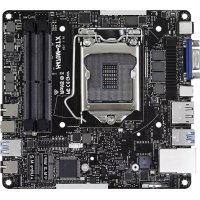
The Lithium battery adopted on this motherboard contains Perchlorate, a toxic substance controlled in Perchlorate Best Management Practices (BMP) regulations passed by the California Legislature. When you discard the Lithium battery in California, USA, please follow the related regulations in advance. “Perchlorate Material-special handling may apply, see www.dtsc.ca.gov/hazardouswaste/perchlorate” The Fatal1ty name, Fatal1ty logos and the Fatal1ty likeness are registered trademarks of Fatal1ty, Inc., and are used under license. © 2012 Fatal1ty, Inc. All rights reserved. All other trademarks are the property of their respective owners. Fatal1ty website: www.fatal1ty.com The terms HDMI™ and HDMI High-Denition Multimedia Interface, and the HDMI logo are trademarks or registered trademarks of HDMI Licensing LLC in the United States and other countries.4 Fatal1ty Z77 Professional Series Motherboard English Motherboard Layout 1 1155-Pin CPU Socket 2 ATX 12V Power Connector (ATX12V1) 3 CPU Fan Connector (CPU_FAN1) 4 CPU Fan Connector (CPU_FAN2) 5 2 x 240-pin DDR3 DIMM Slots (DDR3_A1, DDR3_B1, Red) 6 2 x 240-pin DDR3 DIMM Slots (DDR3_A2, DDR3_B2, Black) 7 ATX Power Connector (ATXPWR1) 8 Primary IDE Connector (IDE1, Black) 9 USB 3.0 Header (USB3_6_7, Black) 10 Intel Z77 Chipset 11 SATA3 Connectors (SATA3_A3_A4, Red) 12 SATA3 Connectors (SATA3_A1_A2, Red) 13 SATA3 Connectors (SATA3_0_1, Red) 14 SATA2 Connectors (SATA2_2_3, Black) 15 SATA2 Connectors (SATA2_4_5, Black) 16 Power Switch (PWRBTN) 17 Reset Switch (RSTBTN) 18 SPI Flash Memory (64Mb) 19 Power LED Header (PLED1) 20 Chassis Speaker Header (SPEAKER1, Black) 21 System Panel Header (PANEL1, Black) 22 Chassis Fan Connector (CHA_FAN3) 23 Dr. Debug 24 USB 2.0 Header (USB_6_7, Black) 25 USB 2.0 Header (USB_8_9, Black) 26 Chassis Fan Connector (CHA_FAN1) 27 Clear CMOS Jumper (CLRCMOS1) 28 Front Panel IEEE 1394 Header (FRONT_1394, Red) 29 Infrared Module Header (IR1) 30 Floppy Connector (FLOPPY1) 31 COM Port Header (COM1) 32 Front Panel Audio Header (HD_AUDIO1, Black) 33 HDMI_SPDIF Header (HDMI_SPDIF1, Black) 34 PCI Express 2.0 x16 Slot (PCIE5, Red) 35 PCI Slot (PCI2, Black) 36 PCI Express 3.0 x16 Slot (PCIE4, Red) 37 PCI Express 2.0 x1 Slot (PCIE3, Black) 38 PCI Slot (PCI1, Black) 39 PCI Express 3.0 x16 Slot (PCIE2, Red) 40 PCI Express 2.0 x1 Slot (PCIE1, Black) 41 Power Fan Connector (PWR_FAN1) 42 Internal Audio Connector: CD1 (Black) 43 Chassis Fan Connector (CHA_FAN2)Fatal1ty Z77 Professional Series Motherboard
If you use 2-channel speaker, please connect the speaker’s plug into “Front Speaker Jack”. See the table below for connection details in accordance with the type of speaker you use. TABLE for Audio Output Connection Audio Output Channels Front Speaker Rear Speaker Central / Bass Line in (No. 12) (No. 9) (No. 8) (No. 11) 2 V -- -- -- 4 V V -- -- 6 V V V -- 8 V V V V6 Fatal1ty Z77 Professional Series Motherboard English To enable Multi-Streaming function, you need to connect a front panel audio cable to the front panel audio header. After restarting your computer, you will nd “Mixer” tool on your system. Please select “Mixer ToolBox” , click “Enable playback multi-streaming”, and click “ok”. Choose “2CH”, “4CH”, “6CH”, or “8CH” and then you are allowed to select “Realtek HDA Primary output” to use Rear Speaker, Central/Bass, and Front Speaker, or select “Realtek HDA Audio 2nd output” to use front panel audio. *** eSATA3 connector supports SATA Gen3 in cable 1M.Fatal1ty Z77 Professional Series Motherboard
Thank you for purchasing ASRock Fatal1ty Z77 Professional Series motherboard, a reliable motherboard produced under ASRock’s consistently stringent quality con- trol. It delivers excellent performance with robust design conforming to ASRock’s commitment to quality and endurance. This Quick Installation Guide contains introduction of the motherboard and step-by- step installation guide. More detailed information of the motherboard can be found in the user manual presented in the Support CD. Because the motherboard specications and the BIOS software might be updated, the content of this manual will be subject to change without no- tice. In case any modications of this manual occur, the updated version will be available on ASRock website without further notice. You may nd the latest VGA cards and CPU support lists on ASRock website as well. ASRock website http://www.asrock.com If you require technical support related to this motherboard, please visit our website for specic information about the model you are using. www.asrock.com/support/index.asp
bit, it is recommended to set the BIOS option in Storage Conguration to AHCI mode. For the BIOS setup, please refer to the “User Manual” in our support CD for details.8 Fatal1ty Z77 Professional Series Motherboard English
Platform - ATX Form Factor: 12.0-in x 9.6-in, 30.5 cm x 24.4 cm - Premium Gold Capacitor design (100% Japan-made high-quality Conductive Polymer Capacitors) CPU - Supports 3
Turbo Boost 2.0 Technology - Supports Intel
K-Series unlocked CPU - Supports Hyper-Threading Technology (see CAUTION 1) - Supports Intel
Rapid Start Technology and Smart Connect Technology with Intel
Ivy Bridge CPU Chipset - Intel
Z77 Memory - Dual Channel DDR3 Memory Technology (see CAUTION 2) - 4 x DDR3 DIMM slots - Supports DDR3 2800+(OC)/2400(OC)/2133(OC)/1866(OC)/ 1600/1333/1066 non-ECC, un-buffered memory - Max. capacity of system memory: 32GB (see CAUTION 3) - Supports Intel
- PCIE 3.0 is only supported with Intel
Ivy Bridge CPU. With Intel
HD Graphics Built-in Visuals and the VGA outputs can be supported only with processors which are GPU integrated. - Supports Intel
Sandy Bridge CPU. - Max. shared memory 1760MB (see CAUTION 5) - Dual VGA Output: support HDMI and DisplayPort ports by independent display controllers - Supports HDMI 1.4a Technology with max. resolution up to 1920x1200 @ 60Hz - Supports DisplayPort with max. resolution up to 2560x1600 @ 60Hz - Supports Auto Lip Sync, Deep Color (12bpc), xvYCC and HBR (High Bit Rate Audio) with HDMI (Compliant HDMI monitor is required) (see CAUTION 6) - Supports HDCP function with HDMI and DisplayPort ports - Supports Full HD 1080p Blu-ray (BD) / HD-DVD playback with HDMI and DisplayPort ports Audio - 7.1 CH HD Audio with Content Protection (Realtek ALC898 Audio Codec) - Premium Blu-ray audio support LAN - PCIE x1 Gigabit LAN 10/100/1000 Mb/s - Broadcom BCM57781 - Supports Wake-On-LAN - Supports Energy Efcient Ethernet 802.3az - Supports Dual LAN with Teaming function - Supports PXE Rear Panel I/O I/O Panel - 1 x PS/2 Keyboard/Mouse Port - 1 x HDMI Port - 1 x DisplayPort - 1 x Optical SPDIF Out Port - 5 x Ready-to-Use USB 2.0 Ports - 1 x Fatal1ty Mouse Port (USB 2.0) - 1 x eSATA3 Connector - 6 x Ready-to-Use USB 3.0 Ports - 2 x RJ-45 LAN Ports with LED (ACT/LINK LED and SPEED LED) - 1 x IEEE 1394 Port - 1 x Clear CMOS Switch with LED - HD Audio Jack: Rear Speaker/Central/Bass/Line in/Front Speaker/Microphone (see CAUTION 7)10 Fatal1ty Z77 Professional Series Motherboard English SATA3 - 2 x SATA3 6.0 Gb/s connectors by Intel
Z77, support RAID (RAID 0, RAID 1, RAID 5, RAID 10, Intel Rapid Storage and Intel Smart Response Technology), NCQ, AHCI and Hot Plug functions - 4 x SATA3 6.0 Gb/s connectors by ASMedia ASM1061, support NCQ, AHCI and “Hot Plug” functions (SATA3_A4 connector is shared with eSATA3 port) USB3.0 - 2 x Rear USB 3.0 ports by Intel
Z77, support USB 1.0/2.0/3.0 up to 5Gb/s - 4 x Rear USB 3.0 ports by Etron EJ188H, support USB 1.0/2.0/3.0 up to 5Gb/s - 1 x Front USB 3.0 header by Intel
Z77 (supports 2 USB 3.0 ports), supports USB 1.0/2.0/3.0 up to 5Gb/s Connector - 4 x SATA2 3.0 Gb/s connectors, support RAID (RAID 0, RAID 1, RAID 5, RAID 10, Intel Rapid Storage and Intel Smart Response Technology), NCQ, AHCI and Hot Plug functions - 6 x SATA3 6.0Gb/s connectors - 1 x ATA133 IDE connector (supports 2 x IDE devices) - 1 x Floppy connector - 1 x IR header - 1 x COM port header - 1 x HDMI_SPDIF header - 1 x IEEE 1394 header - 1 x Power LED header - CPU/Chassis/Power FAN connector - 24 pin ATX power connector - 8 pin 12V power connector - CD in header - Front panel audio connector - 2 x USB 2.0 headers (support 4 USB 2.0 ports) - 1 x USB 3.0 header (supports 2 USB 3.0 ports) - 1 x Dr. Debug with LED Smart Switch - 1 x Clear CMOS Switch with LED - 1 x Power Switch with LED - 1 x Reset Switch with LED BIOS Feature - 64Mb AMI UEFI Legal BIOS with GUI support - Supports “Plug and Play” - ACPI 1.1 Compliance Wake Up Events - Supports jumperfree - SMBIOS 2.3.1 SupportFatal1ty Z77 Professional Series Motherboard
- Lucid Virtu Universal MVP can be supported only with processors which are GPU integrated. - Hybrid Booster: - CPU Frequency Stepless Control (see CAUTION 17) - ASRock U-COP (see CAUTION 18) - Boot Failure Guard (B.F.G.) - Combo Cooler Option (C.C.O.) (see CAUTION 19) - Good Night LED Hardware - CPU Temperature Sensing Monitor - Chassis Temperature Sensing - CPU/Chassis/Power Fan Tachometer - CPU/Chassis Quiet Fan (Allows Chassis Fan Speed Auto- Adjust by CPU Temperature) - CPU/Chassis Fan Multi-Speed Control - Voltage Monitoring: +12V, +5V, +3.3V, CPU Vcore OS - Microsoft
64-bit / XP / XP 64-bit compliant (see CAUTION 20) Certications - FCC, CE, WHQL - ErP/EuP Ready (ErP/EuP ready power supply is required) (see CAUTION 21)
- For detailed product information, please visit our website: http://www.asrock.com12 Fatal1ty Z77 Professional Series Motherboard English CAUTION!
1. About the settings of “Hyper Threading Technology”, please check page
73 of the “User Manual” in the support CD.
2. This motherboard supports Dual Channel Memory Technology. Before
you implement Dual Channel Memory Technology, make sure to read the installation guide of memory modules on page 19 for proper installation.
3. Due to the operating system limitation, the actual memory size may be
less than 4GB for the reservation for system usage under Windows
OS with 64-bit CPU, there is no such limita- tion. You can use ASRock XFast RAM to utilize the memory that Win- dows
4. Only PCIE2 and PCIE4 slots support Gen 3 speed. To run the PCI Ex-
press in Gen 3 speed, please install an Ivy Bridge CPU. If you install a Sandy Bridge CPU, the PCI Express will run only at PCI Express Gen 2 speed.
5. The maximum shared memory size is dened by the chipset vendor and
is subject to change. Please check Intel
6. xvYCC and Deep Color are only supported under Windows
in EDID. HBR is supported under Windows
7. For microphone input, this motherboard supports both stereo and mono
modes. For audio output, this motherboard supports 2-channel, 4-chan- nel, 6-channel, and 8-channel modes. Please check the table on page 5 for proper connection.
8. F-Stream is an all-in-one tool to ne-tune different system functions in a
user-friendly interface, which currently includes Hardware Monitor, Fan Control, Overclocking, OC DNA, Mouse Polling and IES. In the Hardware Monitor mode, F-Stream shows the major readings of your system. In Fan Control mode, F-Stream shows the fan speed and temperature for you to adjust. In Overclocking Control mode, F-Stream allows you to overclock the CPU frequency for optimal system performance. In OC DNA mode, you can save your OC settings as a prole and share them with your friends. Your friends can then load the OC prole in to their own system to get the same OC settings. In Mouse Polling mode, F-Stream WARNING Please realize that there is a certain risk involved with overclocking, including adjusting the setting in the BIOS, applying Untied Overclocking Technology, or using third-party overclocking tools. Overclocking may affect your system’s stability, or even cause damage to the components and devices of your system. It should be done at your own risk and expense. We are not responsible for possible damage caused by overclocking.Fatal1ty Z77 Professional Series Motherboard
English allows you to adjust the mouse polling rate of the Fatal1ty Mouse port to add a professional level mouse conguration. In IES (Intelligent Energy Saver) mode, the voltage regulator can reduce the number of output phases to improve efciency when the CPU cores are idle without sacri- cing computing performance.
9. ASRock Instant Flash is a BIOS ash utility embedded in Flash ROM.
. With this utility, you can press the <F6> key during the POST or the <F2> key to enter into the BIOS setup menu to access ASRock Instant Flash. Just launch this tool and save the new BIOS le to your USB ash drive, oppy disk or hard drive, then you can update your BIOS only in a few clicks without preparing an additional oppy diskette or other complicated ash utility. Please be noted that the USB ash drive or hard drive must use FAT32/16/12 le system.
10. If you desire a faster, less restricted way of charging your Apple devices,
such as iPhone/iPad/iPod Touch, ASRock has prepared a wonderful so- lution for you - ASRock APP Charger. Simply install the APP Charger driver, it makes your iPhone charge much quickly from your computer and up to 40% faster than before. ASRock APP Charger allows you to quickly charge many Apple devices simultaneously and even supports continuous charging when your PC enters into Standby mode (S1), Sus- pend to RAM (S3), hibernation mode (S4) or power off (S5). With APP Charger driver installed, you can easily enjoy the marvelous charging experience. ASRock website: http://www.asrock.com/Feature/AppCharger/index.asp
11. ASRock SmartView, a new function for internet browsers, is the smart
start page for IE that combines your most visited web sites, your history, your Facebook friends and your real-time newsfeed into an enhanced view for a more personal Internet experience. ASRock motherboards are exclusively equipped with the ASRock SmartView utility that helps you keep in touch with friends on-the-go. To use ASRock SmartView feature, please make sure your OS version is Windows
64 bit, and your browser version is IE8. ASRock website: http://www.asrock.com/Feature/SmartView/index.asp
12. ASRock XFast USB can boost USB storage device performance. The
performance may depend on the properties of the device.
13. ASRock XFast LAN provides a faster internet access, which includes
the benets listed below. LAN Application Prioritization: You can cong- ure your application’s priority ideally and/or add new programs. Lower Latency in Game: After setting online game’s priority higher, it can lower the latency in games. Trafc Shaping: You can watch Youtube HD videos and download simultaneously. Real-Time Analysis of Your Data: With the status window, you can easily recognize which data streams you are transferring currently.14 Fatal1ty Z77 Professional Series Motherboard English
14. ASRock XFast RAM is a new function that is included into F-Stream. It
fully utilizes the memory space that cannot be used under Windows
32-bit CPU. ASRock XFast RAM shortens the loading time of previously visited websites, making web surng faster than ever. And it also boosts the speed of Adobe Photoshop 5 times faster. Another advantage of AS- Rock XFast RAM is that it reduces the frequency of accessing your SSDs or HDDs in order to extend their lifespan.
15. ASRock Crashless BIOS allows users to update their BIOS without fear
of failing. If power loss occurs during the BIOS update process, ASRock Crashless BIOS will automatically nish the BIOS update procedure after regaining power. Please note that BIOS les need to be placed in the root directory of your USB disk. Only USB2.0 ports support this feature.
16. VIRTU Universal MVP includes the base features of Virtu Universal
technology, which virtualizes integrated GPU and discrete GPU for best of breed functionality. It also features Virtual Vsync™ for no-compromise visual quality. With the added benefits of HyperFormance technology, VIRTU Universal MVP improves game performance by intelligently reduc- ing redundant rendering tasks in the ow between the CPU, GPU and the display.
17. Although this motherboard offers stepless control, it is not recommended
to perform over-clocking. Frequencies other than the recommended CPU bus frequencies may cause instability of the system or damage the CPU.
18. While CPU overheat is detected, the system will automatically shutdown.
Before you resume the system, please check if the CPU fan on the moth- erboard functions properly and unplug the power cord, then plug it back again. To improve heat dissipation, remember to spray thermal grease between the CPU and the heatsink when you install the PC system.
19. Combo Cooler Option (C.C.O.) provides the exible option to adopt three
different CPU cooler types, Socket LGA 775, LGA 1155 and LGA 1156. Please be noticed that not all the 775 and 1156 CPU Fan can be used.
20. ASRock XFast RAM is not supported by Microsoft
Smart Connect Technology and Intel
USB 3.0 ports are not supported by Microsoft
21. EuP stands for Energy Using Product, was a provision regulated by the
European Union to define the power consumption for the completed system. According to EuP, the total AC power of the completed system should be under 1.00W in off mode condition. To meet EuP standards, an EuP ready motherboard and an EuP ready power supply are required. According to Intel’s suggestion, the EuP ready power supply must meet the standard of 5v, and the standby power efciency should be higher than 50% under 100 mA current consumption. For EuP ready power sup- ply selection, we recommend you to check with the power supply manu- facturer for more details.Fatal1ty Z77 Professional Series Motherboard
This is an ATX form factor (12.0” x 9.6”, 30.5 x 24.4 cm) motherboard. Before you install the motherboard, study the conguration of your chassis to ensure that the motherboard ts into it. Make sure to unplug the power cord before installing or removing the motherboard. Failure to do so may cause physical injuries to you and damages to motherboard components.
Place screws into the holes indicated by circles to secure the motherboard to the chassis. Do not over-tighten the screws! Doing so may damage the motherboard.
2.2 Pre-installation Precautions
Take note of the following precautions before you install motherboard components or change any motherboard settings.
1. Unplug the power cord from the wall socket before touching any
2. To avoid damaging the motherboard’s components due to static
electricity, NEVER place your motherboard directly on the carpet or the like. Also remember to use a grounded wrist strap or touch a safety grounded object before you handle the components.
3. Hold components by the edges and do not touch the ICs.
4. Whenever you uninstall any component, place it on a grounded anti-
static pad or in the bag that comes with the component.
5. When placing screws into the screw holes to secure the mother-
board to the chassis, please do not over-tighten the screws! Doing so may damage the motherboard. Before you install or remove any component, ensure that the power is switched off or the power cord is detached from the power supply. Failure to do so may cause severe damage to the motherboard, peripherals, and/or components.16 Fatal1ty Z77 Professional Series Motherboard English 1155-Pin Socket Overview
2.3 CPU Installation
In order to provide the LGA 1155 CPU sock- ets more protection and make the instal- lation process easier, ASRock has added a new protection cover on top of the load plate to replace the former PnP caps that were under the load plate. For the installa- tion of Intel
1155-Pin CPUs with the new protection cover, please follow the steps below. Before you insert the 1155-Pin CPU into the socket, please check if the CPU surface is unclean or if there are any bent pins in the socket. Do not force to insert the CPU into the socket if above situation is found. Otherwise, the CPU will be seriously damaged. Step 1. Open the socket: Step 1-1. Disengage the lever by pressing it down and sliding it out of the hook. You do not have to remove the pro- tection cover. Step 1-2. Keep the lever positioned at about 135 degrees in order to flip up the load plate. Step 2. Insert the 1155-Pin CPU: Step 2-1. Hold the CPU by the edge which is marked with a black line. Step 2-2. Orient the CPU with the IHS (Inte- grated Heat Sink) up. Locate Pin1 and the two orientation key notches. Load PlateCoverContactArray Load LeverSocket Body black lineFatal1ty Z77 Professional Series Motherboard
English Pin1 alignment key alignment key Pin1 1155-Pin CPU For proper installation, please ensure to match the two orientation key notches of the CPU with the two alignment keys of the socket. Step 2-3. Carefully place the CPU into the socket. Step 2-4. Verify that the CPU is within the sock- et and properly mated to the orient keys. Step 3. Close the socket: Step 3-1. Flip the load plate onto the IHS. Step 3-2. Press down the load lever, and se- cure it with the load plate tab under the retention tab. The protection cover will automatically come off by itself. Please save and replace the cover if the processor is removed. The cover must be placed if you wish to return the motherboard for after service. orientation key notch orientation key notch 1155-Pin Socket18 Fatal1ty Z77 Professional Series Motherboard English
2.4 Installation of CPU Fan and Heatsink
This motherboard is equipped with 1155-Pin socket that supports Intel 1155-Pin CPUs. Please adopt the type of heatsink and cooling fan compliant with Intel 1155- Pin CPU to dissipate heat. Before you install the heatsink, you need to spray ther- mal interface material between the CPU and the heatsink to improve heat dissipa- tion. Ensure that the CPU and the heatsink are securely fastened and in good con- tact with each other. Then connect the CPU fan to the CPU_FAN connector (CPU_ FAN1, see page 4, No. 3 or CPU_FAN2, see page 4. No.4). For proper installation, please kindly refer to the instruction manuals of your CPU fan and heatsink. Below is an example to illustrate the installation of the heatsink for 1155-Pin CPUs. Step 1. Apply thermal interface material onto the cen- ter of the IHS on the socket’s surface. Step 2. Place the heatsink onto the socket. Ensure that the fan cables are oriented on side closest to the CPU fan connector on the motherboard (CPU_FAN1, see page 4, No. 3 or CPU_ FAN2, see page 4. No.4). Step 3. Align fasteners with the motherboard through- holes. Step 4. Rotate the fastener clockwise, then press down on fastener caps with thumb to install and lock. Repeat with remaining fasteners. If you press down the fasteners without rotating them clockwise, the heatsink cannot be secured on the motherboard. Step 5. Connect fan header with the CPU fan connector on the motherboard. Step 6. Secure redundant cable with tie-wrap to ensure the cable does not interfere with fan operation or contact other components. Appl y Therm alInte rface Ma teria l Fan cables o n sid eclosest to MB headerFastene r slo tspointin g str aight ou t Press D own (4 Places) Please be noticed that this motherboard supports Combo Cooler Option (C.C.O.), which provides exible options to adopt three dif- ferent CPU cooler types, Socket LGA 775, LGA 1155 and LGA 1156. The white throughholes are for Socket LGA 1155/1156 CPU fan.Fatal1ty Z77 Professional Series Motherboard
This motherboard provides four 240-pin DDR3 (Double Data Rate 3) DIMM slots, and supports Dual Channel Memory Technology. For dual channel con- guration, you always need to install identical (the same brand, speed, size and chip-type) DDR3 DIMM pair in the slots: You have to install identical DDR3 DIMMs in Dual Channel A (DDR3_A1 and DDR3_B1; Black slots; see p.4 No. 5) or identical DDR3 DIMMs in Dual Channel B (DDR3_A2 and DDR3_ B2; Black slots; see p.4 No. 6), so that Dual Channel Memory Technology can be activated. This motherboard also allows you to install four DDR3 DIMMs for dual channel conguration, please install identical DDR3 DIMMs in all four slots. You may refer to the Dual Channel Memory Conguration Table below. Dual Channel Memory Conguration DDR3_A1 DDR3_A2 DDR3_B1 DDR3_B2 (Black Slot) (Black Slot) (Black Slot) (Black Slot) (1) Populated - Populated - (2) - Populated - Populated (3)* Populated Populated Populated Populated
For conguration (3), please install identical DDR3 DIMMs in all four slots.
1. If you want to install two memory modules, for optimal compatibility
and reliability, it is recommended to install them in the slots: DDR3_ A1 and DDR3_B1, or DDR3_A2 and DDR3_B2.
2. If only one memory module or three memory modules are installed
in the DDR3 DIMM slots on this motherboard, it is unable to activate Dual Channel Memory Technology.
3. If a pair of memory modules is NOT installed in the same Dual
Channel, for example, installing a pair of memory modules in DDR3_A1 and DDR3_A2, it is unable to activate Dual Channel Memory Technology.
4. It is not allowed to install a DDR or DDR2 memory module into
DDR3 slot; otherwise, this motherboard and DIMM may be dam- aged.
5. Some DDR3 1GB double-sided DIMMs with 16 chips may not work
on this motherboard. It is not recommended to install them on this motherboard.
6. For optimal compatibility and stability while overclocking memory
frequency, it is recommended to install one memory module on DDR3_B2 slot or two memory modules on DDR3_A2 and DDR3_ B2 slots.20 Fatal1ty Z77 Professional Series Motherboard English Installing a DIMM Please make sure to disconnect power supply before adding or removing DIMMs or the system components. Step 1. Unlock a DIMM slot by pressing the retaining clips outward. Step 2. Align a DIMM on the slot such that the notch on the DIMM matches the break on the slot. The DIMM only ts in one correct orientation. It will cause permanent damage to the motherboard and the DIMM if you force the DIMM into the slot at incorrect orientation. Step 3. Firmly insert the DIMM into the slot until the retaining clips at both ends fully snap back in place and the DIMM is properly seated. notch break notch breakFatal1ty Z77 Professional Series Motherboard
2.6 Expansion Slots (PCI and PCI Express Slots)
There are 2 PCI slots and 5 PCI Express slots on this motherboard. PCI slots: PCI slots are used to install expansion cards that have the 32-bit PCI interface. PCIE slots: PCIE1 (PCIE 2.0 x1 slot) is used for a PCI Express x1 lane width card, such as a Gigabit LAN card, SATA2 card or ASRock Game Blaster, etc. PCIE3 (PCIE 2.0 x1 slot) is used for a PCI Express x1 lane width card, such as a Gigabit LAN card, SATA2 card, etc. PCIE2 (PCIE 3.0 x16 slot) is used for PCI Express x16 lane width graphics cards, or to install PCI Express graphics cards to support CrossFireX
function. PCIE4 (PCIE 3.0 x16 slot) is used for PCI Express x8 lane width graph- ics cards, or to install PCI Express graphics cards to support CrossFi- reX
function. PCIE5 (PCIE 2.0 x16 slot) is used for PCI Express x4 lane width graph- ics cards, or to install PCI Express graphics cards to support 3-Way CrossFireX
1. In single VGA card mode, it is recommended to install a PCI Express
x16 graphics card on PCIE2 slot.
mode, please install the PCI Express x16 graphics cards on PCIE2 and PCIE4 slots. Therefore, both these two slots will work at x8 bandwidth.
mode, please install PCI Express x16 graphics cards on PCIE2, PCIE4 and PCIE5 slots. Therefore, PCIE2 and PCIE4 slots will work at x8 bandwidth while PCIE5 slot will work at x4 bandwidth.
4. Please connect a chassis fan to the motherboard’s chassis fan
connector (CHA_FAN1, CHA_FAN2 or CHA_FAN3) when using multiple graphics cards for better thermal environment.
5. Only PCIE2 and PCIE4 slots support Gen 3 speed. To run the PCI
Express in Gen 3 speed, please install an Ivy Bridge CPU. If you install a Sandy Bridge CPU, the PCI Express will run only at PCI Express Gen 2 speed.22 Fatal1ty Z77 Professional Series Motherboard English Installing an expansion card Step 1. Before installing an expansion card, please make sure that the power supply is switched off or the power cord is unplugged. Please read the documentation of the expansion card and make necessary hardware settings for the card before you start the installation. Step 2. Remove the system unit cover (if your motherboard is already installed in a chassis). Step 3. Remove the bracket facing the slot that you intend to use. Keep the screws for later use. Step 4. Align the card connector with the slot and press rmly until the card is completely seated on the slot. Step 5. Fasten the card to the chassis with screws. Step 6. Replace the system cover.Fatal1ty Z77 Professional Series Motherboard
Operation Guide This motherboard supports NVIDIA
(Scalable Link Interface) technology that allows you to install up to two identical PCI Express x16 graphics cards. Currently, NVIDIA
technology supports Windows
technology support Windows
64-bit / 7 / 7 64-bit OS only. Please follow the installation procedures in this section. Requirements
1. For SLITM technology, you should have two identical SLITM-ready graphics
cards that are NVIDIA
certied. For Quad SLITM technology, you should have two identical Quad SLITM-ready graphics cards (dual-GPU on each graphics card) that are NVIDIA
2. Make sure that your graphics card driver supports NVIDIA
technology. Download the driver from NVIDIA
3. Make sure that your power supply unit (PSU) can provide at least the
minimum power required by your system. It is recommended to use NVIDIA
certied PSU. Please refer to NVIDIA
website for details.
-ready graphics cards that are NVIDIA
certied because different types of graphics cards will not work together properly. (Even the GPU chips version shall be the same.) Insert one graphics card into PCIE2 slot and the other graphics card to PCIE4 slot. Make sure that the cards are properly seated on the slots. Step2. If required, connect the auxiliary power source to the PCI Express graphics cards.24 Fatal1ty Z77 Professional Series Motherboard English Step4. Connect a VGA cable or a DVI cable to the monitor connector or the DVI connector of the graphics card that is inserted to PCIE2 slot. Step3. Align and insert SLI_Bridge_2S Card to the goldngers on each graphics card. Make sure SLI_Bridge_2S Card is rmly in place.Fatal1ty Z77 Professional Series Motherboard
2.7.2 Driver Installation and Setup
Install the graphics card drivers to your system. After that, you can enable the Multi- Graphics Processing Unit (GPU) feature in the NVIDIA
nView system tray utility. Please follow the below procedures to enable the multi-GPU feature. For Windows
taskbar. B. From the pop-up menu, select Set SLI and PhysX conguration. In Set PhysX GPU acceleration item, please select Enabled. In Select an SLI conguration item, please select Enable SLI. And click Apply. C. Reboot your system. D. You can freely enjoy the benet of SLI
feature.26 Fatal1ty Z77 Professional Series Motherboard English
appearing here is a registered trademark of NVIDIA
Technologies Inc., and is used only for identication or explanation and to the owners’ benet, without intent to infringe. For Windows
feature.Fatal1ty Z77 Professional Series Motherboard
1. If a customer incorrectly congures their system they will not see the
Ready motherboard and a CrossFireX
Edition co-processor graphics card, must be installed correctly to benet from the CrossFireX
Edition card with a 16-pipe card, both cards will operate as 12-pipe cards while in CrossFireX
Operation Guide This motherboard supports CrossFireX
technology offers the most advantageous means available of combining multiple high performance Graphics Processing Units (GPU) in a single PC. Combining a range of different operating modes with intelligent software design and an innovative interconnect mechanism, CrossFireX
enables the highest possible level of performance and image quality in any 3D application. Currently CrossFireX
feature is supported with Windows
XP with Service Pack 2 / Vista
feature are supported with Windows
/ 7 OS only. Please check AMD website for ATI
-Ready Graphics Cards Step 1. Insert one Radeon graphics card into PCIE2 slot and the other Radeon graphics card to PCIE4 slot. Make sure that the cards are properly seated on the slots. Different CrossFireX
cards may require different methods to enable CrossFireX
cards that AMD has released or will release in the future, please refer to AMD graphics card manuals for detailed installation guide.28 Fatal1ty Z77 Professional Series Motherboard English CrossFire Bridge Step 3. Connect the DVI monitor cable to the DVI connector on the Radeon graphics card on PCIE2 slot. (You may use the DVI to D-Sub adapter to convert the DVI connector to D-Sub interface, and then connect the D-Sub monitor cable to the DVI to D-Sub adapter.) Step 2. Connect two Radeon graphics cards by installing CrossFire Bridge on CrossFire Bridge Interconnects on the top of Radeon graphics cards. (CrossFire Bridge is provided with the graphics card you purchase, not bundled with this motherboard. Please refer to your graphics card vendor for details.) orFatal1ty Z77 Professional Series Motherboard
-Ready Graphics Cards Step 1. Install one Radeon graphics card to PCIE2 slot. For the proper installation procedures, please refer to section “Expansion Slots”. Step 2. Install one Radeon graphics card to PCIE4 slot. For the proper installation procedures, please refer to section “Expansion Slots”. Step 3. Install one Radeon graphics card to PCIE5 slot. For the proper installation procedures, please refer to section “Expansion Slots”. Step 4. Use one CrossFire
Bridge to connect Radeon graphics cards on PCIE2 and PCIE4 slots, and use the other CrossFire
Bridge to connect Radeon graphics cards on PCIE4 and PCIE5 slots. (CrossFire
Bridge is provided with the graphics card you purchase, not bundled with this motherboard. Please refer to your graphics card vendor for details.)30 Fatal1ty Z77 Professional Series Motherboard English CrossFire
Bridge Step 5. Connect the DVI monitor cable to the DVI connector on the Radeon graph- ics card on PCIE2 slot. (You may use the DVI to D-Sub adapter to convert the DVI connector to D-Sub interface, and then connect the D-Sub monitor cable to the DVI to D-Sub adapter.)Fatal1ty Z77 Professional Series Motherboard
English The Catalyst Uninstaller is an optional download. We recommend using this utility to uninstall any previously installed Catalyst drivers prior to installation. Please check AMD website for ATI
driver updates. Step 3. Install the required drivers to your system. For Windows
XP Service Pack 2 or higher to be installed (If you have Windows
XP Service Pack 2 or higher installed in your system, there is no need to download it again): http://www.microsoft.com/windowsxp/sp2/default.mspx B. You must have Microsoft .NET Framework installed prior to downloading and installing the CATALYST Control Center. Please check Microsoft website for details. For Windows
OS: Install the CATALYST Control Center. Please check AMD website for de- tails. Step 4. Restart your computer. Step 5. Install the VGA card drivers to your system, and restart your computer. Then you will nd “ATI Catalyst Control Center” on your Windows
2.8.2 Driver Installation and Setup
Step 1. Power on your computer and boot into OS. Step 2. Remove the ATI
driver if you have any VGA driver installed in your system. Step 6. Double-click “ATI Catalyst Control Center”. Click “View”, select “CrossFi- reX
”. Select “2 GPUs” and click “Apply” (if you install two Radeon graphics cards). Select “3 GPUs” and click “OK” (if you install three Radeon graphics cards).32 Fatal1ty Z77 Professional Series Motherboard English Although you have selected the option “Enable CrossFire
function may not work actually. Your computer will automatically reboot. After restarting your computer, please conrm whether the option “Enable CrossFire
” in “ATI Catalyst Control Center” is selected or not; if not, please select it again, and then you are able to enjoy the benet of CrossFireX
feature. Step 7. You can freely enjoy the benet of CrossFireX
appearing here is a registered trademark of ATI
Technologies Inc., and is used only for identication or explanation and to the owners’ benet, without intent to infringe.
- For further information of ATI
technology, please check AMD website for updates and details.Fatal1ty Z77 Professional Series Motherboard
2. If you have installed onboard VGA driver from our support CD to your system
already, you can freely enjoy the benets of dual monitor function after your system boots. If you haven’t installed onboard VGA driver yet, please install onboard VGA driver from our support CD to your system and restart your computer.
2.9 Dual Monitor and Surround Display Features
Dual Monitor Feature This motherboard supports dual monitor feature. With the internal VGA output sup- port (HDMI and DisplayPort), you can easily enjoy the benets of dual monitor fea- ture without installing any add-on VGA card to this motherboard. This motherboard also provides independent display controllers for HDMI and DisplayPort to support dual VGA output so that HDMI and DisplayPort can drive same or different display contents. To enable dual monitor feature, please follow the below steps:
1. Connect HDMI monitor cable to HDMI port on the I/O panel, and connect
DisplayPort monitor cable to DisplayPort on the I/O panel. HDMI port DisplayPort34 Fatal1ty Z77 Professional Series Motherboard English Surround Display Feature This motherboard supports surround display upgrade. With the internal VGA output support (HDMI and DisplayPort) and external add-on PCI Express VGA cards, you can easily enjoy the benets of surround display feature. Please refer to the following steps to set up a surround display environment:
1. Install the PCI Express VGA cards on PCIE2, PCIE4 and PCIE5 slots. Please
refer to page 21 for proper expansion card installation procedures.
2. Connect HDMI monitor cable to HDMI port on the I/O panel, and connect
DisplayPort monitor cable to DisplayPort on the I/O panel. Then connect other monitor cables to the corresponding connectors of the add-on PCI Express VGA cards on PCIE2, PCIE4 and PCIE5 slots.
3. Boot your system. Press <F2> or <Del> to enter UEFI setup. Enter “Share
Memory” option to adjust the memory capability to [32MB], [64MB], [128MB], [256MB] or [512MB] to enable the function of D-sub. Please make sure that the value you select is less than the total capability of the system memory. If you do not adjust the UEFI setup, the default value of “Share Memory”, [Auto], will disable D-Sub function when an add-on VGA card is inserted to this motherboard.
4. Install the onboard VGA driver and the add-on PCI Express VGA card driver to
your system. If you have installed the drivers already, there is no need to install them again.
XP / XP 64-bit OS: Right click on desktop, choose “Properties”, and select the “Settings” tab so that you can adjust the parameters of the multi-monitors according to the steps below. A. Click the “Identify” button to display a large number on each monitor. B. Right-click the display icon in the Display Properties dialog that you wish to be your primary monitor, and then select “Primary”. When you use multiple monitors with your card, one monitor will always be Primary, and all additional monitors will be designated as Secondary. C. Select the display icon identied by the number 2. D. Click “Extend my Windows desktop onto this monitor”. E. Right-click the display icon and select “Attached”, if necessary. F. Set the appropriate “Screen Resolution” and “Color Quality” for the second monitor. Click “Apply” or “OK” to apply these new values. G. Repeat steps C through E for the display icon identied by the numbers three to eight.Fatal1ty Z77 Professional Series Motherboard
64-bit OS: Right click the desktop, choose “Personalize”, and select the “Display Settings” tab so that you can adjust the parameters of the multi-monitors according to the steps below. A. Click the number ”2” icon. B. Click the items “This is my main monitor” and “Extend the desktop onto this monitor”. C. Click “OK” to save your change. D. Repeat steps A through C for the display icons identied by the number three to eight.
6. Use Surround Display. Click and drag the display icons to positions representing
the physical setup of your monitors that you would like to use. The placement of display icons determines how you move items from one monitor to another. HDCP Function HDCP function is supported on this motherboard. To use HDCP function with this motherboard, you need to adopt a monitor that supports HDCP function as well. Therefore, you can enjoy the superior display quality with high-denition HDCP encryption contents. Please refer to the instructions below for more details about HDCP function. What is HDCP? HDCP stands for High-Bandwidth Digital Content Protection, a specication developed by Intel
for protecting digital entertainment content that uses the DVI interface. HDCP is a copy protection scheme to eliminate the possibility of intercepting digital data midstream between the video source, or transmitter - such as a computer, DVD player or set-top box - and the digital display, or receiver - such as a monitor, television or projector. In other words, HDCP specication is designed to protect the integrity of content as it is being transmitted. Products compatible with the HDCP scheme such as DVD players, satellite and cable HDTV set-top-boxes, as well as few entertainment PCs requires a secure connection to a compliant display. Due to the increase in manufacturers employing HDCP in their equipment, it is highly recommended that the HDTV or LCD monitor you purchase is compatible.36 Fatal1ty Z77 Professional Series Motherboard English
The illustration shows how jumpers are setup. When the jumper cap is placed on pins, the jumper is “Short”. If no jumper cap is placed on pins, the jumper is “Open”. The illustration shows a 3-pin jumper whose pin1 and pin2 are “Short” when jumper cap is placed on these 2 pins. Jumper Setting Description Clear CMOS Jumper (CLRCMOS1) (see p.4, No. 27) Note: CLRCMOS1 allows you to clear the data in CMOS. To clear and reset the system parameters to default setup, please turn off the computer and unplug the power cord from the power supply. After waiting for 15 seconds, use a jumper cap to short pin2 and pin3 on CLRCMOS1 for 5 seconds. However, please do not clear the CMOS right after you update the BIOS. If you need to clear the CMOS when you just nish updating the BIOS, you must boot up the system rst, and then shut it down before you do the clear-CMOS ac- tion. Please be noted that the password, date, time, user default prole, 1394 GUID and MAC address will be cleared only if the CMOS battery is removed. Clear CMOSDefault The Clear CMOS Switch has the same function as the Clear CMOS jumper.Fatal1ty Z77 Professional Series Motherboard
2.11 Onboard Headers and Connectors
Onboard headers and connectors are NOT jumpers. Do NOT place jumper caps over these headers and connectors. Placing jumper caps over the headers and connectors will cause permanent damage of the motherboard! FDD connector (33-pin FLOPPY1) (see p.4 No. 30) Note: Make sure the red-striped side of the cable is plugged into Pin1 side of the connector. Primary IDE connector (Black) (39-pin IDE1, see p.4 No. 8) Note: Please refer to the instruction of your IDE device vendor for the details. connect the blue end to the motherboard the red-striped side to Pin1 connect the black end to the IDE devices 80-conductor ATA 66/100/133 cable Serial ATA2 Connectors These four Serial ATA2 (SATA2) (SATA2_2_3: see p.4, No. 14) connectors support SATA data (SATA2_4_5: see p.4, No. 15) cables for internal storage devices. The current SATA2 interface allows up to 3.0 Gb/s data transfer rate. SATA2_4 SATA2_5 SATA2_2 SATA2_3
Serial ATA3 Connectors These six Serial ATA3 (SATA3) (SATA3_0_1: see p.4, No. 13) connectors support SATA data (SATA3_A1_A2: see p.4, No. 12) cables for internal storage (SATA3_A3_A4: see p.4, No. 11) devices. The current SATA3 interface allows up to 6.0 Gb/s data transfer rate. If the eSATA3 port on the rear I/O has been connected, the internal SATA3_A4 will not function.38 Fatal1ty Z77 Professional Series Motherboard English Serial ATA (SATA) Either end of the SATA data Data Cable cable can be connected to the (Optional) SATA / SATA2 / SATA3 hard disk or the SATA2 / SATA3 connector on this motherboard. USB 2.0 Headers Besides six default USB 2.0 (9-pin USB_6_7) ports on the I/O panel, there are (see p.4, No. 24) two USB 2.0 headers on this motherboard. Each USB 2.0 header can support two USB 2.0 ports. (9-pin USB_8_9) (see p.4, No. 25) Serial ATA (SATA) Please connect the black end Power Cable of SATA power cable to the (Optional) power connector on each drive. Then connect the white end of SATA power cable to the power connector of the power supply. connect to the power supply
GND P-9 P +9 Infrared Module Header This header supports an (5-pin IR1) optional wireless transmitting (see p.4, No. 29) and receiving infrared module. USB 3.0 Header Besides six default USB 3.0 (19-pin USB3_6_7) ports on the I/O panel, there is (see p.4, No. 9) one USB 3.0 header on this motherboard. This USB 3.0 header can support two USB 3.0 ports. Internal Audio Connectors This connector allows you (4-pin CD1) to receive stereo audio input (CD1: see p.4 No. 42) from sound sources such as a CD-ROM, DVD-ROM, TV tuner card, or MPEG card. CD1 C D -L GND GND C D -R connect to the SATA HDD power connectorFatal1ty Z77 Professional Series Motherboard
English Front Panel Audio Header This is an interface for front (9-pin HD_AUDIO1) panel audio cable that allows (see p.4, No. 32) convenient connection and control of audio devices.
M IC _R ETP RE SE NC E# GND O UT 2_ RM IC 2_ RM IC 2_ LOUT_RET
1. High Denition Audio supports Jack Sensing, but the panel wire on the
chassis must support HDA to function correctly. Please follow the instruction in our manual and chassis manual to install your system.
2. If you use AC’97 audio panel, please install it to the front panel audio
header as below: A. Connect Mic_IN (MIC) to MIC2_L. B. Connect Audio_R (RIN) to OUT2_R and Audio_L (LIN) to OUT2_L. C. Connect Ground (GND) to Ground (GND). D. MIC_RET and OUT_RET are for HD audio panel only. You don’t need to connect them for AC’97 audio panel. E. To activate the front mic. For Windows
64-bit OS: Go to the “FrontMic” Tab in the Realtek Control panel. Adjust “Recording Volume”. System Panel Header This header accommodates (9-pin PANEL1) several system front panel (see p.4, No. 21) functions. Connect the power switch, reset switch and system status indicator on the chassis to this header according to the pin assignments below. Note the positive and negative pins before connecting the cables. PWRBTN (Power Switch): Connect to the power switch on the chassis front panel. You may congure the way to turn off your system using the power switch. RESET (Reset Switch): Connect to the reset switch on the chassis front panel. Press the reset switch to restart the computer if the computer freezes and fails to perform a normal restart. PLED (System Power LED): Connect to the power status indicator on the chassis front panel. The LED is on when the system is operating. The LED keeps blinking when the sys- tem is in S1/S3 sleep state. The LED is off when the system is in S4 sleep state or powered off (S5).40 Fatal1ty Z77 Professional Series Motherboard English Chassis Speaker Header Please connect the chassis (4-pin SPEAKER 1) speaker to this header. (see p.4, No. 20) HDLED (Hard Drive Activity LED): Connect to the hard drive activity LED on the chassis front panel. The LED is on when the hard drive is reading or writing data. The front panel design may differ by chassis. A front panel module mainly consists of power switch, reset switch, power LED, hard drive activity LED, speaker and etc. When connecting your chassis front panel module to this header, make sure the wire assignments and the pin assign-ments are matched correctly. Power LED Header Please connect the chassis (3-pin PLED1) power LED to this header to (see p.4, No. 19) indicate system power status. The LED is on when the system is operating. The LED keeps blinking in S1/S3 state. The LED is off in S4 state or S5 state (power off). Chassis and Power Fan Connectors Please connect the fan cables (4-pin CHA_FAN1) to the fan connectors and match (see p.4, No. 26) the black wire to the ground pin. CHA_FAN1, CHA_FAN2 and (3-pin CHA_FAN2) CHA_FAN3 support Fan (see p.4, No. 43) Control. (3-pin CHA_FAN3) (see p.4, No. 22) (3-pin PWR_FAN1) (see p.4, No. 41) CPU Fan Connectors Please connect the CPU fan (4-pin CPU_FAN1) cable to the connector and (see p.4, No. 3) match the black wire to the ground pin. GN D+ 12VCPU_FAN_SPEEDFAN_SPEED_CONT ROL1 2 3 4Fatal1ty Z77 Professional Series Motherboard
(3-pin CPU_FAN2) (see p.4, No. 4) ATX Power Connector Please connect an ATX power (24-pin ATXPWR1) supply to this connector. (see p.4, No. 7)
Though this motherboard provides 4-Pin CPU fan (Quiet Fan) support, the 3-Pin CPU fan still can work successfully even without the fan speed control function. If you plan to connect the 3-Pin CPU fan to the CPU fan connector on this motherboard, please connect it to Pin 1-3. 3-Pin Fan Installation Pin 1-3 Connected 20-Pin ATX Power Supply Installation Though this motherboard provides 24-pin ATX power connector, it can still work if you adopt a traditional 20-pin ATX power supply. To use the 20-pin ATX power supply, please plug your power supply along with Pin 1 and Pin 13.
ATX 12V Power Connector Please connect an ATX 12V (8-pin ATX12V1) power supply to this connector. (see p.4, No. 2) 4-Pin ATX 12V Power Supply Installation Though this motherboard provides 8-pin ATX 12V power connector, it can still work if you adopt a traditional 4-pin ATX 12V power supply. To use the 4-pin ATX power supply, please plug your power supply along with Pin 1 and Pin 5. IEEE 1394 Header Besides one default IEEE 1394 (9-pin FRONT_1394) port on the I/O panel, there (see p.4 No. 28) is one IEEE 1394 header (FRONT_1394) on this motherboard. This IEEE 1394 header can support one IEEE 1394 port.
English The Installation Guide of Front USB 3.0 Panel Intall the Front USB 3.0 Panel into the 2.5” drive bay of the chassis. Step 3 Step 4 Screw the Front USB 3.0 Panel to the drive bay with six chassis screws. Prepare the bundled Front USB 3.0 Panel, four HDD screws, and six chassis screws. Step 1 Step 2 Screw the 2.5” HDD/SSD to the Front USB 3.0 Panel with four HDD screws. The Installation Guide of Rear USB 3.0 Bracket Put the USB 3.0 cable and the rear USB 3.0 bracket together. Unscrew the two screws from the Front USB 3.0 Panel. Step 1 Step 2 Put the rear USB 3.0 bracket into the chassis. Screw the two screws into the rear USB 3.0 bracket. Step 3 Step 4 The Front USB 3.0 Panel is ready to use. Plug the Front USB 3.0 cable into the USB 3.0 header (USB3_6_7) on the motherboard. Step 5 Step 644 Fatal1ty Z77 Professional Series Motherboard English Reset Switch Reset Switch is a smart switch, (RSTBTN) allowing users to quickly reset (see p.4 No. 17) the system. Clear CMOS Switch Clear CMOS Switch is a smart (CLRCBTN) switch, allowing users to quickly (see p.5 No. 18) clear the CMOS values.
The motherboard has three smart switches: power switch, reset switch and clear CMOS switch, allowing users to quickly turn on/off or reset the sytem clear the CMOS values. Power Switch Power Switch is a smart switch, (PWRBTN) allowing users to quickly turn (see p.4 No. 16) on/off the system. Power ResetFatal1ty Z77 Professional Series Motherboard
Dr. Debug is used to provide code information, which makes troubleshooting even easier. Please see the diagrams below for reading the Dr. Debug codes. Status Code Description 0x00 Not used 0x01 Power on. Reset type detection (soft/hard) 0x02 AP initialization before microcode loading 0x03 North Bridge initialization before microcode loading 0x04 South Bridge initialization before microcode loading 0x05 OEM initialization before microcode loading 0x06 Microcode loading 0x07 AP initialization after microcode loading 0x08 North Bridge initialization after microcode loading 0x09 South Bridge initialization after microcode loading 0x0A OEM initialization after microcode loading 0x0B Cache initialization 0x0C – 0x0D Reserved for future AMI SEC error codes 0x0E Microcode not found 0x0F Microcode not loaded 0x10 PEI Core is started 0x11 Pre-memory CPU initialization is started 0x12 Pre-memory CPU initialization (CPU module specic) 0x13 Pre-memory CPU initialization (CPU module specic) 0x14 Pre-memory CPU initialization (CPU module specic) 0x15 Pre-memory North Bridge initialization is started 0x16 Pre-Memory North Bridge initialization (North Bridge module specic) 0x17 Pre-Memory North Bridge initialization (North Bridge module specic) 0x18 Pre-Memory North Bridge initialization (North Bridge module specic) 0x19 Pre-memory South Bridge initialization is started 0x1A Pre-memory South Bridge initialization (South Bridge module specic) 0x1B Pre-memory South Bridge initialization (South Bridge module specic) 0x1C Pre-memory South Bridge initialization (South Bridge module specic) 0x1D – 0x2A OEM pre-memory initialization codes 0x2B Memory initialization. Serial Presence Detect (SPD) data reading 0x2C Memory initialization. Memory presence detection 0x2D Memory initialization. Programming memory timing information 0x2E Memory initialization. Conguring memory 0x2F Memory initialization (other) 0x30 Reserved for ASL 0x31 Memory Installed 0x32 CPU post-memory initialization is started 0x33 CPU post-memory initialization. Cache initialization 0x34 CPU post-memory initialization. Application Processor(s) (AP) initialization 0x35 CPU post-memory initialization. Boot Strap Processor (BSP) selection 0x36 CPU post-memory initialization. System Management Mode (SMM) initialization46 Fatal1ty Z77 Professional Series Motherboard English 0x37 Post-Memory North Bridge initialization is started 0x38 Post-Memory North Bridge initialization (North Bridge module specic) 0x39 Post-Memory North Bridge initialization (North Bridge module specic) 0x3A Post-Memory North Bridge initialization (North Bridge module specic) 0x3B Post-Memory South Bridge initialization is started 0x3C Post-Memory South Bridge initialization (South Bridge module specic) 0x3D Post-Memory South Bridge initialization (South Bridge module specic) 0x3E Post-Memory South Bridge initialization (South Bridge module specic) 0x3F-0x4E OEM post memory initialization codes 0x4F DXE IPL is started 0x50 Memory initialization error. Invalid memory type or incompatible memory speed 0x51 Memory initialization error. SPD reading has failed 0x52 Memory initialization error. Invalid memory size or memory modules do not match 0x53 Memory initialization error. No usable memory detected 0x54 Unspecied memory initialization error 0x55 Memory not installed 0x56 Invalid CPU type or Speed 0x57 CPU mismatch 0x58 CPU self test failed or possible CPU cache error 0x59 CPU micro-code is not found or micro-code update is failed 0x5A Internal CPU error 0x5B reset PPI is not available 0x5C-0x5F Reserved for future AMI error codes 0xE0 S3 Resume is stared (S3 Resume PPI is called by the DXE IPL) 0xE1 S3 Boot Script execution 0xE2 Video repost 0xE3 OS S3 wake vector call 0xE4-0xE7 Reserved for future AMI progress codes 0xE8 S3 Resume Failed 0xE9 S3 Resume PPI not Found 0xEA S3 Resume Boot Script Error 0xEB S3 OS Wake Error 0xEC-0xEF Reserved for future AMI error codes 0xF0 Recovery condition triggered by rmware (Auto recovery) 0xF1 Recovery condition triggered by user (Forced recovery) 0xF2 Recovery process started 0xF3 Recovery rmware image is found 0xF4 Recovery rmware image is loaded 0xF5-0xF7 Reserved for future AMI progress codes 0xF8 Recovery PPI is not available 0xF9 Recovery capsule is not found 0xFA Invalid recovery capsule 0xFB – 0xFF Reserved for future AMI error codes 0x60 DXE Core is started 0x61 NVRAM initializationFatal1ty Z77 Professional Series Motherboard
English 0x62 Installation of the South Bridge Runtime Services 0x63 CPU DXE initialization is started 0x64 CPU DXE initialization (CPU module specic) 0x65 CPU DXE initialization (CPU module specic) 0x66 CPU DXE initialization (CPU module specic) 0x67 CPU DXE initialization (CPU module specic) 0x68 PCI host bridge initialization 0x69 North Bridge DXE initialization is started 0x6A North Bridge DXE SMM initialization is started 0x6B North Bridge DXE initialization (North Bridge module specic) 0x6C North Bridge DXE initialization (North Bridge module specic) 0x6D North Bridge DXE initialization (North Bridge module specic) 0x6E North Bridge DXE initialization (North Bridge module specic) 0x6F North Bridge DXE initialization (North Bridge module specic) 0x70 South Bridge DXE initialization is started 0x71 South Bridge DXE SMM initialization is started 0x72 South Bridge devices initialization 0x73 South Bridge DXE Initialization (South Bridge module specic) 0x74 South Bridge DXE Initialization (South Bridge module specic) 0x75 South Bridge DXE Initialization (South Bridge module specic) 0x76 South Bridge DXE Initialization (South Bridge module specic) 0x77 South Bridge DXE Initialization (South Bridge module specic) 0x78 ACPI module initialization 0x79 CSM initialization 0x7A – 0x7F Reserved for future AMI DXE codes 0x80 – 0x8F OEM DXE initialization codes 0x90 Boot Device Selection (BDS) phase is started 0x91 Driver connecting is started 0x92 PCI Bus initialization is started 0x93 PCI Bus Hot Plug Controller Initialization 0x94 PCI Bus Enumeration 0x95 PCI Bus Request Resources 0x96 PCI Bus Assign Resources 0x97 Console Output devices connect 0x98 Console input devices connect 0x99 Super IO Initialization 0x9A USB initialization is started 0x9B USB Reset 0x9C USB Detect 0x9D USB Enable 0x9E – 0x9F Reserved for future AMI codes 0xA0 IDE initialization is started 0xA1 IDE Reset 0xA2 IDE Detect 0xA3 IDE Enable 0xA4 SCSI initialization is started 0xA5 SCSI Reset48 Fatal1ty Z77 Professional Series Motherboard English 0xA6 SCSI Detect 0xA7 SCSI Enable 0xA8 Setup Verifying Password 0xA9 Start of Setup 0xAA Reserved for ASL (see ASL Status Codes section below) 0xAB Setup Input Wait 0xAC Reserved for ASL (see ASL Status Codes section below) 0xAD Ready To Boot event 0xAE Legacy Boot event 0xAF Exit Boot Services event 0xB0 Runtime Set Virtual Address MAP Begin 0xB1 Runtime Set Virtual Address MAP End 0xB2 Legacy Option ROM Initialization 0xB3 System Reset 0xB4 USB hot plug 0xB5 PCI bus hot plug 0xB6 Clean-up of NVRAM 0xB7 Conguration Reset (reset of NVRAM settings) 0xB8 – 0xBF Reserved for future AMI codes 0xC0 – 0xCF OEM BDS initialization codes 0xD0 CPU initialization error 0xD1 North Bridge initialization error 0xD2 South Bridge initialization error 0xD3 Some of the Architectural Protocols are not available 0xD4 PCI resource allocation error. Out of Resources 0xD5 No Space for Legacy Option ROM 0xD6 No Console Output Devices are found 0xD7 No Console Input Devices are found 0xD8 Invalid password 0xD9 Error loading Boot Option (LoadImage returned error) 0xDA Boot Option is failed (StartImage returned error) 0xDB Flash update is failed 0xDC Reset protocol is not availableFatal1ty Z77 Professional Series Motherboard
To install the drivers to your system, please insert the support CD to your optical drive rst. Then, the drivers compatible to your system can be auto-detected and listed on the support CD driver page. Please follow the order from up to bottom side to install those required drivers. Therefore, the drivers you install can work properly.
64-bit / XP / XP 64-bit With RAID Functions If you want to install Windows
64-bit / XP / XP 64- bit on your SATA / SATA2 / SATA3 HDDs with RAID functions, please refer to the document at the following path in the Support CD for detailed procedures: ..\ RAID Installation Guide
64-bit / XP / XP 64- bit OS on your SATA / SATA2 / SATA3 HDDs without RAID functions, please follow below procedures according to the OS you install.
XP / XP 64-bit OS on your SATA / SATA2 / SATA3 HDDs without RAID functions, please follow below steps. STEP 1: Set Up UEFI. A. Enter UEFI SETUP UTILITY Advanced screen Storage Conguration. B. Set the option “SATA Mode Selection” to [IDE] for SATA2_2 to SATA2_5 and SATA3_0 and SATA3_1 ports. Set the option “ASMedia SATA3 Mode” to [IDE] for SATA3_A1 to SATA2_A4 ports. STEP 2: Install Windows
XP / XP 64-bit OS on your system. Using SATA / SATA2 / SATA3 HDDs without NCQ function50 Fatal1ty Z77 Professional Series Motherboard English
64-bit Without RAID Functions If you want to install Windows
64-bit OS on your SATA / SATA2 / SATA3 HDDs without RAID functions, please follow below steps. Using SATA / SATA2 / SATA3 HDDs with NCQ function STEP 1: Set Up UEFI. A. Enter UEFI SETUP UTILITY Advanced screen Storage Conguration. B. Set the option “SATA Mode Selection” to [AHCI] for SATA2_2 to SATA2_5 and SATA3_0 and SATA3_1 ports. Set the option “ASMedia SATA3 Mode” to [AHCI] for SATA3_A1 to SATA2_A4 ports. STEP 2: Install Windows
XP / XP 64-bit OS on your system. STEP 1: Set Up UEFI. A. Enter UEFI SETUP UTILITY Advanced screen Storage Conguration. B. Set the option “SATA Mode Selection” to [IDE] for SATA2_2 to SATA2_5 and SATA3_0 and SATA3_1 ports. Set the option “ASMedia SATA3 Mode” to [IDE] for SATA3_A1 to SATA2_A4 ports. STEP 2: Install Windows
Dual LAN with Teaming function enabled on this motherboard allows two single connections to act as one single connection for twice the transmission bandwidth, making data transmission more effective and improving the quality of transmission of distant images. Fault tolerance on the dual LAN network prevents network downtime by transferring the workload from a failed port to a working port. The speed of transmission is subject to the actual network environment or status even with Teaming enabled. Before setting up Teaming function, please make sure if your Switch (or Router) could support Teaming (IEEE 802.3ad Link Aggregation) function. Then, please refer to following steps to set up Teaming function.
1. Install Teaming driver from the following path of motherboard Support CD:
32-bit: .. \Drivers\LAN\Broadcom\Teaming\IA32 64-bit: .. \Drivers\LAN\Broadcom\Teaming\x64 (This is a special driver for Teaming function only. If you don't want to use Teaming, please install the LAN driver provided by our support CD link.)
2. From the Teams menu, select Create Team, or right-click one of the devices in
the “Unassigned Adapters” section and select Create a Team. This option is not available if there are no devices listed in the “Unassigned Adapters” sections, which means all adapters are already assigned to teams.
3. Click Expert Mode.
- If you want to always use Expert Mode to create a team, click Default to Expert Mode on next start.52 Fatal1ty Z77 Professional Series Motherboard English
4. Click the Create Team tab.
- The Create Team tab appears only if there are teamable adapters available.
5. Click the Team Name eld to enter a team name.
6. Click the Team Type eld to select a team type.
7. Assign any available adapter or adapters to the team by selecting the adapter
from the Load Balance Members list. There must be at least one adapter selected in the Load Balance Members list.
8. You can assign any other available adapter to be a standby member by selecting
it from the Standby Member list.
- There must be at least one Broadcom network adapter assigned to the team. The Large Send Ofoad (LSO), Checksum Ofoad (CO), and RSS indicate if the LSO, CO, and/or RSS properties are supported for the team. The LSO, CO, and RSS properties are enabled for a team only when all of the members support and are congured for the feature.
- Adding a network adapter to a team where its driver is disabled may negatively affect the ofoading capabilities of the team. This may have an impact on the team’s performance. Therefore, it is recommended that only driver-enabled network adapters be added as members to a team.Fatal1ty Z77 Professional Series Motherboard
10. Click Create to save the team information.
11. Repeat steps 5. through 10. to dene additional teams. As teams are dened,
they can be selected from the team list, but they have not yet been created. Click the Preview tab to view the team structure before applying the changes.
12. Click Apply/Exit to create all the teams you have dened and exit the Manage
13. Click Yes when the message is displayed indicating that the network connection
will be temporarily interrupted.
- The team name cannot exceed 39 characters, cannot begin with spaces, and cannot contain any of the following characters: & \ / : * ? < > |
- Team names must be unique. If you attempt to use a team name more than once, an error message is displayed indicating that the name already exists.
- The maximum number of team members is 8.
- When team conguration has been correctly performed, a virtual team adapter driver is created for each congured team.
- If you disable a virtual team and later want to reenable it, you must rst disable and reenable all team members before you reenable the virtual team.
- When you create Generic Trunking and Link Aggregation teams, you cannot designate a standby member. Standby members work only with Smart Load Balancing and Failover and SLB (Auto-Fallback Disable) types of teams.
- For an SLB (Auto-Fallback Disable) team, to restore trafc to the load balance members from the standby member, click the Fallback button on the Team Properties tab.
- When conguring an SLB team, although connecting team members to a hub is supported for testing, it is recommended to connect team members to a switch.
- Not all network adapters made by others are supported or fully certied for teaming.54 Fatal1ty Z77 Professional Series Motherboard English
14. Congure the team IP address.
a. From Control Panel, double-click Network Connections. b. Right-click the name of the team to be congured, and then click Properties. c. On the General tab, click Internet Protocol (TCP/IP), and then click Properties. d. Congure the IP address and any other necessary TCP/IP conguration for the team, and then click OK when nished.Fatal1ty Z77 Professional Series Motherboard
The Flash Memory on the motherboard stores BIOS Setup Utility. When you start up the computer, please press <F2> or <Del> during the Power-On-Self-Test (POST) to enter BIOS Setup utility; otherwise, POST continues with its test routines. If you wish to enter BIOS Setup after POST, please restart the system by pressing <Ctl> + <Alt> + <Delete>, or pressing the reset button on the system chassis. The BIOS Setup program is designed to be user-friendly. It is a menu-driven program, which allows you to scroll through its various sub-menus and to select among the prede- termined choices. For the detailed information about BIOS Setup, please refer to the User Manual (PDF le) contained in the Support CD.
4. Software Support CD information
This motherboard supports various Microsoft
operating systems: 7 / 7 64-bit / Vista
64-bit / XP / XP 64-bit. The Support CD that came with the motherboard contains necessary drivers and useful utilities that will enhance moth- erboard features. To begin using the Support CD, insert the CD into your CD-ROM drive. It will display the Main Menu automatically if “AUTORUN” is enabled in your computer. If the Main Menu does not appear automatically, locate and double-click on the le “ASSETUP.EXE” from the BIN folder in the Support CD to display the menus.56 Fatal1ty Z77 Professional Series Motherboard ASRock erinnert... Zur besseren Leistung unter Windows
Ivy Bridge CPU Chipsets - Intel
Ivy Bridge Chipset - Intel
Ivy Bridge Chipset - Intel
ASRock Fatal1ty Z77 Professional Series
ASRock Fatal1ty Z77 Professional Series
Ivy Bridge CPU で Intel
Fatal1ty Z77 Professional Series
Fatal1ty Z77 Professional Series
Fatal1ty Z77 Professional Series
Fatal1ty Z77 Professional Series
Fatal1ty Z77 Professional Series
Fatal1ty Z77 Professional Series
Ivy Bridge CPU。Intel
Ivy Bridge CPU Grup Chip - Intel
OS to be installed on a large size HDD (>2TB). Please follow the procedures below to install the operating system.
1. Please make sure to use Windows
64-bit (with SP2 or above) or Windows
7 64-bit (with SP1 or above).
2. Press <F2> or <Delete> at system POST. Set AHCI Mode in UEFI Setup Utility >
(“xxx” is the device which contains your Windows
installation les. Normally it is an optical drive.) You can also press <F11> to launch boot menu at system POST and choose the item “UEFI:xxx“ to boot.
OS to be installed on a large size HDD (>2TB). Please follow the procedures below to install the operating system.
1. Please make sure to use Windows
64-bit (with SP2 or above) or Windows
7 64-bit (with SP1 or above).
RAID drivers into a USB ash disk. You can download the driver from ASRock's website and unzip the le into a USB ash disk OR copy the le from ASRock motherboard support CD. (please copy the les under following directory: 32 bit: ..\i386\Win7_Vista_Intel_v11.0.0.1032 64-bit: ..\AMD64\Win7-64_Vista64_Intel_v11.0.0.1032
3. Create RAID array for you system. Please refer to "Intel RAID Installation Guide"
64-bit / 7 64-bit installation disc to the optical drive. B. Press <F11> to launch boot menu at system POST and choose the item “UEFI:xxx“ to boot. C. Start Windows
Installation. When you see “Where do you want to install Windows?” page, please click “Load Driver”. D. Plug the USB ash disk into your USB port; select “Browse” to nd the RAID driver. Then choose the directory (xx\AMD64\) you have copied in the rst step. EnglishFatal1ty Z77 Professional Series Motherboard
64-bit in a large hard disk (ex. Disk volume > 2TB), it may take more time to boot into Windows
or install driver/ utilities. If you encounter this problem, you will need to following instructions to x this problem. Windows
does not provide hotx for this problem. The steps listed below are Microsoft
's suggested solution: A. Disable System Restore. a. Type “systempropertiesprotection” in the Start Menu. Then press "Enter". b. De-select Local Disks for System Restore. Then Click “Turn System Restore Off” to conrm. Then Press “Ok”. E. Please keep the USB ash disk installed until the system rst reboot. F. Continue to install OS by following the Windows
c. Set “Startup type” to “Disable” then Click “OK”. C. Reboot your system. D. After reboot, please start to install motherboard drivers and utilities. Windows
7 64-bit: A. Please request the hotx KB2505454 through this link: http://support.microsoft.com/kb/2505454/ B. After installing Windows
7 64-bit, install the hotx kb2505454. (This may take a long time; >30 mins.) C. Reboot your system. (It may take about 5 minutes to reboot.) D. Windows
will install this hotx then reboot by itself. E. Please start to install motherboard drivers and utilities.