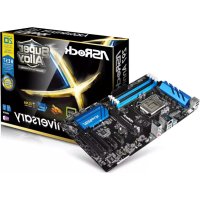
Z97 Anniversary - Motherboard ASROCK - Free user manual and instructions
Find the device manual for free Z97 Anniversary ASROCK in PDF.


| Product type | ATX motherboard |
| Brand | ASRock |
| Model | Z97 Anniversary |
| Processor socket | LGA1150 |
| Chipset | Intel® Z97 |
| Supported memory | DDR3, up to 32 GB, 4 slots, dual channel |
| Max memory frequency | DDR3 3100+ (OC) |
| Expansion slots | 1 x PCIe 3.0 x16, 3 x PCIe 2.0 x1, 2 x PCI |
| Storage | 6 x SATA3 6 Gb/s (RAID 0/1/5/10) |
| Audio | 7.1 CH HD (Realtek ALC887) |
| Network | Gigabit LAN Intel® I218V |
| Rear panel connectivity | 1x PS/2, 1x HDMI, 2x USB 2.0, 4x USB 3.0, 1x RJ-45, 3x audio jacks |
| Internal connectivity | 1x COM, 1x TPM, 6x SATA3, USB 2.0/3.0 headers, front panel audio |
| Required power | ATX 24-pin + 12V 8-pin |
| Form factor | ATX (305 mm x 244 mm) |
| Supported operating systems | Windows 10/8.1/8/7 (32/64 bit) |
| Special features | ASRock BCLK Full-range overclocking, solid capacitors, surge protection |
| Maintenance and cleaning | Use a soft, dry cloth. Avoid liquids. Unplug before cleaning. |
| Safety | Electrostatic discharge: touch a grounded metal object before handling. Do not touch sensitive components. |
| Spare parts and repairability | The motherboard is not user repairable. Spare parts: SATA cables (optional), I/O shield. Contact ASRock support. |
| General information | Warranty: according to applicable legislation. Full manual available online. Website: www.asrock.com |
Frequently Asked Questions - Z97 Anniversary ASROCK
User questions about Z97 Anniversary ASROCK
0 question about this device. Answer the ones you know or ask your own.
Ask a new question about this device
Download the instructions for your Motherboard in PDF format for free! Find your manual Z97 Anniversary - ASROCK and take your electronic device back in hand. On this page are published all the documents necessary for the use of your device. Z97 Anniversary by ASROCK.
USER MANUAL Z97 Anniversary ASROCK
Copyright©2014 ASRock INC. All rights reserved.

Copyright Notice:
No part of this documentation may be reproduced, transcribed, transmitted, or translated in any language, in any form or by any means, except duplication of documentation by the purchaser for backup purpose, without written consent of ASRock Inc.
Products and corporate names appearing in this documentation may or may not be registered trademarks or copyrights of their respective companies, and are used only for identification or explanation and to the owners' benefit, without intent to infringe.
Disclaimer:
Specifications and information contained in this documentation are furnished for informational use only and subject to change without notice, and should not be constructed as a commitment by ASRock. ASRock assumes no responsibility for any errors or omissions that may appear in this documentation.
With respect to the contents of this documentation, ASRock does not provide warranty of any kind, either expressed or implied, including but not limited to the implied warranties or conditions of merchantability or fitness for a particular purpose.
In no event shall ASRock, its directors, officers, employees, or agents be liable for any indirect, special, incidental, or consequential damages (including damages for loss of profits, loss of business, loss of data, interruption of business and the like), even if ASRock has been advised of the possibility of such damages arising from any defect or error in the documentation or product.

This device complies with Part 15 of the FCC Rules. Operation is subject to the following two conditions:
(1) this device may not cause harmful interference, and
(2) this device must accept any interference received, including interference that may cause undesired operation.
CALIFORNIA, USA ONLY
The Lithium battery adopted on this motherboard contains Perchlorate, a toxic substance controlled in Perchlorate Best Management Practices (BMP) regulations passed by the California Legislature. When you discard the Lithium battery in California, USA, please follow the related regulations in advance.
"Perchlorate Material-special handling may apply, see www.dtsc.ca.gov/hazardouswaste/perchlorate"
ASRock Website: http://www.asrock.com
The terms HDMI ^™ and HDMI High-Definition Multimedia Interface, and the HDMI logo are trademarks or registered trademarks of HDMI Licensing LLC in the United States and other countries.

HIGH-DEFINITION MULTIMEDIA INTERFACE
Motherboard Layout
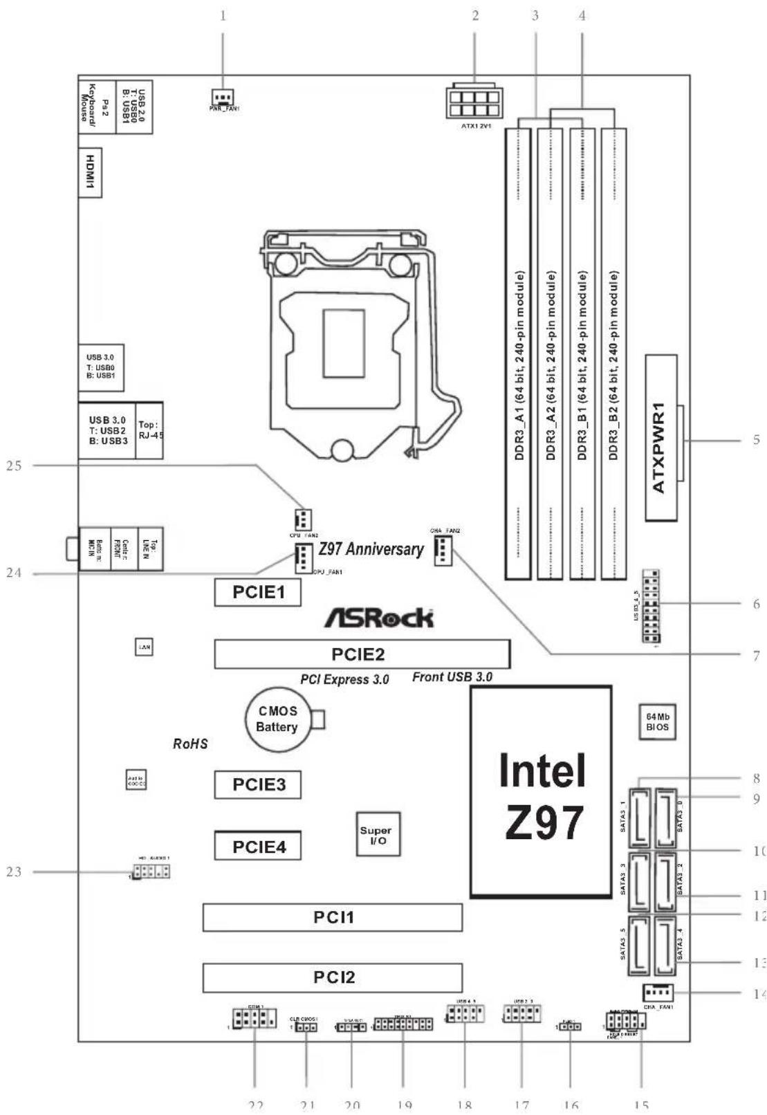
No. Description
1 Power Fan Connector (PWR_FAN1)
2 ATX 12V Power Connector (ATX12V1)
3 2 x 240-pin DDR3 DIMM Slots (DDR3_A1, DDR3_B1)
4 2 x 240-pin DDR3 DIMM Slots (DDR3_A2, DDR3_B2)
5 ATX Power Connector (ATXPWR1)
6 USB 3.0 Header (USB3_4_5)
7 Chassis Fan Connector (CHA_FAN2)
8 SATA3 Connector (SATA3_1)
9 SATA3 Connector (SATA3_0)
10 SATA3 Connector (SATA3_3)
11 SATA3 Connector (SATA3_2)
12 SATA3 Connector (SATA3_5)
13 SATA3 Connector (SATA3_4)
14 Chassis Fan Connector (CHA_FAN1)
15 System Panel Header (PANEL1)
16 Power LED Header (PLED1)
17 USB 2.0 Header (USB2_3)
18 USB 2.0 Header (USB4_5)
19 TPM Header (TPMS1)
20 Chassis Speaker Header (SPEAKER1)
21 Clear CMOS Jumper (CLRCMOS1)
22 COM Port Header (COM1)
23 Front Panel Audio Header (HD_AUDIO1)
24 CPU Fan Connector (CPU_FAN1)
25 CPU Fan Connector (CPU_FAN2)
I/O Panel
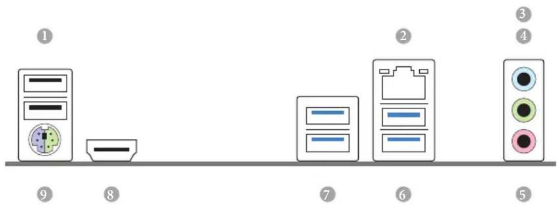
| No. | Description No. | Description | |
| 1 | USB 2.0 Ports (USB01) | 6 | USB 3.0 Ports (USB3_23) |
| 2 | LAN RJ-45 Port* | 7 | USB 3.0 Ports (USB3_01) |
| 3 | Line In (Light Blue) | 8 | HDMI Port |
| 4 | Front Speaker (Lime) | 9 | PS/2 Mouse/Keyboard Port |
| 5 | Microphone (Pink) |
* There are two LEDs on each LAN port. Please refer to the table below for the LAN port LED indications.
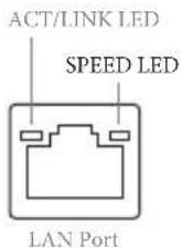
| Activity / Link LED Speed LED | |||
| Status Description Status Description | |||
| Off No Link Off | 10Mbps connection | ||
| Blinking Data Activity Orange 100Mbps connection | |||
| On Link Green 1Gbps connection | |||
Chapter 1 Introduction
Thank you for purchasing ASRock Z97 Anniversary motherboard, a reliable motherboard produced under ASRock's consistently stringent quality control. It delivers excellent performance with robust design conforming to ASRock's commitment to quality and endurance.

Because the motherboard specifications and the BIOS software might be updated, the content of this manual will be subject to change without notice. In case any modifications of this manual occur, the updated version will be available on ASRock's website without further notice. If you require technical support related to this motherboard, please visit our website for specific information about the model you are using. You may find the latest VGA cards and CPU support list on ASRock's website as well. ASRock website http://www.asrock.com.
1.1 Package Contents
• ASRock Z97 Anniversary Motherboard (ATX Form Factor)
• ASRock Z97 Anniversary Quick Installation Guide
• ASRock Z97 Anniversary Support CD
• 2 x Serial ATA (SATA) Data Cables (Optional)
• 1 x I/O Panel Shield
1.2 Specifications
Platform
- ATX Form Factor
- Solid Capacitor design
• High Density Glass Fabric PCB
CPU
- Supports 5^th Generation Intel® CoreTM i7/i5/i3/Pentium®/Celeron® Processors (Socket 1150)
- Supports New 4 ^th and 4 ^th Generation Intel ^ Xeon ^ /Core ^TM i7/i5/i3/Pentium ^ /Celeron ^ Processors (Socket 1150)
- Digi Power design
• 4 Power Phase design
• Supports Intel® Turbo Boost 2.0 Technology
• Supports Intel® K-Series unlocked CPUs
• Supports ASRock BCLK Full-range Overclocking
Chipset
- Intel® Z97
Memory
• Dual Channel DDR3 Memory Technology
• 4 x DDR3 DIMM Slots
- Supports DDR3 3100+(OC)/2933(OC)/2800(OC)/2400(OC)/2133(OC)/1866(OC)/1600/1333/1066 non-ECC, un-buffered memory
• Max. capacity of system memory: 32GB (see CAUTION)
- Supports Intel® Extreme Memory Profile (XMP) 1.3 / 1.2
Expansion
• 1 x PCI Express 3.0 x16 Slot (PCIE2: x16 mode)
• 3 x PCI Express 2.0 x1 Slots
- 2 x PCI Slots
Graphics
- Intel® HD Graphics Built-in Visuals and the VGA outputs can be supported only with processors which are GPU integrated.
- Supports Intel® HD Graphics Built-in Visuals : Intel® Quick Sync Video with AVC, MVC (S3D) and MPEG-2 Full HW Encode1, Intel® InTru™ 3D, Intel® Clear Video HD Technology, Intel® Insider™, Intel® HD Graphics 4400/4600
-
Pixel Shader 5.0, DirectX 11.1
• Max. shared memory 1792MB -
Supports HDMI with max. resolution up to 1920x1200 @ 60Hz
- Supports Auto Lip Sync, Deep Color (12bpc), xvYCC and HBR (High Bit Rate Audio) with HDMI Port (Compliant HDMI monitor is required)
• Supports HDCP with HDMI Port - Supports Full HD 1080p Blu-ray (BD) playback with HDMI Port
Audio
• 7.1 CH HD Audio (Realtek ALC887 Audio Codec)
* To configure 7.1 CH audio, please use an HD front panel audio module and enable the multi-channel audio feature through the audio driver.
• Supports Surge Protection (ASRock Full Spike Protection)
- ELNA Audio Caps
LAN
• Gigabit LAN 10/100/1000 Mb/s
• Giga PHY Intel ^® I218V
• Supports Intel® Remote Wake Technology
• Supports Wake-On-LAN
- Supports Lightning/ESD Protection (ASRock Full Spike Protection)
• Supports Energy Efficient Ethernet 802.3az
- Supports PXE
Rear Panel I/O
• 1 x PS/2 Mouse/Keyboard Port
- 1 x HDMI Port
- 2 x USB 2.0 Ports (Supports ESD Protection (ASRock Full Spike Protection))
- 4 x USB 3.0 Ports (Supports ESD Protection (ASRock Full Spike Protection))
- 1 x RJ-45 LAN Port with LED (ACT/LINK LED and SPEED LED)
• HD Audio Jacks: Line in / Front Speaker / Microphone
Storage
- 6 x SATA3 6.0 Gb/s Connectors, support RAID (RAID 0, RAID 1, RAID 5, RAID 10, Intel Rapid Storage Technology 13 and Intel Smart Response Technology), NCQ, AHCI and Hot Plug
Connector
• 1 x COM Port Header
- 1 x TPM Header
• 1 x Power LED Header
- 2 x CPU Fan Connectors (1 x 4-pin, 1 x 3-pin)
• 2 x Chassis Fan Connectors (2 x 4-pin)
• 1 x Power Fan Connector (3-pin)
• 1 x 24 pin ATX Power Connector
• 1 x 8 pin 12V Power Connector
• 1 x Front Panel Audio Connector
- 2 x USB 2.0 Headers (Support 4 USB 2.0 ports) (Supports ESD Protection (ASRock Full Spike Protection))
- 1 x USB 3.0 Header (Supports 2 USB 3.0 ports) (Supports ESD Protection (ASRock Full Spike Protection))
BIOS
Feature
- 64Mb AMI UEFI Legal BIOS with multilingual GUI support
• ACPI 1.1 Compliant wake up events - SMBIOS 2.3.1 support
• CPU, DRAM, PCH 1.05V Voltage multi-adjustment
Hardware
Monitor
• CPU/Chassis temperature sensing
• CPU/Chassis/Power Fan Tachometer
- CPU/Chassis Quiet Fan (Auto adjust chassis fan speed by CPU temperature)
• CPU/Chassis Fan multi-speed control
• Voltage monitoring: +12V, +5V, +3.3V, CPU Vcore
OS
- Microsoft® Windows® 10 64-bit / 8.1 32-bit / 8.1 64-bit / 8 32-bit / 8 64-bit / 7 32-bit / 7 64-bit
Certifica-
tions
- FCC, CE, WHQL
- ErP/EuP ready (ErP/EuP ready power supply is required)

Please realize that there is a certain risk involved with overclocking, including adjusting the setting in the BIOS, applying Untied Overclocking Technology, or using third-party overclocking tools. Overclocking may affect your system's stability, or even cause damage to the components and devices of your system. It should be done at your own risk and expense. We are not responsible for possible damage caused by overclocking.

Due to limitation, the actual memory size may be less than 4GB for the reservation for system usage under Windows ^® 32-bit operating systems. Windows ^® 64-bit operating systems do not have such limitations. You can use ASRock XFast RAM to utilize the memory that Windows ^® cannot use.
Chapter 2 Installation
This is an ATX form factor motherboard. Before you install the motherboard, study the configuration of your chassis to ensure that the motherboard fits into it.
Pre-installation Precautions
Take note of the following precautions before you install motherboard components or change any motherboard settings.
- Make sure to unplug the power cord before installing or removing the motherboard components. Failure to do so may cause physical injuries and damages to motherboard components.
- In order to avoid damage from static electricity to the motherboard's components, NEVER place your motherboard directly on a carpet. Also remember to use a grounded wrist strap or touch a safety grounded object before you handle the components.
- Hold components by the edges and do not touch the ICs.
- Whenever you uninstall any components, place them on a grounded anti-static pad or in the bag that comes with the components.
- When placing screws to secure the motherboard to the chassis, please do not over-tighten the screws! Doing so may damage the motherboard.
2.1 Installing the CPU

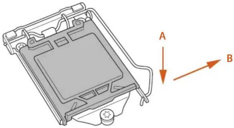
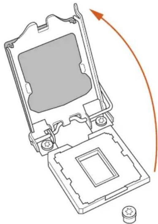
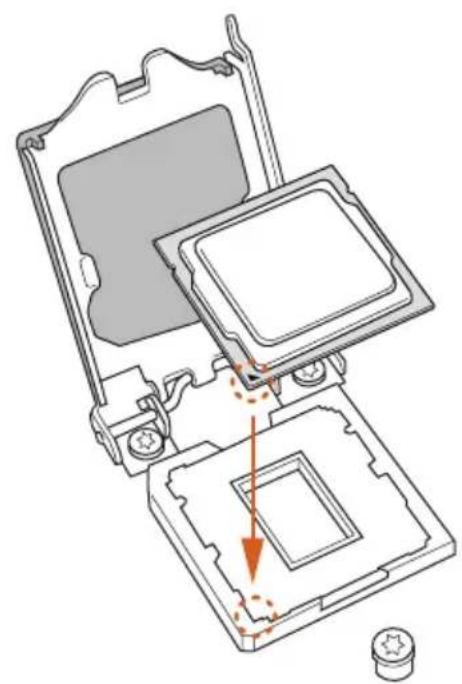
- Before you insert the 1150-Pin CPU into the socket, please check if the PnP cap is on the socket, if the CPU surface is unclean, or if there are any bent pins in the socket. Do not force to insert the CPU into the socket if above situation is found. Otherwise, the CPU will be seriously damaged.
- Unplug all power cables before installing the CPU.
1
natural_image
Technical line drawing of a mechanical component with labeled directional arrows (A and B) indicating movement or force directions.2
natural_image
Technical line drawing of a mechanical device with internal components and an orange curved arrow indicating rotation (no text or symbols)3
natural_image
Technical diagram of a computer processor internal structure showing mounting holes and a highlighted slot (no text or symbols)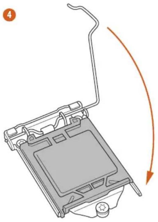
natural_image
Diagram of a computer monitor chassis with an orange curved arrow indicating motion (no text or symbols)5
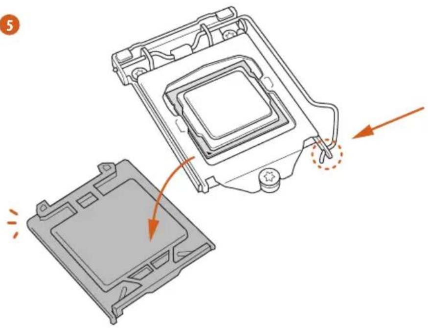

Please save and replace the cover if the processor is removed. The cover must be placed if you wish to return the motherboard for after service.
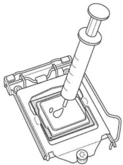
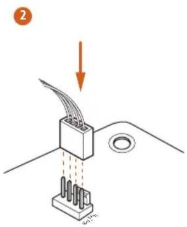
2.2 Installing the CPU Fan and Heatsink
natural_image
Line drawing of a mechanical device with a pipette inserted into a square base (no text or symbols)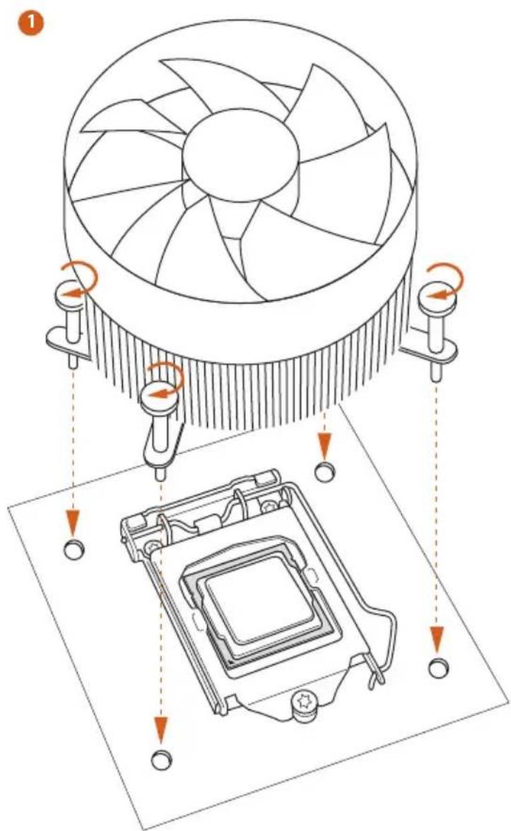
2.3 Installing Memory Modules (DIMM)
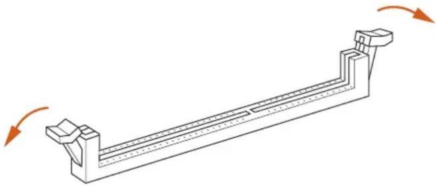
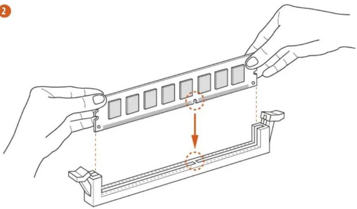
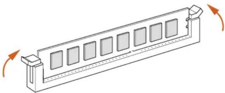
This motherboard provides four 240-pin DDR3 (Double Data Rate 3) DIMM slots, and supports Dual Channel Memory Technology.

- For dual channel configuration, you always need to install identical (the same brand, speed, size and chip-type) DDR3 DIMM pairs.
- It is unable to activate Dual Channel Memory Technology with only one or three memory module installed.
- It is not allowed to install a DDR or DDR2 memory module into a DDR3 slot; otherwise, this motherboard and DIMM may be damaged.
Dual Channel Memory Configuration
Priority DDR3_A1 DDR3_A2 DDR3_B1 DDR3_B2
| 1 Populated Populated | |||
| 2 Populated Populated | |||
| 3 Populated Populated Populated Populated |

The DIMM only fits in one correct orientation. It will cause permanent damage to the motherboard and the DIMM if you force the DIMM into the slot at incorrect orientation.
1
natural_image
Technical line drawing of a mechanical support structure with rotational arrows indicating motion (no text or symbols)2
natural_image
Illustration of hands assembling a mechanical component with a highlighted section (no text or symbols)3
natural_image
Isometric line drawing of a rectangular electronic component with multiple square slots and directional arrows indicating rotation (no text or symbols)2.4 Expansion Slots (PCI and PCI Express Slots)
There are 2 PCI slots and 4 PCI Express slots on the motherboard.

Before installing an expansion card, please make sure that the power supply is switched off or the power cord is unplugged. Please read the documentation of the expansion card and make necessary hardware settings for the card before you start the installation.
PCI slots:
The PCI1 and PCI2 slots are used to install expansion cards that have 32-bit PCI interface.
PCIe slots:
PCIE1 (PCIe 2.0 x1 slot) is used for PCI Express x1 lane width cards.
PCIE2 (PCIe 3.0 x16 slot) is used for PCI Express x16 lane width graphics cards.
PCIE3 (PCIe 2.0 x1 slot) is used for PCI Express x1 lane width cards.
PCIE4 (PCIe 2.0 x1 slot) is used for PCI Express x1 lane width cards.
2.5 Jumpers Setup
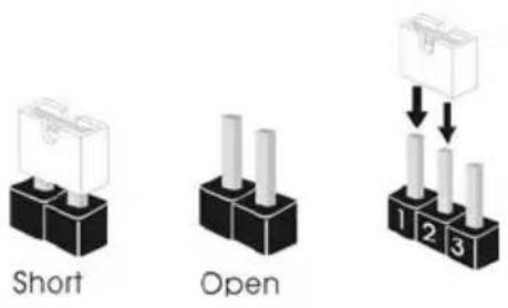
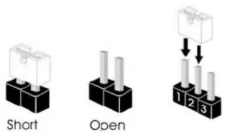
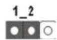
The illustration shows how jumpers are setup. When the jumper cap is placed on the pins, the jumper is "Short". If no jumper cap is placed on the pins, the jumper is "Open". The illustration shows a 3-pin jumper whose pin1 and pin2 are "Short" when a jumper cap is placed on these 2 pins.
Clear CMOS Jumper (CLRCMOS1)
(see p.1, No. 21)
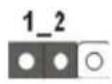
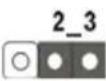
Clear CMOSDefault
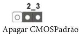
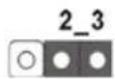
CLRCMOS1 allows you to clear the data in CMOS. To clear and reset the system parameters to default setup, please turn off the computer and unplug the power cord from the power supply. After waiting for 15 seconds, use a jumper cap to short pin2 and pin3 on CLRCMOS1 for 5 seconds. However, please do not clear the CMOS right after you update the BIOS. If you need to clear the CMOS when you just finish updating the BIOS, you must boot up the system first, and then shut it down before you do the clear-CMOS action. Please be noted that the password, date, time, and user default profile will be cleared only if the CMOS battery is removed.
2.6 Onboard Headers and Connectors

Onboard headers and connectors are NOT jumpers. Do NOT place jumper caps over these headers and connectors. Placing jumper caps over the headers and connectors will cause permanent damage to the motherboard.
System Panel Header (9-pin PANEL1) (see p.1, No. 15)
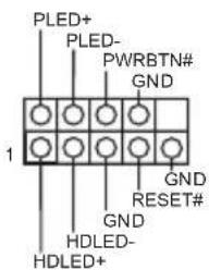
Connect the power switch, reset switch and system status indicator on the chassis to this header according to the pin assignments below. Note the positive and negative pins before connecting the cables.

PWRBTN (Power Switch):
Connect to the power switch on the chassis front panel. You may configure the way to turn off your system using the power switch.
RESET (Reset Switch):
Connect to the reset switch on the chassis front panel. Press the reset switch to restart the computer if the computer freezes and fails to perform a normal restart.
PLED (System Power LED):
Connect to the power status indicator on the chassis front panel. The LED is on when the system is operating. The LED keeps blinking when the system is in S1/S3 sleep state. The LED is off when the system is in S4 sleep state or powered off (S5).
HDLED (Hard Drive Activity LED):
Connect to the hard drive activity LED on the chassis front panel. The LED is on when the hard drive is reading or writing data.
The front panel design may differ by chassis. A front panel module mainly consists of power switch, reset switch, power LED, hard drive activity LED, speaker and etc. When connecting your chassis front panel module to this header, make sure the wire assignments and the pin assignments are matched correctly.
Power LED Header
(3-pin PLED1)
(see p.1, No. 16)
Serial ATA3 Connectors
(SATA3_0:
see p.1, No. 9)
(SATA3_1:
see p.1, No. 8)
(SATA3_2:
see p.1, No. 11)
(SATA3_3:
see p.1, No. 10)
(SATA3_4:
see p.1, No. 13)
(SATA3_5:
see p.1, No. 12)
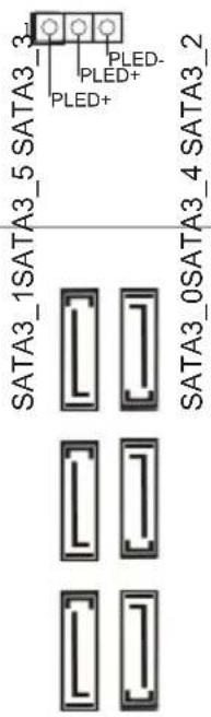
Please connect the chassis power LED to this header to indicate the system's power status.
These six SATA3
connectors support SATA data cables for internal storage devices with up to 6.0 Gb/s data transfer rate.
USB 2.0 Headers
(9-pin USB2_3)
(see p.1, No. 17)
(9-pin USB4_5)
(see p.1, No. 18)
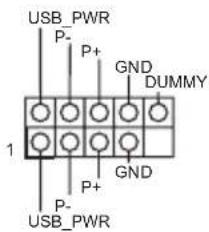
Besides two USB 2.0 ports on the I/O panel, there are two headers on this motherboard. Each USB 2.0 header can support two ports.
USB 3.0 Header
(19-pin USB3_4_5)
(see p.1, No. 6)
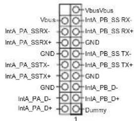
Besides four USB 3.0 ports on the I/O panel, there is one header on this motherboard. Each USB 3.0 header can support two ports.
Front Panel Audio Header
(9-pin HD_AUDIO1)
(see p.1, No. 23)
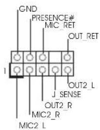
This header is for
connecting audio devices to the front audio panel.

- High Definition Audio supports Jack Sensing, but the panel wire on the chassis must support HDA to function correctly. Please follow the instructions in our manual and chassis manual to install your system.
- If you use an AC'97 audio panel, please install it to the front panel audio header by the steps below:
A. Connect Mic_IN (MIC) to MIC2_I.
B. Connect Audio_R (RIN) to OUT2_R and Audio_L (LIN) to OUT2_L.
C. Connect Ground (GND) to Ground (GND).
D. MIC_RET and OUT_RET are for the HD audio panel only. You don't need to connect them for the AC'97 audio panel.
E. To activate the front mic, go to the "FrontMic" Tab in the Realtek Control panel and adjust "Recording Volume".
Chassis Speaker Header
(4-pin SPEAKER1)
(see p.1, No. 20)
DUMMY SPEAKER
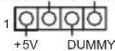
Please connect the chassis speaker to this header.
Chassis and Power Fan
Connectors
(4-pin CHA_FAN1)
(see p.1, No. 14)
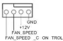
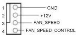
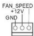
Please connect fan cables to the fan connectors and match the black wire to the ground pin.
(4-pin CHA_FAN2)
(see p.1, No. 7)
(3-pin PWR_FAN1)
(see p.1, No. 1)
CPU Fan Connectors
(4-pin CPU_FAN1)
(see p.1, No. 24)

This motherboard provides a 4-Pin CPU fan
(Quiet Fan) connector. If you plan to connect a
3-Pin CPU fan, please connect it to Pin 1-3.
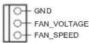
(3-pin CPU_FAN2)
(see p.1, No. 25)
ATX Power Connector (24-pin ATXPWR1) (see p.1, No. 5)
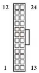
This motherboard provides a 24-pin ATX power connector. To use a 20-pin ATX power supply, please plug it along Pin 1 and Pin 13.
ATX 12V Power Connector (8-pin ATX12V1) (see p.1, No. 2)
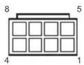
This motherboard provides an 8-pin ATX 12V power connector. To use a 4-pin ATX power supply, please plug it along Pin 1 and Pin 5.
Serial Port Header (9-pin COM1) (see p.1, No. 22)
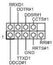
This COM1 header supports a serial port module.
TPM Header (17-pin TPMS1) (see p.1, No. 19)
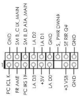
This connector supports Trusted Platform Module (TPM) system, which can securely store keys, digital certificates, passwords, and data. A TPM system also helps enhance network security, protects digital identities, and ensures platform integrity.
1 Einleitung
Serial-ATA-III-Anschlüsse
(SATA3_0:
siehe S. 1, Nr. 9)
(SATA3_1:
siehe S. 1, Nr. 8)
(SATA3_2:
siehe S. 1, Nr. 11)
(SATA3_3:
siehe S. 1, Nr. 10)
(SATA3_4:
siehe S. 1, Nr. 13)
(SATA3_5:
siehe S. 1, Nr. 12)
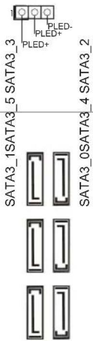
- 6 x Connettori SATA3 6,0 Gb/s, supportano RAID (RAID 0, RAID 1, RAID 5, RAID 10, Intel Rapid Storage Technology 13 e Intel Smart Response Technology), NCQ, AHCI e Hot Plug
Connet- tore
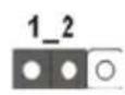
Apagar o Jumper CMOS (CLRCMOS1) (ver p.1, N.° 21)
- 6 x SATA3 6,0 Gb/s Bağlayıcısı, RAID (RAID 0, RAID 1, RAID 5, RAID 10, Intel Rapid Storage Technology 13 ve Intel Smart Response Technology), NCQ, AHCI ve Tak Çıkar destekler
Bağlayıcı
Clear CMOS 점퍼
(CLRCMOS1)
TPM(Trusted Platform
Module) 시스템을 지원
합니다 .TPM 시스템
은 네트워크 보안을 강
화하고,디지털 신원을
보호하며 플랫폼 무결
성을 유지합니다.

natural_image
Simple graphic with a magnifying glass icon and a horizontal line, no text or symbols present.1.1 パッケージの内容
1.2 仕様
CPU
TM
^TM i7/i5/i3/
TM
TM
natural_image
Blank white image with no visible content, text, or symbols日本語
LAN
I/O
os
/ 8 64-bit / 7 32-bit / 7 64-bit


1.3 ジャンパー設定
(CLRCMOS1)
8 64-bit / 7 32-bit / 7 64-bit
认证
清除 CMOS 跳线 (CLRCMOS1)
(见第 1 页,第 21 个)
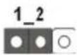
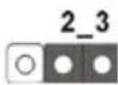
清除 CMOS默认
清除 CMOS 跳線
(CLRCMOS1)
(請參閱第1頁,編號21)
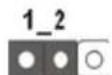
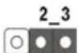
清除 CMOS預設
If you need to contact ASRock or want to know more about ASRock, you're welcome to visit ASRock's website at http://www.asrock.com; or you may contact your dealer for further information. For technical questions, please submit a support request form at http://www.asrock.com/support/tsd.asp
ASRock Incorporation
2F., No.37, Sec. 2, Jhongyang S. Rd., Beitou District,
Taipei City 112, Taiwan (R.O.C.)
ASRock EUROPE B.V.
Bijsterhuizen 3151
6604 LV Wijchen
The Netherlands
Phone: +31-24-345-44-33
Fax: +31-24-345-44-38
ASRock America, Inc.
13848 Magnolia Ave, Chino, CA91710
U.S.A.
Phone: +1-909-590-8308
Fax: +1-909-590-1026
For the following equipment:
Motherboard
(Product Name)
Z97 Anniversary / ASRock
(Model Designation / Trade Name)
ASRock Incorporation
(Manufacturer Name)
2F., No.37, Sec. 2, Jhongyang S. Rd., Beitou District, Taipei City 112, Taiwan (R.O.C.)
(Manufacturer Address)
is herewith confirmed to comply with the requirements set out in the Council Directive on the Approximation of the Laws of the Member States relating to Electromagnetic Compatibility Directive (2004/108/EC) and Safety Directive (2006/95/EC), the following standards are applied:
EN 55022: 2006+A1:2007
EN 61000-3-2: 2009
EN 61000-3-3: 2008
EN 55024: 1998 + A1:2001 + A2:2003
IEC 61000-4-2: 2008;
IEC 61000-4-3: 2010; IEC 61000-4-4: 2010;
IEC 61000-4-5: 2005; IEC 61000-4-6: 2008;
IEC 61000-4-8: 2009; IEC 61000-4-11: 2004;
EN 60950-1:2005 + A1:2009
IEC 60950-1:2006 + A11:2009 + A1:2010 + A12:2011
The following manufacturer / importer or authorized representative established within the EUT is responsible for this declaration:
ASRock EUROPE B.V.
(Company Name)
Bijsterhuizen 3151 6604 LV Wijchen The Netherlands
(Company Address)
Person responsible for making this declaration:
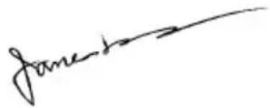
(Name, Surname)
A.V.P
(Position / Title)
June 20, 2014
(Date)
- Copyright Notice:
- Disclaimer:
- CALIFORNIA, USA ONLY
- No. Description
- I/O Panel
- Chapter 1 Introduction
- Package Contents
- Specifications
- Platform
- CPU
- Chipset
- Memory
- Expansion
- Graphics
- Audio
- LAN
- Rear Panel I/O
- Storage
- Connector
- BIOS
- Feature
- Hardware
- Monitor
- OS
- Certifica-
- tions
- Chapter 2 Installation
- Pre-installation Precautions
- Installing the CPU
- Installing the CPU Fan and Heatsink
- Installing Memory Modules (DIMM)
- Dual Channel Memory Configuration
- Expansion Slots (PCI and PCI Express Slots)
- PCI slots:
- PCIe slots:
- Jumpers Setup
- Onboard Headers and Connectors
- PWRBTN (Power Switch):
- RESET (Reset Switch):
- PLED (System Power LED):
- HDLED (Hard Drive Activity LED):
- Einleitung
- Connet- tore
- Bağlayıcı
- 仕様
- ジャンパー設定
- 认证
- ASRock Incorporation
- ASRock EUROPE B.V.
- ASRock America, Inc.
- Motherboard
- Z97 Anniversary / ASRock
- 2F., No.37, Sec. 2, Jhongyang S. Rd., Beitou District, Taipei City 112, Taiwan (R.O.C.)
- Bijsterhuizen 3151 6604 LV Wijchen The Netherlands
Brand : ASROCK
Model : Z97 Anniversary
Category : Motherboard