
Oliscan A600 - Scanner OLIVETTI - Free user manual and instructions
Find the device manual for free Oliscan A600 OLIVETTI in PDF.

| Product type | Professional document scanner |
| Model | Oliscan A600 |
| Brand | Olivetti |
| Main functions | Duplex scanning, automatic document feeder (ADF), MICR reading (optional), inkjet printing (optional), magnetic stripe reader (optional), infrared detection (optional) |
| Supported document formats | Credit card, A6, B5, A4, legal, letter, passbook, ID card, checks |
| Power supply | 24 Vdc, 2.5 A, external adapter (input 100-240 Vac) |
| Connection interface | USB 2.0, RS232 port (optional), USB HUB port (optional) |
| Input tray capacity | Up to 30 documents |
| Double feed detection | Yes, adjustable sensitivity |
| Dimensions (approx.) | Compact desktop scanner (not specified) |
| Weight (approx.) | Not specified, estimated about 4-6 kg |
| Operating conditions | Temperature 15-35°C, avoid humidity and dust |
| Cleaning | Soft damp cloth (water or alcohol), vacuum for dust, clean rollers with lint-free cloth |
| Safety | Unplug before cleaning, use grounded outlet, avoid electromagnetic fields near scanner |
| Power consumption | ENERGY STAR certified, standby after 2 minutes of inactivity |
| Spare parts / repairability | Replaceable ink cartridge, optional MICR head, cartridge cleaning possible, maintenance by authorized personnel |
| Package contents | Quick guide, power cord, USB cable, adapter, support brackets, input/output trays |
Frequently Asked Questions - Oliscan A600 OLIVETTI
User questions about Oliscan A600 OLIVETTI
0 question about this device. Answer the ones you know or ask your own.
Ask a new question about this device
Download the instructions for your Scanner in PDF format for free! Find your manual Oliscan A600 - OLIVETTI and take your electronic device back in hand. On this page are published all the documents necessary for the use of your device. Oliscan A600 by OLIVETTI.
USER MANUAL Oliscan A600 OLIVETTI
Publication issued by:
Olivetti S.p.A.
Via Jervis, 77 - 10015 Ivrea (Italy)
Copyright © 2013 by Olivetti
All rights reserved

ENERGY STAR is an U.S. registered mark.
The ENERGY STAR program is an energy reduction plan introduced by the United States Environmental Protection Agency in response to environmental issues and for the purpose of advancing the development and utilization of more energy efficient office equipment. More information on Energy Star can be found at www.energystar.gov
The mark affixed to the product certifies that the product meets European Union regulations and quality requirements.

Your attention is drawn to the following actions that could compromise the characteristics of the product:
incorrect electrical supply;
incorrect installation; incorrect or improper use, or, in any case, not in accordance with the warnings given in the User Guide supplied with the product;
Replacement of original components or accessories with others of a type not approved by the manufacturer, or carried out by unauthorized personnel.
To clean the machine, use a vacuum cleaner or soft cloth.
First remove the mains plug from the wall socket.
Do not use alcohol, solvents, or hard brushes.
Do not let water or other liquids get inside the scanner.
Information to the user.
For a Class B digital device or peripheral, the instructions furnished the user shall include the following or similar statement, placed in a prominent location in the text of the manual:
Note: This equipment has been tested and found to comply with the limits for a Class B digital device, pursuant to part 15 of the FCC Rules. These limits are designed to provide reasonable protection against harmful interference in a residential installation. This equipment generates, uses and can radiate radio frequency energy and, if not installed and used in accordance with the instructions, may cause harmful interference to radio communications. However, there is no guarantee that interference will not occur in a particular installation. If this equipment does cause harmful interference to radio or television reception, which can be determined by turning the equipment off and on, the user is encouraged to try to correct the interference by one or more of the following measures:
- Reorient or relocate the receiving antenna.
- Increase the separation between the equipment and receiver.
- Connect the equipment into an outlet on a circuit different from that to which the receiver is connected.
- Consult the dealer or an experienced radio/TV technician for help.
THIS CLASS B DIGITAL APPARATUS MEET ALL REQUIREMENTS OF THE CANADIAN INTERFERENCECAUSING EQUIPMENT REGULATIONS
ICES-003. CET APPAREIL NUMERIQUE DE LA CLASSE B EST CONFORME A LA NORME NMB-003 DU CANADA
CONTENTS
CONTENTS III
PRINCIPAL SAFETY REGULATIONS IV
INTRODUCTION 1
OVERVIEW 1
MODELS 1
PACKAGE CONTENTS 2
REMOVING THE PACKING TAPE 3
FRONT VIEW 4
REAR CONNECTIONS 5
INSTALLING YOUR OLISCAN SCANNER 6
MOUNTING THE SCANNER SUPPORTS 6
INSTALLING DOCUMENT INPUT TRAY 7
CABLE CONNECTIONS 9
USING YOUR OLISCAN SCANNER 10
POWERING ON THE SCANNER 10
DOCUMENT SCANNING OPERATIONS 10
Document feeding 10
Scanning A4, Letter or legal-sized documents 11
11
Scanning Mixed Sized Documents 12
Scanning cards 13
1. Scanning passbooks 13
1. Scanning small-sized documents (e.g. A6 or B5) 14
Scanning multicopy documents 14
CONTROL PANEL 15
ROUTINE MAINTENANCE 16
CLEANING THE SCANNER 16
CLEANING THE CARTRIDGE 17
TROUBLESHOOTING 18
GENERAL OPERATING PROBLEMS 18
- Scanner does not power on 18
No USB connection 18
PAPER JAMS 19
SCANNER OPTIONS 20
REMOVING AND INSTALLING AN INKJET PRINT CARTRIDGE 20
Removing a Used Cartridge 20
Installing a Cartridge 21
MAGNETIC STRIPE (SWIPE) CARD READER 22
- Installation and maintenance operations at the workstation must be carried out by authorised technical personnel only.
- The scanner must be connected to a fully earthed electrical supply compliant with current standards, and the electrical socket must be located nearby and easy to reach.
- Avoid using the equipment in excessively cold or hot environments, or exposed to direct sunlight for long periods, as these conditions may damage the unit (correct operation is guaranteed for temperatures in the range 15^ to 35^ ).
- Do not install the scanner in humid or dusty environments. Excessive condensation or humidity may damage the unit. Avoid the equipment coming into contact with liquids of any kind.
- If the MICR option is installed, do not position the scanner near to the external power unit or alongside the PC monitor or any other potential sources of electromagnetic fields as they could impact negatively on the MICR character recognition functionality.
- When performing cleaning or maintenance operations, disconnect the power unit from the power socket. Use just a damp cloth without any liquids or sprays.
- NEVER insert objects into holes or other openings on the equipment.
- Make sure that the work surface is stable to avoid possible damage to the scanner from it falling over.
- Place the scanner firmly on a flat even surface. Tilted or uneven surfaces may cause mechanical or paper feeding problems.
- When moving the scanner, grip it from the base not from the tray.
- Use this equipment only with the original power unit supplied (24V, 2.5 A). Other power units may be dangerous and cause damage to machine.
- Conserve the scanner box and packaging materials for shipping purposes.
Overview
Thank you for choosing the high performance, colour, auto sheet-feed, image scanner model Oliscan A600.
The Oliscan A600 is the Olivetti duplex (double-sided) colour scanner specially designed for the bank counter: a single device that can capture cheques, identity cards and other documents up to A4/letter size. The Oliscan A600 allows all kinds of documents to be scanned, including rigid and plasticised documents, in formats from credit card size to A4, including ID cards. MICR codelines on cheques can be read either by Optical Character Recognition (OCR) or by an optionally installable magnetic sensor, as well as barcode information. The integrated ADF module automatically feeds documents of different sizes and thicknesses, detecting double feeds.
The Scanner is connected to a PC workstation through a USB2.0 port.
For standard operation, cheques and documents are fed into the unit for scanning under the control of the host computer. If the optional inkjet unit is installed, they are endorsed by the Inkjet printer before scanning. The magnetic codeline on cheques (E13B or CMC7 standard), appearing at the bottom of the document, is captured and sent over the USB cable connection, together with the images of the front and rear faces of the document.
On special request, the MICR codeline can be sent via an RS232 interface to emulate an existing MICR reader unit, so as to provide maximum compatibility with legacy applications.
Models
The scanner is available in various configurations, the versions and their main features are as given below:
- BASE Version: dual side color scanner with feeder.
- MICR Version: BASE Version including MICR head for reading cheque codelines.
- JET Version: BASE Version including Inkjet printer for cheque endorsement and printing registration reference number.
- FULL Version: BASE Version including MICR head, magnetic stripe reader (for badges/magnetic cards), Inkjet printer for cheque endorsement.
- H Version: BASE version with addition of infrared illumination for microhole detection.
- HM Version: H version with MICR head for reading cheque magnetic codelines.
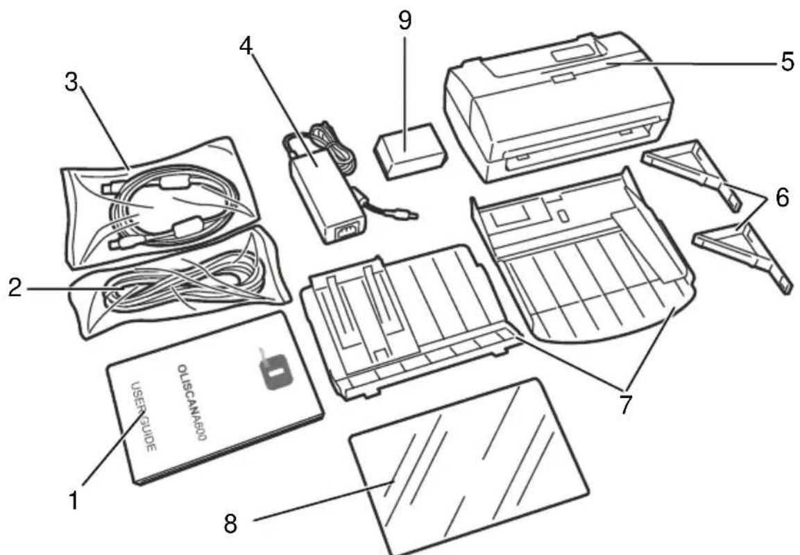
Package contents
The package contains:
- Operator's Quick Guide.
- Power cord.
- USB cable.
- External power unit - Input:100~240VAC, Output: 24VDC.
- Oliscan Main unit.
- Device support brackets - for customer installation (to maximise free desk space available).
- Input and Output trays - for customer installation.
Optional:
Depending on the version of the product ordered, you may also find in the package:
- Transparent holder for scanning mini-documents.
- Inkjet cartridge (optional for both Full and Jet models).
Please unpack attentively, checking the package contents against the checklist. If any items are missing, please contact your dealer immediately. Please keep the packing for future use (sending back for assistance and so on).
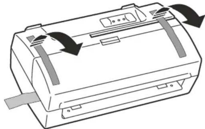
Removing the packing tape
Remove the tape applied to the device during packing operations in order to protect it during transportation.
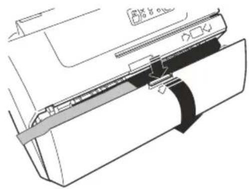
- Remove the two strips of adhesive tape applied to ensure closure of the top cover.
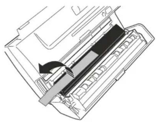
- Open the top cover by pressing down on the locking tab.
- Remove the strip of sponge inside the scanner inserted to protect the glass of the CIS.
Front View
1 2
3
4
5
6
Ref. Description
1 Document Guide
Assists correct alignment of documents in input tray.
2 Input trays
All documents have to be placed correctly at the entrance to the feeder area for scanning single documents, and also manual or automatic feeding of documents into the scanner.
3 Control Panel
On this panel are located 3 LEDs and 2 operator KEYS that are used to control and verify the status and correct operation of the scanner unit.
4 Swipe card (badge) magnetic reader slot (optional)
Insert the badge or card into this slot with the magnetic stripe facing towards the rear of the unit to allow the data to be read.
5 Top Cover
Lift this cover to remove jammed documents or clean the scanning area.
6 Output tray
Documents are automatically stacked in the output tray after scanning.
Rear Connections
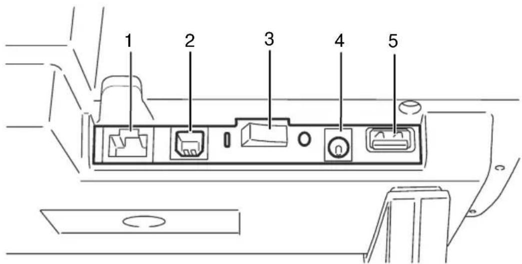
| Connector | Description |
| 1 | RJ connector RS232C port (option)Reserved for special uses (other devices emulation). |
| 2 | USB interface connectorUsed to connect the scanner to the PC. |
| 3 | On/Off SwitchTurns the scanner on and off. |
| 4 | Power socketUsed to connect the power cable to the scanner. |
| 5 | USB HUB host port connector (option)Used to connect other devices to the PC. |
Installing your Oliscan Scanner
NOTE: Refer to the section "Principal safety regulations" on page IV to be sure that you perform the installation correctly and with due regard to safety.
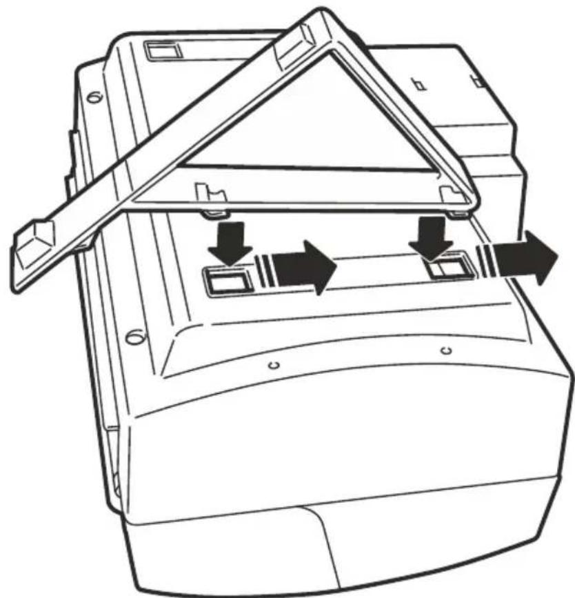
Mounting the scanner supports
The scanner can only be used with a special type of support. Do not use different supports to those supplied by the manufacturer.
- Turn the scanner carefully upside down
- On the underside, towards the Rear connector, insert the two anchoring hooks into the gaps on the bottom, and push the support in the direction indicated by the arrow below, until it locks into place.
- Perform the same operation for the second support.
- Return the unit to its upright position to start operating.
Installing document input tray
WARNING: When the Scanner version includes Inkjet printer, install the inkjet printer cartridge before the input tray installation.
Refer to the "Installing a Cartridge" section on page 21.
- Position the input tray on top of the scanner, aligning it with the scanner input area.
- Insert the lateral anchors of the input tray into the anchoring slots.
- Lower the tray until it rests completely on the Inkjet printer housing, and is inserted into the retaining levers.
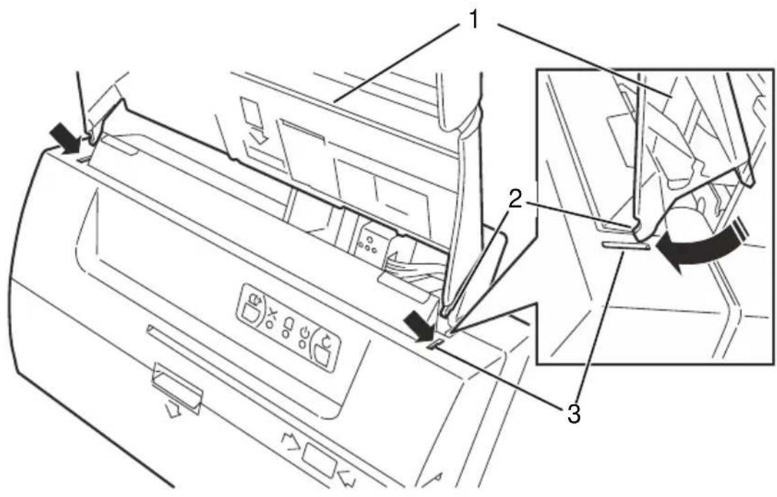
| Ref. | Description |
| 1 | Input tray |
| 2 | Lateral anchors |
| 3 | Anchoring slots |
WARNING: When inserting take maximum care to avoid damaging the lateral anchors.
Make sure that the lateral anchors are fixed well to the anchoring slots
Make sure that the retaining lever is anchored well to lower plastic casing.
- Insert the external anchors into the anchoring slots on the metal plate.
- Insert the chute in a downward direction, then push it up against the scanner to fix it to the two internal anchors under the metal plate.
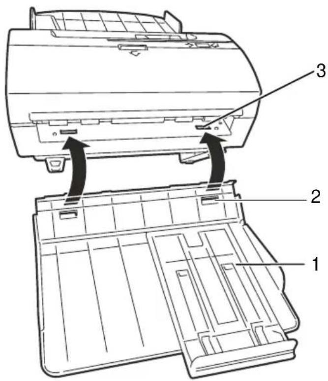
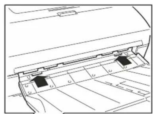
| Ref. | Description |
| 1 | Output tray |
| 2 | External anchors |
| 3 | Anchoring slots |
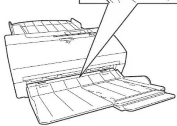
Cable Connections
- Position the scanner near the workstation.
- Connect the external power unit cable to the socket at the rear of the unit.
- Connect the power cable to a mains power supply.
- Use the USB cable to connect the Scanner to the computer.
| Ref. | Description |
| 1 | Power socket |
| 2 | Power cable |
| 3 | Power supply |
| 4 | USB interface connector |
| 5 | USB cable |
| 6 | PC |
WARNING: Do not place the scanner near to the external power supply, alongside the PC monitor or in the vicinity of other electromagnetic fields as they could have an effect on the MICR character recognition rate.
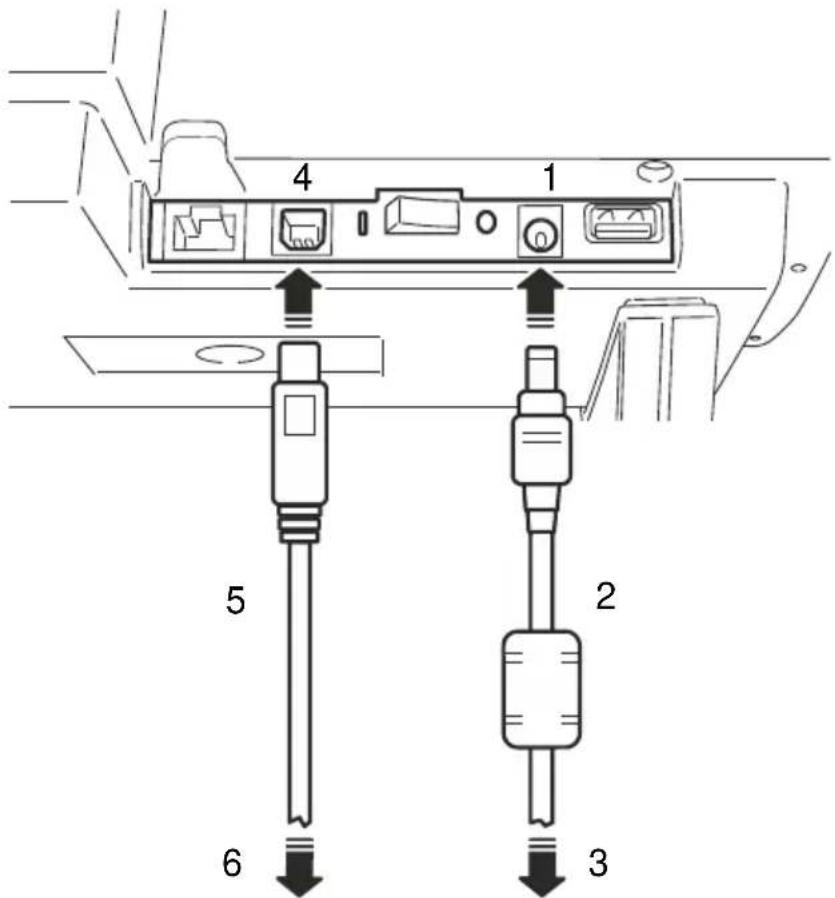
Powering on the scanner
- Press the button located under the input tray on the rear panel of the unit as shown in the figure.
| Ref. | Description |
| 1 | ON/OFF Switch |
Document scanning operations Document feeding
-
Prepare the documents to be scanned by removing all staples, paper clips and pins.
-
Check if documents are glued together. In the case of multicopy documents see paragraph Scanning multicopy documents on page 14.
When a stack of documents is placed in the input tray, documents are fed into the scanner by the auto feeder
30 documents can be placed contemporarily in the input tray. Large-sized documents must be aligned with the right edge. Small-sized documents must be aligned at the centre.
Use the small document guide to improve document feeding. The guide can be moved easily to facilitate operations.
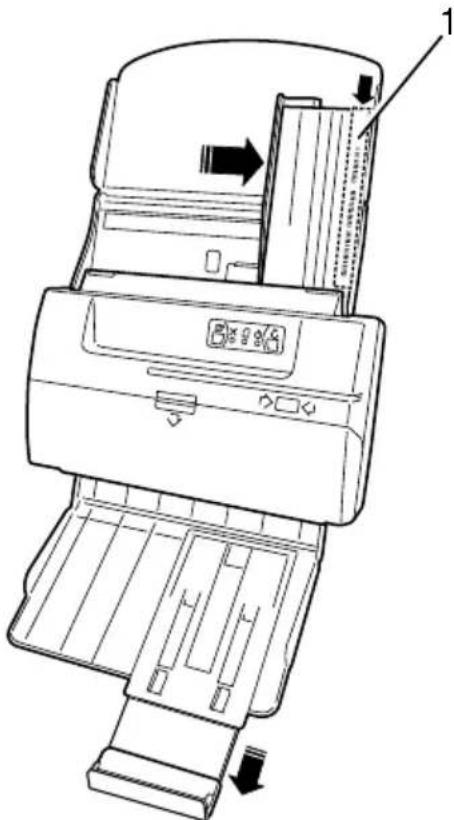
Scanning A4, Letter or legal-sized documents
- If you want to scan A4, letter or legal-sized documents, move the document guide laterally so that the document is pressed gently
between right guide and the document guide.
- Place the document on the input tray upside down (bottom side up, top of document near scanner input area). To scan multi-page documents, insert the stack of documents in reverse order on the tray so that the first page is last (i.e. in contact with the tray, while the last page is visible on top of stack).

Scanning cheques
- Reading using vertical insertion
- Place the cheque on the input tray aligned along the right edge, with the codeline on the right side (1).
- Move the small document guide to improve document feeding.
This insertion direction allows the MICR codeline to be read both optically and by the magnetic sensor when installed.
In this position, inkjet printing is aligned on the right side to obtain the best printing legibility.
- Reading using horizontal insertion
- Place the cheque on the input tray aligned along the right edge, with the codeline at the bottom (1).
When this insertion direction is used, the MICR codeline can be read optically only.
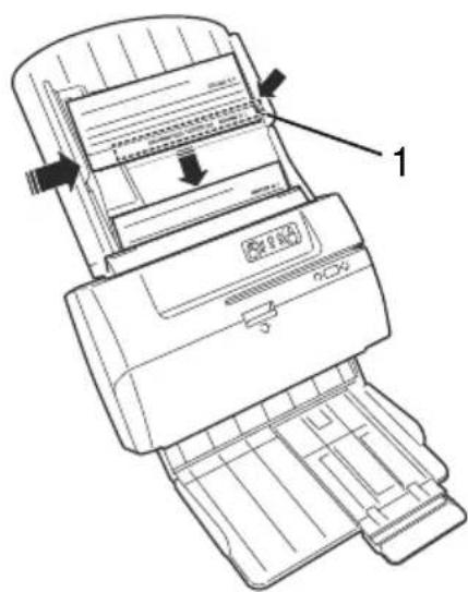
Scanning Mixed Sized Documents
When scanning documents of mixed sizes, alignment or jogging of the documents is decisive:
- Make sure that documents are aligned at the bottom as well as laterally on the right side, to ensure that documents are fed regularly.
- All documents have to be stacked at the feeder entrance in reverse order, with the first page at the back so that it will be the first page fed in (i.e. with first page in contact with the tray and last page visible on top of stack). The auto-feeder can accommodate up to 30 documents. When stacking more than 30 documents, fan out the documents to ensure that feeding occurs in a regular manner.
NOTE: the MICR head for E13B codeline recognition is located on the right side of the scanner. Cheques for processing must be placed with the MICR facing upwards and on the right side of the scanner, as shown in the image above.
When the host sends a Start command to the scanner, documents are scanned on both sides after which the magnetic code line, if present, is recognised and recorded. Documents are then deposited in the output tray, in the same order and position in which they entered the scanner.
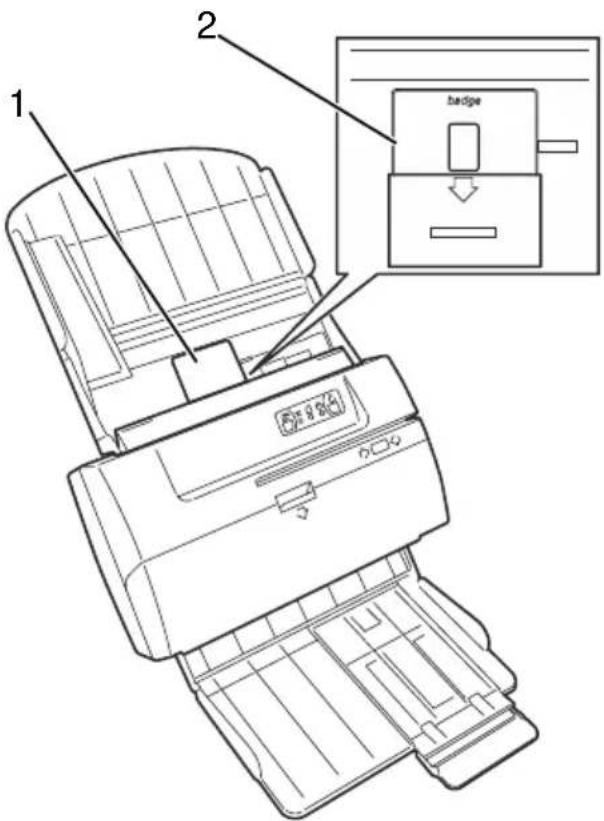
Scanning cards
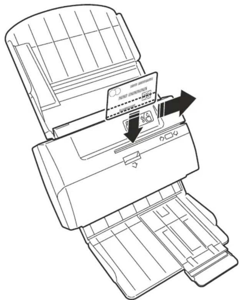
Thick or rigid documents, like identity cards, driver's licenses or envelopes, must be inserted via the central part of the scanner to avoid damaging the MICR read head. These types of documents must be scanned one by one.
- Insert the card (1) into the position indicated by the grooved lines and the arrow icon on the input tray (2).
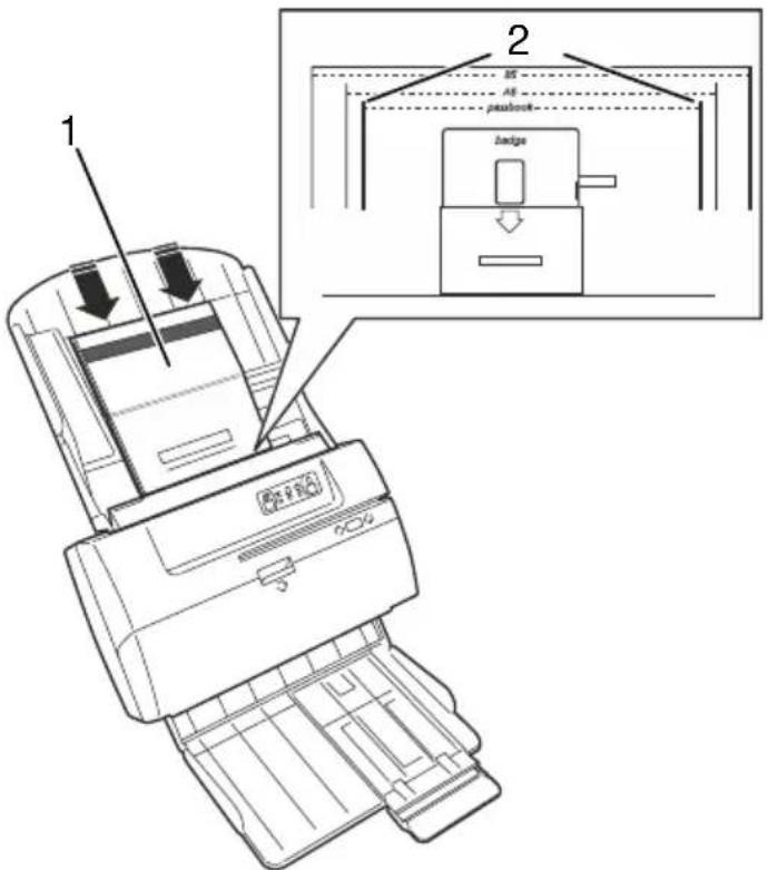
Scanning passbooks
Passbook documents must be inserted at the centre of the input tray to avoid potentially damaging the MICR read head. These types of documents must be scanned one by one.
- Insert the passbook (1) open, with the face against the tray, in the position indicated by the grooved lines and the word "passbook" written on the input tray (2), applying a slight pressure so that the passbook is captured by the automatic feeder mechanism.
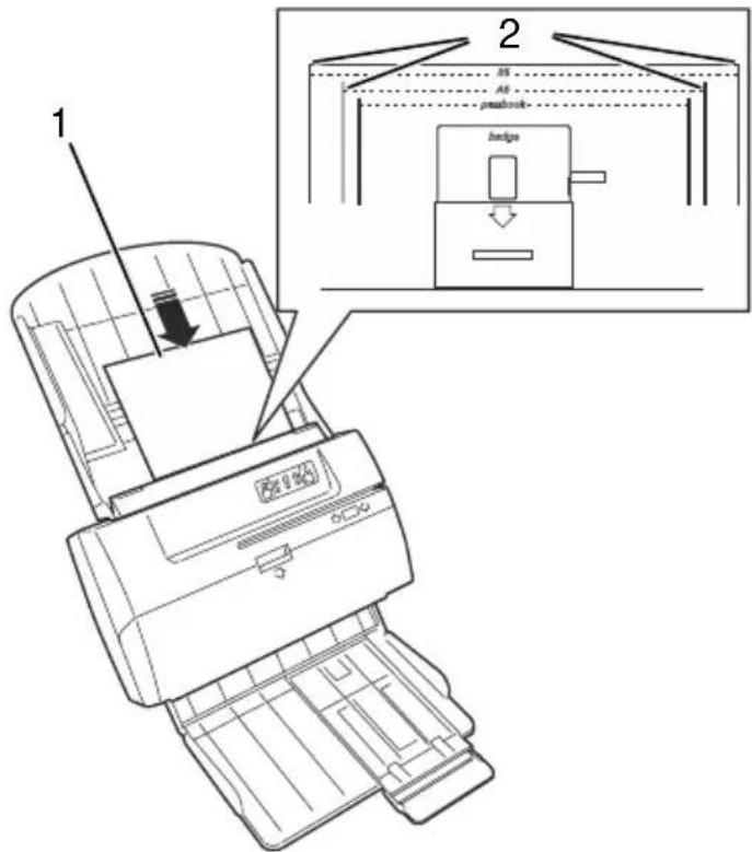
Scanning small-sized documents (e.g. A6 or B5)
Small-sized documents must be inserted at the centre of the input tray, with the longer edge placed horizontally so as to allow better take up by the ADF mechanism.
- Insert the document (1) with the long edge placed horizontally, following the instructions in the section "Scanning A4, letter or legal-sized documents", and in the appropriate position indicated by the grooves and the labels "A6" and "B5" (document format) on the input tray (2).
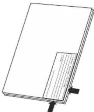
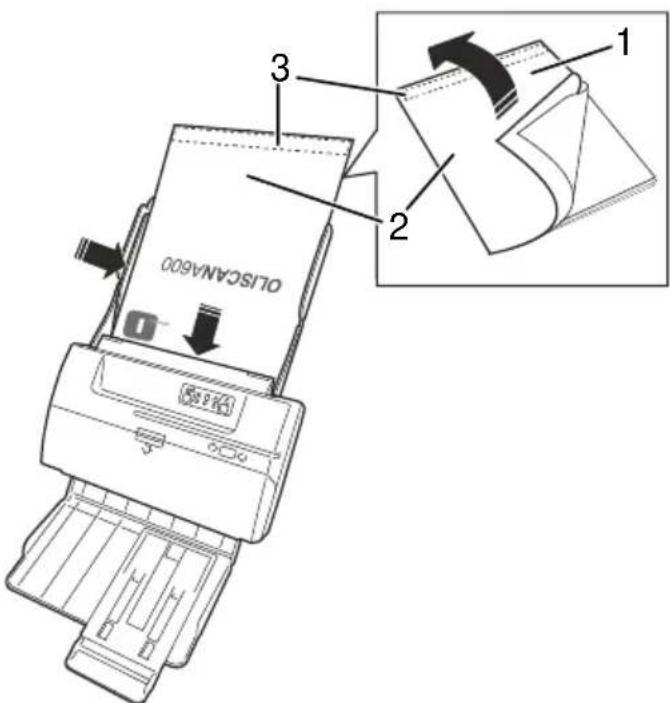
Scanning multicopy documents
Multiple-copy forms (1) can be handled by separating the pages of the form and inserting only one page (2). The page must be inserted with the glued edge (3) at the side or, if inserted vertically, the edge without glue must enter the scanner first.
Double-feed sensor settings
The scanner contains a sensor that checks the thickness of all documents to avoid feeding more than one document at a time. If a double feed occurs, the scanner sends a message to the host computer and the ERROR LED flashes.
If the whole document is thicker than standard paper grammage, then the double-feed control must be disabled. The control (Double Feed Enable) can be found in the Scanner settings dialogue.
If the documents to be scanned are thick, and the double-feed alarm occurs frequently, even when scanning single documents, you can modify the sensitivity of the Thickness photosensor by adjusting the Document feed detection "Threshold" control in the Scanner settings dialogue. The standard adjustment value is around 150. If the alarm occurs for each document capture, then the adjustment value must be increased. On the contrary, if two documents are fed at the same time but the alarm is not activated, then the adjustment value must be decreased.
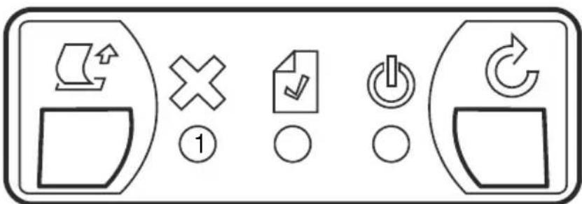
Control Panel
When you switch the unit ON, a self-test checks that the scanner is functioning correctly.
After the configuration procedure is completed, the scanner is ready for use and on the Control Panel the following status information is provided.
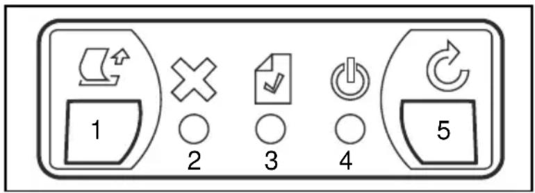
| Ref. | Description | |
| 1 | EJECT KEY Activates the transport motor to eject any jammed document or paper fragment. | |
| 2 | ERROR LED (ORANGE) | |
| ON | Functionality or connection error, scanner offline | |
| Flashing | When feeder LED flashes it signals a double-feed alarm | |
| 3 | FEEDER LED (GREEN) | |
| ON | Document present in the feeder | |
| OFF No documents in the feeder | ||
| 4 | ONLINE LED (BLUE) | |
| ON | Scanner online | |
| Flashing slowly | Scanner is in standby mode | |
| 5 | RESET KEY Reset the error condition due to a unsuccessful insertion operation | |
This chapter describes the simple maintenance operations to be performed periodically to maintain the scanner in good working order.
GeneralWarnings:
Do not use solvents or abrasive substances for cleaning the casing. It is sufficient to use a cloth slightly dampened with alcohol. To remove dust or paper fragments left inside the moving parts, use pressurized air or a soft brush.
Cleaning the Scanner
Scanning documents of different formats and paper types can lead to the accumulation of dust, lint and small particles in the path area between the front and rear scanning heads. Clean this area as described below:
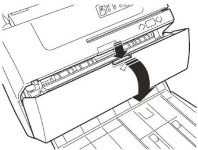
- Lift the top cover by pressing simultaneously on the locking tab.
- Using a lint-free cloth dampened with glass cleaning liquid, clean the glass of the front (1) and back (2) image sensors.
- Close the cover gently.
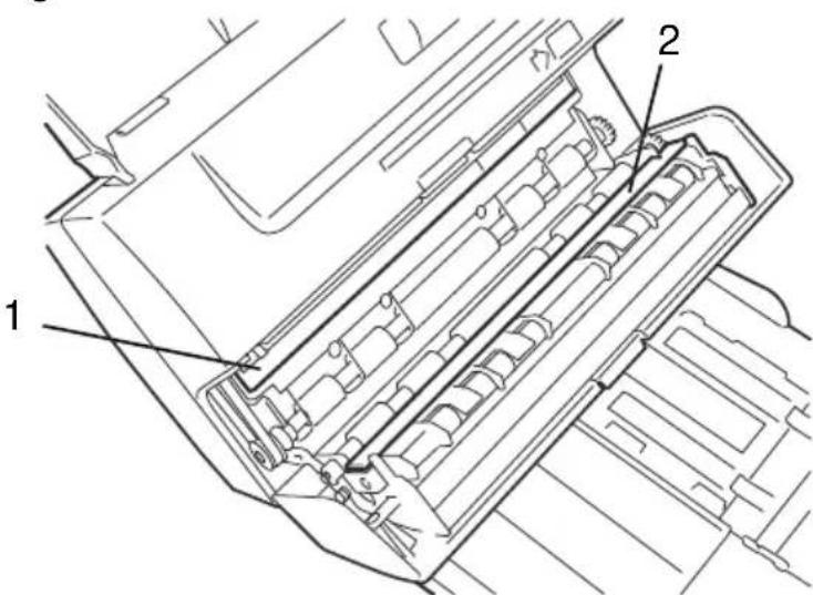
WARNING: Please make sure that no paper or other material remains on the image sensors, as it could cause black lines to appear on images.
To clean the input feeder rollers, use a lint-free cloth dampened with a rubber cleaner of any kind. Follow this procedure:
- Power off the unit and disconnect the USB cable.
- Power on the unit. As the unit is offline, the error LED (on the Control Panel) illuminates with a orange colour light.
- Using the Eject key, start the transport motor with the feeder rollers turning to achieve better cleaning of the roller surface.
Cleaning the Cartridge
When the inkjet printer option is installed, on rare occasions it may be necessary to clean the cartridge printhead, for example, if an ink spill occurs due to a sudden change in atmospheric pressure, printing quality is unsatisfactory or, more importantly, before restarting activity after a long period of disuse. In these circumstances, the printhead contact area must be cleaned by performing the procedures below.
The printhead must NOT be cleaned systematically on a regular basis. Only dabbing movements must be used to clean the printhead, following closely and carefully the steps below:
- Remove the inkjet cartridge as described in the section "Removing a Used Cartridge" on page 20.
- Use a paper towel that does not leave fibres, moistened with water.
- Place the towel on a flat surface, on top of another paper towel folded over several times to create a soft surface.
- Holding the printhead with the nozzles facing downwards, dab it against the paper towel, applying slight downward pressure.
- Maintain contact for a few seconds to allow the excess ink to flow out of the nozzles.
- Move the printhead slowly away from the paper towel, using a vertical movement.
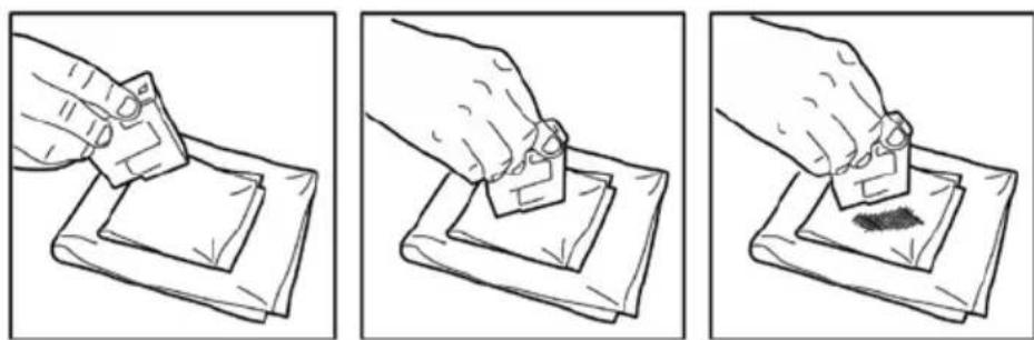
WARNING: Do not rub against the nozzles, or use unmoistened paper, as the nozzles could become clogged.
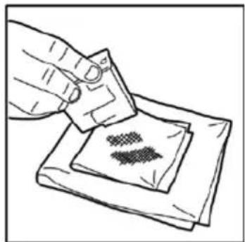
- Repeat the dabbing operation using different parts of the paper towel until the nozzle is clean, and the ink mark left on the paper towel is uniform.
- Reinstall the inkjet cartridge as described in the section "Installing a Cartridge" on page 21.
TROUBLESHOOTING
General operating problems
Scanner does not power on
-
Make sure that the power unit cord is connected correctly to the power socket on the scanner, and that the power unit is connected to the electrical socket, and that the latter is correctly supplied with electricity.
-
Check that the green LED on the power supply is on.
-
Make sure that the power button at the rear of the scanner is in the ON position.
Refer to the section "Powering on the Scanner" on page 10.
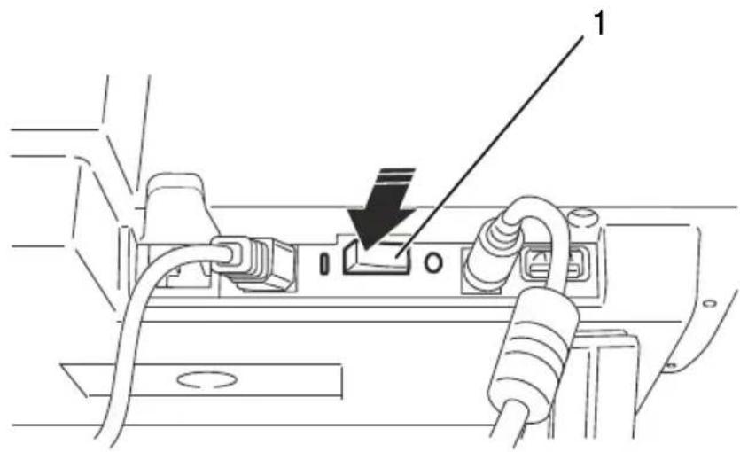
No USB connection
- Check if the orange ERROR LED (1) on the Control Panel is illuminated.
- Make sure that the USB connection cable from the PC is inserted correctly into the USB port socket on the back of the scanner (see the section "Rear Connections" on page 5.
Paper jams
If a paper jam occurs, the paper path must be cleared following this procedure:
- Remove all documents from the input tray.
-
Press the EJECT key (on the Control Panel) to push the jammed document towards the paper output path.
-
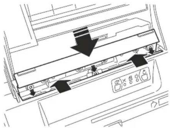
If the document remains jammed and does not move, remove the Automatic Document Feeder (ADF) module, pushing gently upwards on both the side tabs simultaneously.
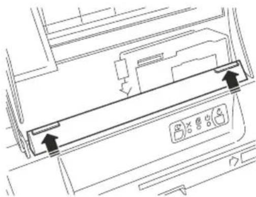
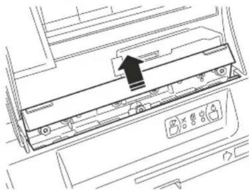
WARNING: During removal operations be very careful not to damage the ADF module.
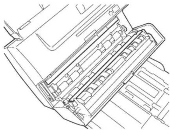
- If the document is jammed in the internal feeding mechanism, lift the top cover.
- Clear the path of any jammed documents and make sure that the rollers are free of paper and other debris.
- Lower the top cover to the correct position and press downwards.
- Reinsert the ADF module, applying a slight pressure to the tray to facilitate the nuts sliding into place.
WARNING: During insertion operations be very careful not to damage the ADF module.
Be sure that the insertion points are well aligned before pushing the module down to the operating position. Be sure that the ADF module is anchored well in place.
NOTE: For safety reasons, the unit is disabled by an interlock switch when the top cover is not correctly positioned.
SCANNER OPTIONS
Removing and Installing an Inkjet Print Cartridge Removing a Used Cartridge
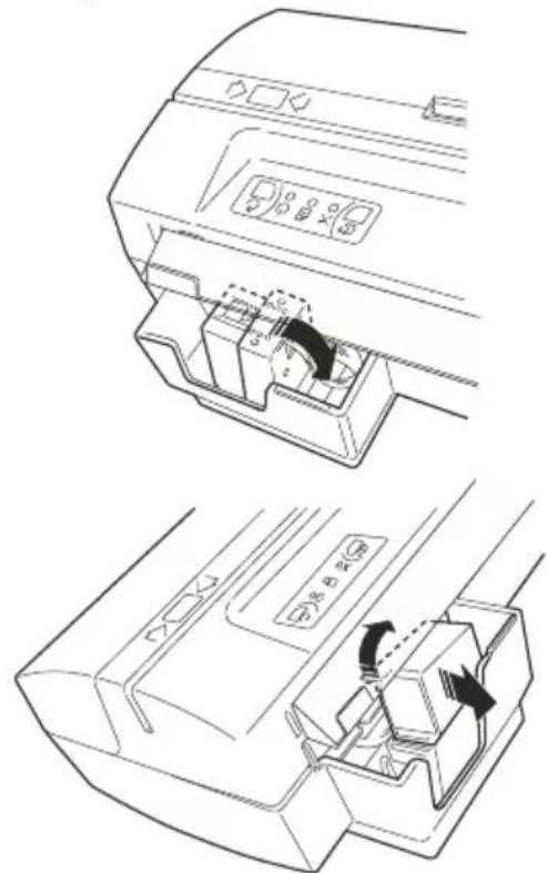
- Switch off the machine using the rear switch. Extract the document input tray.
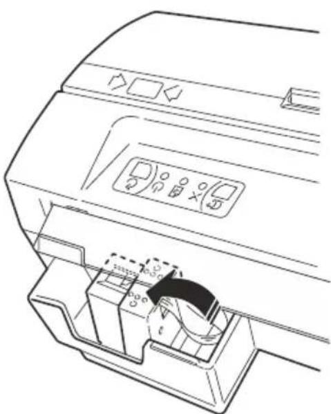
- Lower the inkjet cartridge bay with the cartridge installed by rotating it in an anti-clockwise direction.
- Remove the print cartridge by holding it at the bottom and pulling in an upward direction, pressing the lever on the cartridge to release it.
- Extract the cartridge through the rear opening on the cartridge bay.
Installing a Cartridge
NOTE: Use original print cartridges only
WARNING: Do not touch the upper contacts of the cartridge support or the inkjet cartridge nozzles.
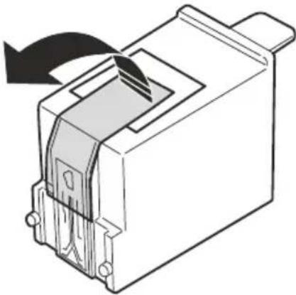
- Open the package containing the new printer cartridge and extract the cartridge, holding it from the top.
- Remove the head protection tape on the front side of the cartridge.
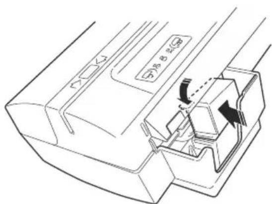
- Switch off the machine using the rear switch. Remove the document input tray.
- Insert the cartridge through the rear opening on the cartridge bay.
- Place the front of the cartridge (where the printing nozzles are located) on the base of the cartridge bay.
- Press the cartridge downwards, until you hear a click. This means that the new cartridge is inserted correctly.
CAUTION: When inserting the cartridge, be very careful not to damage the ADF module.
- Raise the cartridge support, rotating it in an anticlockwise direction to bring it to the correct operating position. Make sure that the spring mechanism brings the head to the horizontal position
- To put the scanner back into operation, mount again the document input tray.
Magnetic Stripe (SWIPE) Card Reader
Insert the card into slot, aligned to left side and with magnetic stripe to the rear (toward the input tray). With the card's bottom edge firmly in contact with the guide, slide the card to the right at a constant speed, quicker is better, until it is completely out of the machine.
During this movement, the magnetic head (illustrated in the special symbol on the scanner cover) reads the information contained on the magnetic stripe. An acoustic signal is emitted and the LED flashes when reading is successful.
The magnetic head (shown by symbol on the case) will read the magnetic stripe information during this movement. A better recognition rate is achieved with a quick and constant card movement.
INDICE
INDICE III
PRINCIPALI NORME DI SICUREZZA IV
INTRODUZIONE 1
VISIONE D'INSIEME 1
MODELLI 1
CONTENUTO DELLA CONFEZIONE 2
RIMOZIONE DEI FERMI DI IMBALLO 3
VISTA FRONTALE. 4
COLLEGAMENTI POSTERIORI 5
INSTALLAZIONE DELLO SCANNER OLISCAN 6
MONTAGGIO DEI SUPPORTI PER LO SCANNER 6
MONTAGGIO DEI VASSOIO DI INGRESSO DOCUMENTI. 7
COLLEGAMENTO DEI CAVI 9
USO DELLO SCANNER OLISCAN 10
ACCENSIONELLOSCANNER 10
OPERAZIONI PER LA SCANSIONE DI DOCUMENTI 10
| Specifications | |
| Technology | • CIS dual camera |
| Image Capture Resolution | • 200,300,600 dpi (by HW) and 75,100,150 by sw downsampling |
| Image Resolution | • 600 dpi maximum, colour, greyscale, B/W |
| Colour Depth | • B/W, 256 grey levels, 24-bit colour |
| Manageable documents | • Height: 40 to 216 mm • Length: 65 to 355 mm • ADF insertion: - Paper documents: thickness range 60 to 120 g / m² - Standard sizes: A4 and Letter, A5 and B5, A6 and B6 - Cheques • MANUAL insertion: - Accepts plastic rigid documents (max. thickness of 15 mm) - Passbooks - ID Card or Credit Card (not embossed) |
| Image format | • Bitmap, JPG, TIFF, TIFF Group 4 |
| Duplex | • Front / rear (2 sensors), up to 4 images for each pass |
| Input feeder | • Automatic, up to 30 mixed documents (depending on thickness) |
| Output tray | • Adjustable and removable, maintains original order |
| Interfaces | • 1 USB 2.0 port • 1 RS232C Serial port • 1 Hub USB 2.0 pass-through |
| Dimensions (WxDxH) | • 270 x 190 x 115 mm (without guide) • 272 x 430 x 285 (including guides and feet) |
| Weight | • Approx. 4 Kg |
| Voltage | • 100-240 V / 50-60 Hz (autorange) |
| Absorption | • 30 W max (scanning) • 6 W (stand-by) |
| Environment conditions | • Temperature: 15-35°C Humidity: 35%-85% (without condensation) |
| Noisiness | • < 54 dBA (ISO 9296) |
| Certification and quality marks | • CE, TUV NRTL, UL FCC class B • RoHS |
Options
| MICR Reader | Internal Supports CMC7, E13B |
| Validation | Inkjet, 1 line |
| Card reader | Magnetic card: 3 tracks |
| IR lighting | Pass-through Infrared lighting for microhole and watermark detection |
| USB HUB | 1 port USB HUB |
| RS-232 | 1 Serial port (RJ connector) for readers emulation |

As an ENERGY STAR partner, Olivetti has determined that this product meets ENERGY STAR UK guidelines for energy efficiency.
What is an ENERGY STAR qualified product?
An ENERGY STAR qualified product has an automatic feature that allows it to enter to a "low power mode" (sleep) after a period of inactivity (2 minutes in this product).
This means a more efficient use of energy, saves you money on utility bills and helps to protect the environment.

- Publication issued by:
- The C mark affixed to the product certifies that the product meets European Union regulations and quality requirements.
- Information to the user.
- CONTENTS
- CONTENTS III
- PRINCIPAL SAFETY REGULATIONS IV
- INTRODUCTION 1
- USING YOUR OLISCAN SCANNER 10
- ROUTINE MAINTENANCE 16
- TROUBLESHOOTING 18
- SCANNER OPTIONS 20
- Overview
- Models
- Package contents
- Optional:
- Removing the packing tape
- Front View
- Ref. Description
- Document Guide
- Input trays
- Control Panel
- Swipe card (badge) magnetic reader slot (optional)
- Top Cover
- Output tray
- Rear Connections
- Installing your Oliscan Scanner
- Mounting the scanner supports
- Installing document input tray
- Cable Connections
- Powering on the scanner
- Document scanning operations Document feeding
- Scanning A4, Letter or legal-sized documents
- Scanning cheques
- Scanning Mixed Sized Documents
- Scanning cards
- Scanning passbooks
- Scanning small-sized documents (e.g. A6 or B5)
- Scanning multicopy documents
- Double-feed sensor settings
- Control Panel
- GeneralWarnings:
- Cleaning the Scanner
- Cleaning the Cartridge
- WARNING: Do not rub against the nozzles, or use unmoistened paper, as the nozzles could become clogged.
- TROUBLESHOOTING
- General operating problems
- Scanner does not power on
- No USB connection
- Paper jams
- WARNING: During removal operations be very careful not to damage the ADF module.
- WARNING: During insertion operations be very careful not to damage the ADF module.
- SCANNER OPTIONS
- Removing and Installing an Inkjet Print Cartridge Removing a Used Cartridge
- Installing a Cartridge
- WARNING: Do not touch the upper contacts of the cartridge support or the inkjet cartridge nozzles.
- CAUTION: When inserting the cartridge, be very careful not to damage the ADF module.
- Magnetic Stripe (SWIPE) Card Reader
- INDICE
- INDICE III
- PRINCIPALI NORME DI SICUREZZA IV
- INTRODUZIONE 1
- USO DELLO SCANNER OLISCAN 10
- Options
Brand : OLIVETTI
Model : Oliscan A600
Category : Scanner