ES1211ZAMUU - Range hood Atag - Free user manual and instructions
Find the device manual for free ES1211ZAMUU Atag in PDF.

User questions about ES1211ZAMUU Atag
0 question about this device. Answer the ones you know or ask your own.
Ask a new question about this device
Download the instructions for your Range hood in PDF format for free! Find your manual ES1211ZAMUU - Atag and take your electronic device back in hand. On this page are published all the documents necessary for the use of your device. ES1211ZAMUU by Atag.
USER MANUAL ES1211ZAMUU Atag
instructions for use cooker hood
ATAG
ES1011MAM ES1211UAM
ES1011UAM ES1211AAM
ES1011TAM ES1211ZAM
ES1092MAM ES1292NAM
ES1211MAM ES1292MAM
ES1211NAM ES1511MAX
ES1211MAX ES1511MAM
Uw afzuigkap
Inleiding 4
Veiligheid
Let op! 5
Gebruik
Bediening 7
Onderhoud
Reinigen 13
Metalen vetfilters 14
Extra accessories 28
Inleiding

Metal grease filters 14
Active carbon filters 16
Installation
General 17
Electrical connection 18
Building in dimensions 19
Appendice
Disposal 27
Additional accessories 28
Introduction

When you have read these instructions for use, you will quickly be aware of all the facilities the appliance can offer you. You can read about safety and how you should look after the appliance.
Keep the instructions for use and the installation instructions. Any later user of this appliance could benefit from them.
Attention!

Make sure the appliance is installed by an authorised installer (see "Installation" chapter). Do not connect the appliance to the flow network before completing the installation.
- Connect the appliance in accordance with the applicable regulations in your area.
- We advise you to wear protective work gloves during the installation of the cooker hood due to possible sharp edges.
- The appliance has been manufactured in accordance with the latest safety standards. However we do advise that mentally handicapped, disabled or retarded individuals do not use this appliance without the proper supervision of a competent person. The same applies to children.
- Never use the cooker hood when the grease filter has not been properly installed!
- Do not lean against the cooker hood.
- The hood must never be used as a support surface unless specifically indicated.
- Make sure there is sufficient circulation when you use the cooker hood on a gas hub.
- The exhaust exit must never be connected to a smoke duct which is also used for other heating appliances.
- Never flambé under the cooker hood and always clean the filters on time. Frying needs to be done under constant supervision to prevent the heated fat from catching fire.
- The cooker hood needs to be cleaned regularly (at least once a month) on the inside as well as on the outside. When the filters are insufficiently cleaned or replaced, this will result in a fire hazard.
- If the connection cable becomes damaged, it should be replaced by the manufacturer's service department or by a person with equivalent qualifications, in order to prevent dangerous situations from arising.
- Accessible parts may become hot when used with cooking appliances.
- First disconnect the appliance from the socket when you replace the lights!
- Only use identical lamps with the wattage indicated. Only use the cooker hood with lamps installed to reduce the risk of electrical shock.
Attention!
- The grease filters become hot during operation. Wait a minimum of 30 minutes after cooking before cleaning it.
- The main current must be switched off during reparation or cleaning. Remove the plug from the mains current or turn the switch in the meter cupboard to zero.
- Grease and oil are flammable when they are overheated. Stay in the vicinity of the cooker when preparing food.
- We will not accept any responsibility for any faults, damage or fires caused to the appliance as a result of the non-observation of the instructions included in this manual.
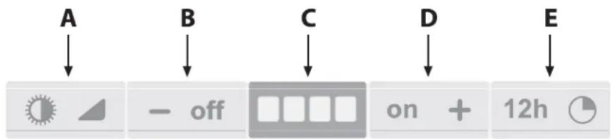
Controls
Warning!
- When activating or deactivating the operations or the alarm, the motor and lights must be switched off.
- This product is supplied with an acoustic indicator (buzzer). Each time any button is pressed, this is confirmed by an acoustic indicator.
- This function can be deactivated or activated, by simultaneously pressing the ON and TIMER buttons for five seconds.
- If your product is a FILTER version, it is necessary to activate the active carbon filters indicator function which you find in the paragraph regarding this function.
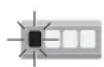
Button A

Light (Softlight)
Starting:
A brief pressure on the light button will turn on the light at the maximum intensity, activating the fast softlight function.
Adjustment:
By keeping the light button pressed, the intensity can be adjusted from maximum to minimum and viceversa.
Switching off:
Quick pressure of the light button.
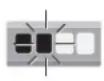
Button B
OFF and Speed reduction
Adjustment:
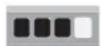
A brief pressure of the OFF button will reduce the motor speed. For example the indication on the display goes from speed 3 to speed 2.
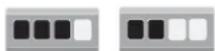
speed 3 speed 2
Switching off:
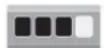
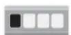
If the operating speed of the motor is set on level 1 of the display, a brief pressure of the OFF button will switch off the hood.

speed 1
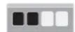
If the OFF button is pressed for at least 2 seconds, regardless from the selected motor speed, the hood will switch off.
OFF
Display C
Display
The display can alternate GREEN LEDs which indicate the motor speed, with RED LEDs which indicate the alarm status (See special functions).
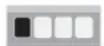

speed 1 speed 2 speed 3 speed 4
Button D
ON and Speed Increase
Starting:
In order to turn on the hood press button ON.
Adjustment:
A brief pressure of the ON button will increase the speed of the motor a step at a time.
1

2
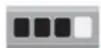
3

4
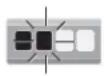
INTENSIVE speed function:
If the ON button is kept pressed for about 2 seconds, the INTENSIVE speed function is activated for 10 minutes; after this time, the previously set speed will be restored.
When the function is active LED 4 will flash

If you want to interrupt it before the 10 minutes have expired press the button again.
Button E
Timer
Operation:
The Timer button times the aspiration speed of the hood when it is activated for 10 MINUTES. After this time has elapsed the appliance will switch off.
Activation:
In order to activate the function apply a light pressure to the Timer button.
When the function is active the LED indicator of the set speed starts flashing.
When the lights are on, at the end of the Timer function, these automatically reduce the light intensity by 30 - 40% .
In order to deactivate the function, before the predetermined time, a further pressure of the Timer button, will switch off the appliance.
Warning!
If the intensive speed is operating, the Timer cannot be activated.
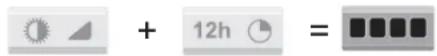
Clean Air function
Special Functions (Button E):
This function guarantees the continuous recycling of the air in the kitchen for a maximum of 12 hours. By keeping the Timer button pressed for 4 seconds, when the appliance is switched off, the "CLEAN AIR" function is activated. This turns on the motor for 10 minutes every hour at the first speed; LED 4 flashes with an interval of 1 second ON and 2 seconds OFF. After this time the motor is switched off and LED 4 remains fixed on the display; after another 50 seconds the motor starts again for another 10 minutes and so on.
In order to deactivate the "clean air" function press any button except for the lights one.
Alarm indicators
Active carbon/grease filter saturation:
When the LEDs on the display turn Red this means that the filters must be replaced or washed.
A - Anti grease filters:
When on the display the LED 1 is RED and starts flashing, it means that the hood has been running for 30 hours and that the anti-grease filters have to be cleaned.
In order to reset the electronic memory press the OFF button for 5 seconds until LED 1 stops flashing.
B - Active Carbon filters:
When on the display the LED 2 is RED and starts flashing, it means that the hood has been running for 120 hours and that the active carbon filters have to be cleaned or replaced.
In order to reset the electronic memory press the OFF button for 5 seconds until LED 2 stops flashing.
Activation of the function for the indication of inserted active carbon filters:
By pressing simultaneously the OFF and ON buttons for 5 seconds the active carbon filters indicator function is activated with an acoustic indicator of the Buzzer and the switching on for 1 second of all GREEN LEDs.
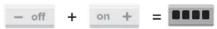
Deactivation of the inserted filters indicator function:
By pressing simultaneously the OFF and TIMER buttons for 5 seconds the active carbon filters indicator function is deactivated with an acoustic indicator of the Buzzer and the switching on for 1 second of all RED LEDs.
- In order to check if the electronic memory has been activated or deactivated on the active carbon filters indicators, press simultaneously the buttons LIGHT and TIMER for 5 seconds.
- if the function is active, the screen will display all the GREEN LEDs for 3 seconds.
- if the function is not active, the screen will display all the RED LEDs for 3 seconds.
Warning!
- Check that the Buzzer function has not been deactivated (see the warning at the beginning of the instructions of this control).
Controls

Button A
The on / off button switches on and off the whole hood (motor and lights).
By pressing the button A the motor starts at 1st speed.
Button B
From the OFF position, press once for the 1st speed, twice for the 2nd speed and three times for the 3rd speed. In order to activate the intensive speed, press the button for 5 seconds regardless of the status of the hood. For each speed only the led indicating the set speed will turn on. The intensive speed is indicated by the flashing of the led indicating speed 3. The duration of the intensive speed is 10 minutes; after this time the hood goes back to the last set speed. In order to remove the intensive speed press the power button and the hood will switch off, or press the Fan speed button and the speed goes back to the previously set one. Speed of the hood with cyclic trend.
Button C
There are three light levels: high, medium, low.
From the off position press once for the high level, twice for the medium level, three times for the low level and four times to turn the lights off.
The level of the lights has a cyclic trend: High, medium, low, off.
Button D
With any type of speed (excluding the intensive speed), by pressing the button, the timer function is activated for 15 minutes. After this time has elapsed the hood will turn off (motor and any light on).
Indicator E
The lights indicator will switch on when the lights are on at any level.
Indicator F
After 30 minutes of operation, the led of the filters indicator will switch on, not flashing indicating that the anti-grease filters have to be washed. To reset the function (with the hood off), press the Fan speed button for 5 seconds. After this operation, the led of the filters indicator turns off and the setting of the 30 hours starts again from the beginning. After 120 hours the led will flash continuously. This means that the carbon filters have to be replaced (if present). To reset the function (with hood off) press the Fan speed button for 5 seconds. After this operation, the led of the indicator turns off and the setting starts again from the beginning.
Indicator G
With the hood off, press the Power button (A) for 5 seconds to activate the clean air function. This will switch on the motor at speed 1 for 10 minutes every hour. The light indicator will switch on without flashing and the led of the 1st speed will switch on. In the remaining 50 minutes the light indicator will flash. The function can be deactivated by pressing any button except for the lights one.
Cleaning
Attention!
Before performing any maintenance operation, isolate the hood from the electrical supply by switching off at the connector and removing the connector fuse. Or if the appliance has been connected through a plug and socket, then the plug must be removed from the socket.
The cooker hood should be cleaned regularly (at least with the same frequency with which you carry out maintenance of the fat filters) internally and externally. Do not use abrasive products. Do not use alcohol!
Attention!
Failure to carry out the basic cleaning recommendations of the cooker hood and replacement of the filters may cause fire risks. Therefore, we recommend oserving these instructions. The manufacturer declines all responsibility for any damage to the motor or any fire damage linked to inappropriate maintenance or failure to observe the above safety recommendations.
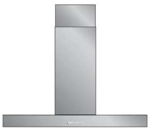
Cooker hood
Clean the cooker hood with soapy water and a soft cloth. Then wipe with clean water to rinse. Do not use aggressive cleaning agents such as soda. The cooker hood paintwork will stay looking nice if you wax it occasionally.

Stainless steel cooker hoods
Do not use any sort of scourer. Treat with a stainless steel care product and polish with the structure of the stainless steel.
Metal grease filters
These must be cleaned once a month (or when the filter saturation indication system – if envisaged on the model in possession – indicates this necessity) using non aggressive detergents, either by hand or in the dishwasher, which must be set to a low temperature and a short cycle. The openings must be placed downwards to let the water run out of the filters. The cleaning agents will make the aluminium filter turn dull, this is normal.
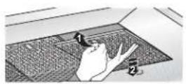
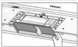
Removing filter cassette
- Switch off the flap and lighting.
- Using the recess, press the filter backwards and tip it downwards at the front.
- Remove the filter from the hood.
Cleaning
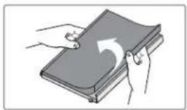
You can clean the filters in the dishwasher. Allow them to dry fully before reinstalling them in the hood.
The filters may also be cleaned by hand.
Clean the filters in water and washing-up liquid and rinse them. Allow the filters to dry fully. The underside of the extractor hood can be cleaned with a mild cleaning agent and a moist cloth. Then dry it off with kitchen towel or a dry cloth.
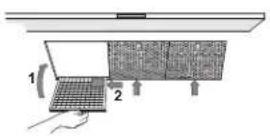
Reinstalling filter cassette
The filter has to be installed with the locking mechanism to the side. Open the locking mechanism. This pulls the projections to the side of the filter inwards. When installing the filters hold the locking mechanism in this position.
- Push the projections at the side of the filter into the openings provided for this purpose at the side of the extractor hood.
- Hinge the filter upwards.
- Release the locking mechanism. The projections at the side of the filter move outwards into the openings provided for this purpose at the side of the extractor hood.
The filter is now correctly positioned.
Attention!
Make sure you install the antigrease filters back in their original position (see figure).
The antigrease filters have to be fitted correctly in place to ensure perfectly efficient suction.
Active carbon filters:
The active carbon filters are used to purify the air that is sent back into the room and its function is to mitigate the unpleasant odours produced by cooking. Regenerable active charcoal filters must be washed by hand, with non abrasive neutral detergents, or in the dishwasher at a maximum temperature of 65^ (the washing cycle must be complete without dishware). Remove excess water without damaging the filter, remove the stainless steel casing, and let the mat dry in the oven for at least 15 minutes approximately at a maximum temperature of 100^ . To keep the regenerable charcoal filter functioning efficient this operation must be repeated when the indicator starts flashing. The charcoal mat must be replaced at least every 3 years or when the mat is damaged. Before remounting the anti-grease filters and the regenerable active charcoal filters it is important that they are completely dry. To transform the hood from a ducting version into a filtering version, ask your dealer for the charcoal filters and follow the installation instructions.
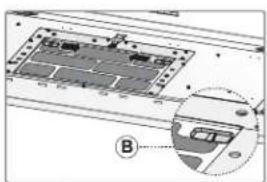
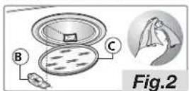
Substitution of active carbon filters:
To replace the active carbon filters you must remove the antigrease filters and then, press the two buttons on the side B of the active carbon filter into the interior. To remove the filter pull it down. To reassemble the part, simply perform the procedure in reverse.
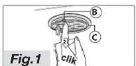
To replace a halogen bulb B, press the glass cover C as shown in figure 1
Attention:
Replace the halogen bulb with one of the exact same type. Do not touch a halogen bulb with bare hands, and make sure you put the glass cover C (figure 2) back in place after replacing the bulb.
Attention!
If instead the hood is fitted with LED bulbs, these have to be replaced by a specialized technician. Do not attempt to replace LED bulbs yourself.
General
This appliance should be connected to the power supply by a qualified technician who is familiar with, and works according to the correct safety regulations. This appliance meets the European requirements.
Important that you know:
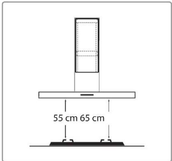
- The minimum distance between the supporting surface for the cooking vessels on the gashob and the lowest part of the range hood must be not less than 65~cm . For use with an electric, ceramic or induction hob, this distance must be at least 55~cm .
- If the cooker hood is to be fitted to an existing duct no other appliances, such as a geyser or heater, may be connected to that same duct.
- Consider local regulations with respect to the ventilation of gas appliances.
- The shorter the duct, and the fewer the bends in it, the better the cooker hood will work.
- Before you start drilling check that there are no installation cables present.
- The connecting pipe for the cooker hood has a diameter of 120, 125 or 150~mm . It is best also to use a flue pipe of the same diameter.
- The installation material supplied with this range hood is designed for fixing to reinforced concrete or masonry walls. For some types of walls you may need special plugs and screws.
Connection
Electric connection for model: ES1011MAM, ES1011UAM, ES1092MAM, ES1211MAM, ES1211NAM, ES1211UAM, ES1211AAM, ES1211ZAM, ES1292NAM, ES1292MAM, ES1511MAM.
The appliance has been manufactured as a class II, therefore no earth cable is necessary.
Make sure the supply voltage ratings correspond with those stated on the appliance data plate. The connection to the mains is carried out as follows:
BROWN = phase L
BLUE = phase N.
Electric connection for model: ES1011TAM, ES1511MAX, ES1211MAX.
This appliance is manufactured in class I, it must therefore be connected to the earth system.
Connection to the power mains must be carried out as follows:
BROWN = Phase L
BLUE = N neutral
YELLOW/GREEN = ① earth.
The neutral cable is to be connected to the clamp with symbol N while the YELLOW/GREEN cable is to be connected to the clamp next to the earthing symbol
During the electrical connection make sure that the electrical socket is equipped with earth connection.
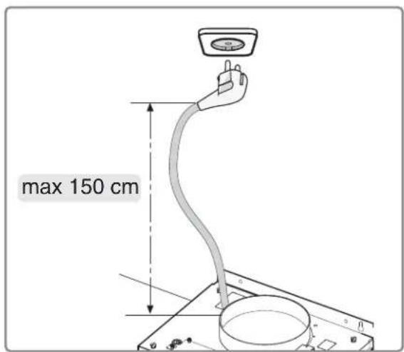
This hood has been provided with a power plug. When installing the hood, make sure that this plug remains accessible. We recommend installing the wall socket out of view, behind the chimney cover.

Attention:
If you want to make a fixed connection, ensure that a multi-pole switch with a distance between contacts of 3mm is installed in the supply cable.
Building in dimensions
Type:
ES1011MAM
ES101UAM
ES101TAM
ES1092MAM
ES1211MAM
ES1211NAM
ES1211MAX
ES121UAM
ES1211AAM
ES1211ZAM
ES1292NAM
ES1292MAM
ES1511MAX
ES1511MAM
Clearance required:
The minimum distance between the supporting surface for the cooking vessels on the gashob and the lowest part of the range hood must be not less than 65~cm . For use with an electric, ceramic or induction hob, this distance must be at least 55~cm .
You are advised to install this product with the help of a second person.
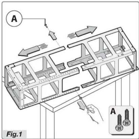
- Unpack the structure and remote the two screws A to separate the top part from the bottom one (Fig.1).
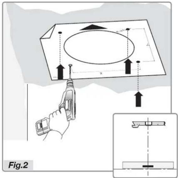
Take the hole template and place it on the ceiling, with the arrow on the same side as the hood's controls (Fig.2).
For the mounting work, use screws and expansion dowels suited to the type of wall (e.g. reinforced concrete, plasterboard, etc.). If screws and dowels are provided with the hood, make sure beforehand that these are suitable for the type of wall on which the hood is to be mounted.
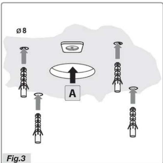
- Drill the four 8 holes in the ceiling and insert the four dowels.
- Prepare the air evacuation hole A (Fig.3).
- Connect the flexible pipe to hole A.
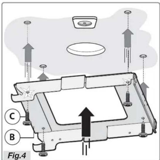
Take bracket B and fasten it on the ceiling with the four screws C (Fig.4).
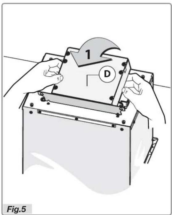
- Before installing the hood, fasten the electrical box D.
- Lift the electrical box (Fig.5).
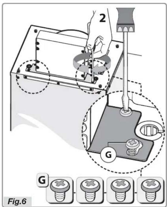
- Position the bracket in line with the four screws G already in the bushing and do them up as shown in Figure 6.
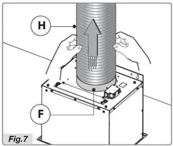
- Fasten the air evacuation pipe H (not provided) on the connecting flange F as shown in figure 7.
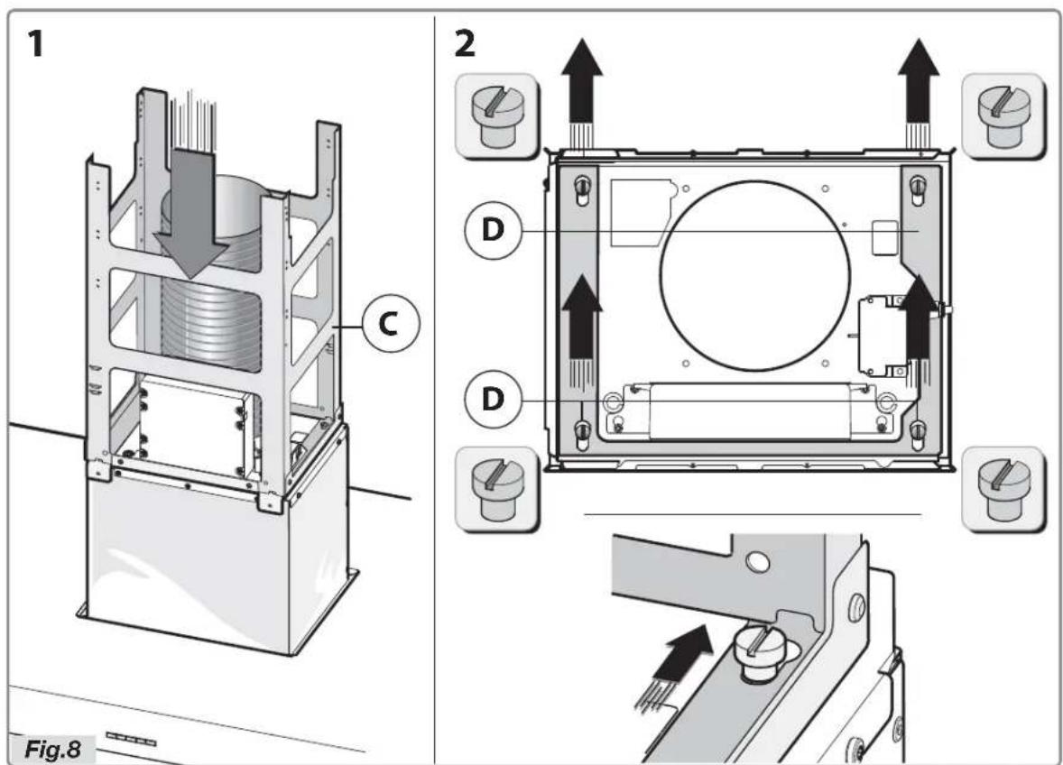
- Take the bottom structure C and fasten it on the motor bushing, fitting the bottom structure by means of its slots (Fig.8).
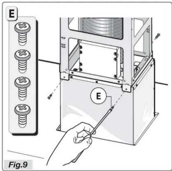
- Fasten the structure C on the motor bushing with the 4 screws E (Fig.9).
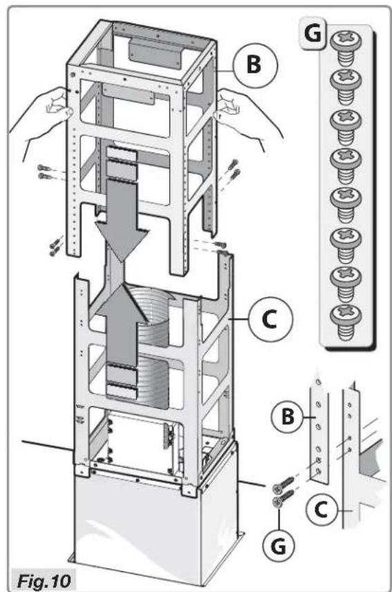
Take the top part of the telescopic structure B and insert it on the bottom one C.
- Adjust the height as required, referring to the measurements in Figure 10, and fasten with the 8 screws G provided.
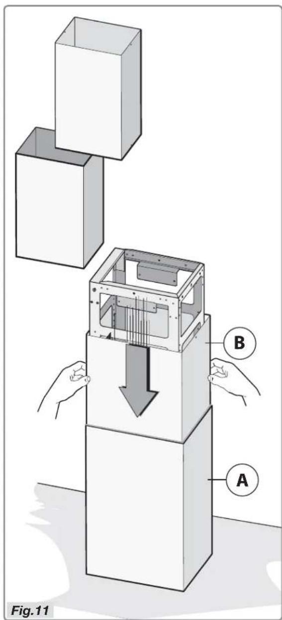
- Connect the bottom chimney A to the top one B as shown in Figure 11.
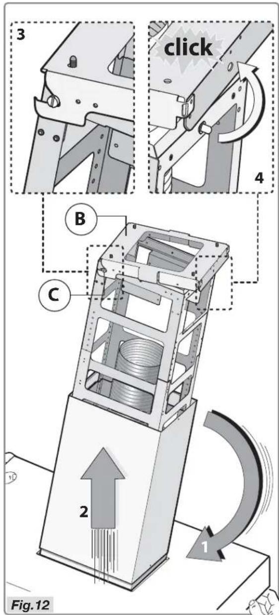
Take the hood and incline it as shown in Figure 12 - step 1.
- Using the 2 side pivots C already on the structure, hang the hood on the bracket B Figure 12 - steps 2-3.
- Move the hood into position, to engage the safety pivot in the hole of the bracket B Figure 12 - step 4.
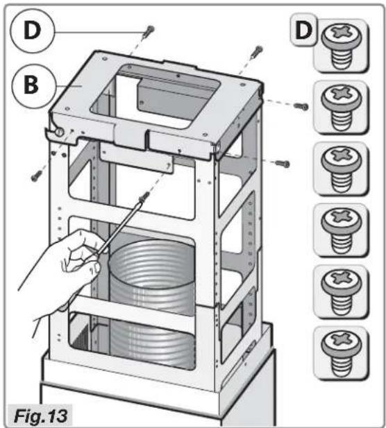
- Attention! Fasten the hood immediately on the bracket B with the 6 screws D (Fig.13).
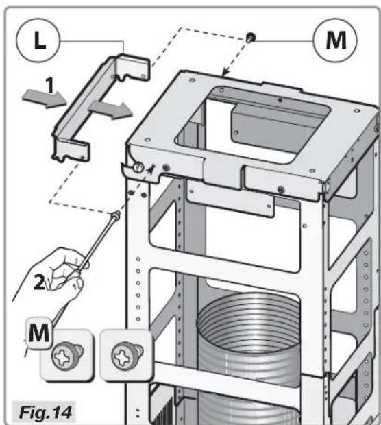
- Take the safety bracket L and fasten it definitively on the telescopic structure with the two screws M as shown in Figure 14 - steps 1-2.
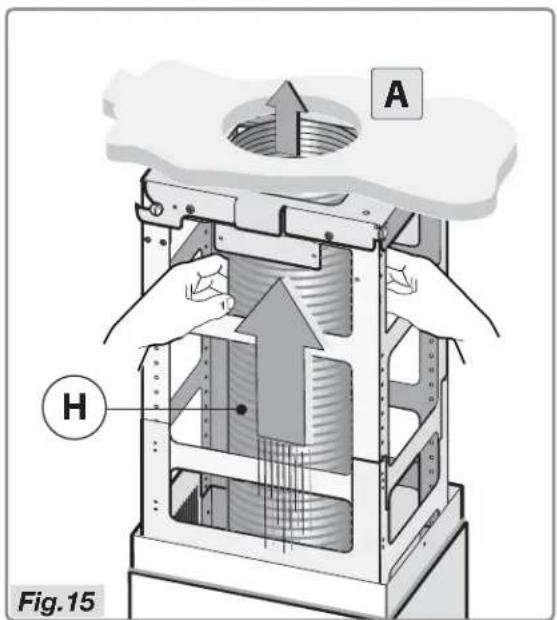
- Connect the flexible pipe H (not provided) to the air evacuation hole A (Fig.15).
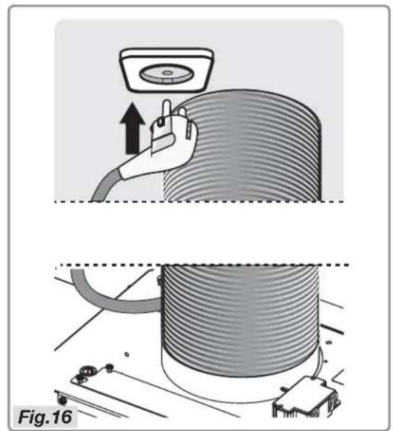
- Connect to the electrical mains (Fig.16).
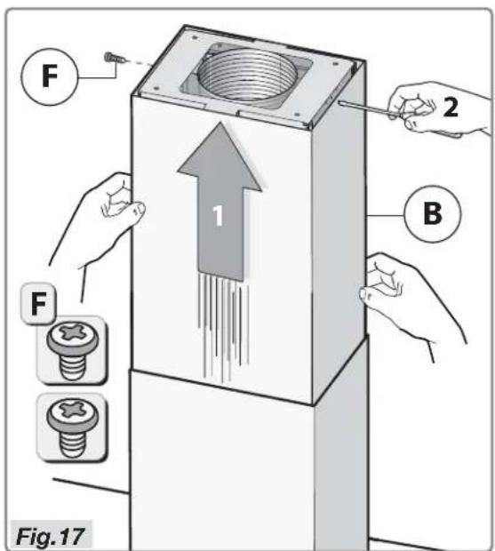
- Connect the top chimney B to the structure using the two screws F (Fig.17).
Disposal
Disposal of appliance and packaging
By ensuring this product is disposed of correctly, you will help prevent potential negative consequences for the environment and human health, which could otherwise be caused by inappropriate waste handling of this product. The local authorities can provide you with the relevant information.
The packaging of this appliance is recyclable. It could have been made from:
cardboard;
polythene foil (PE);
CFK-free polystyrene (PS-hard foam).
You need to dispose of these materials responsibly in accordance with official regulations.
To draw attention to the fact that the segregated processing of electric household appliances is compulsory, this appliance carries the symbol of a crossed-out dustbin. This means that at the end of its working life, you may not dispose of the appliance as household refuse. Instead, you should hand it in at a special refuse collection centre run by the local authority or at a dealer's providing this service.
Segregated processing of household appliances avoids any negative effects on the environment and public health that might otherwise occur.
It enables the recovery of the materials used in the production of this appliance, thus realising considerable savings in terms of raw materials and energy.