
NC 451 - Coin and bill counter OLYMPIA - Free user manual and instructions
Find the device manual for free NC 451 OLYMPIA in PDF.
| Product Type | Banknote and Coin Counter |
| Brand | Olympia |
| Model | NC 451 |
| Dimensions (L × D × H) | 250 mm × 230 mm × 135 mm |
| Weight | 3.2 kg |
| Power Supply | 110-240 V (AC), 50/60 Hz, 40 W |
| Current Consumption | 75 W |
| Built-in Battery | No (NC 452 only) |
| Hopper Capacity | 100 bills (old) / 200 bills (new) |
| Stacker Capacity | 100 bills (old) / 200 bills (new) |
| Compatible Bill Size | 50 mm × 110 mm to 85 mm × 180 mm |
| Counting Speed | Up to 1,000 bills/minute |
| Main Functions | Simple counting, add, batch function (preset 100), UV and magnetic detection |
| Counterfeit Detection | UV and magnetic (can be disabled) |
| Sensor Cleaning | Brush provided; clean after each use |
| Case Maintenance | Soft, lint-free cloth, without solvent |
| Safety Instructions | Keep out of reach of children; do not insert foreign objects; use on a stable surface |
| Repairability | Repairs only by qualified personnel; opening prohibited |
| Warranty | Return to the place of purchase with original packaging and receipt |
| Disposal | Do not dispose of with household waste; take to a recycling center |
Frequently Asked Questions - NC 451 OLYMPIA
User questions about NC 451 OLYMPIA
0 question about this device. Answer the ones you know or ask your own.
Ask a new question about this device
Download the instructions for your Coin and bill counter in PDF format for free! Find your manual NC 451 - OLYMPIA and take your electronic device back in hand. On this page are published all the documents necessary for the use of your device. NC 451 by OLYMPIA.
USER MANUAL NC 451 OLYMPIA
GB IE CY Bank Note Counter with Validation Function
natural_image
Exterior view of a Olympus NC-81 digital counter with control buttons and internal modules (no readable text or symbols beyond branding)DEUTSCH
Bedienungsanleitung


natural_image
Illustration of a stack of papers with a paperclip and cord (no text or symbols)B
C

D
natural_image
Diagram showing a ball rolling down an inclined plane with a shaded grid and directional arrows indicating motion (no text or symbols)
natural_image
Diagram showing a striped object interacting with a rod and a circular object, with an arrow indicating direction (no text or symbols)D
natural_image
Diagram showing a rotating rod with a shaded plate and a downward arrow, no text or symbols presentnatural_image
Exterior view of a digital payment machine with control panel and buttons (no visible text or symbols)natural_image
Internal view of a mechanical device with visible internal components and a numbered label '24' (no text or symbols on the device itself)24 Einzugsrollen
Service-Center Hattingen
Zum Kraftwerk 1
45527 Hattingen
Please read the following information and observe it and keep
this operating manual in a safe place for future reference!
Safety Instructions

WARNING!
- Risk of suffocation through small parts, packaging and protective foils!
→Keep the product and packaging out of reach of children!

CAUTION!
- Risk through infeed rollers!
→Keep fingers, hair etc. away from the infeed. - Risk of tripping through improperly laid cable!
→Lay the cables so that nobody can trip over them.
ATTENTION!
- Risk of property damage!
→Ensure no foreign bodies, such as paper clips, rubber bands, etc. get into the infeed.
→Prevent exposing the device to environmental influences such as smoke, dust, vibration, chemicals, moisture, heat or direct sunlight.
→Repairs may only be carried out by properly trained specialists.
Intended Use
The bank note counter with verification functions, subsequently referred to as a bank note counter, serves to count bank notes. Any other use is considered unintended use. Unauthorised modification or reconstruction is not permitted.
Under no circumstances open the bank note counter or complete any repair work yourself.
This device checks two of the features of the bank notes (ultraviolet feature and magnetic feature) to ensure they are not counterfeit. If other features of the notes have been falsified or are missing, this bank note counter cannot detect the bank notes as being critical. In the same way, an authentic bank note can be detected as being faulty due to soiling or some other external influence. Therefore, test bank notes detected as being faulty several times and, in the case of doubt, consult your bank institution.
Scope of delivery
NC 451
• NC 451 bank note counter
- Brushes
- Operating manual
NC 452
• NC 452 bank note counter
- Brushes
- External power adapter
- Operating manual
Display and Notation
→Action to be completed
→Result of the action

Helpful information
Operating Elements
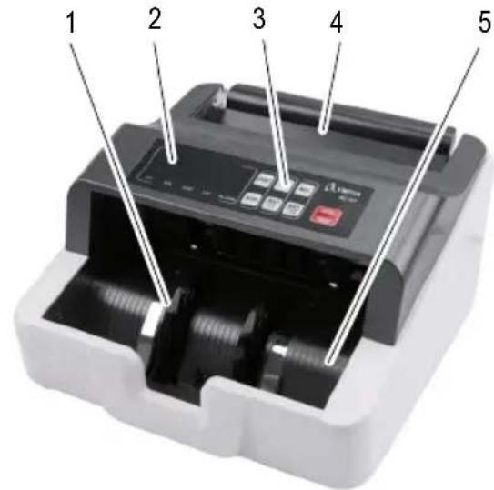
1 Separating wheel
2 Display (left and right-hand side of the display)
3 Keypad
4 Infeed tray
5 Output tray
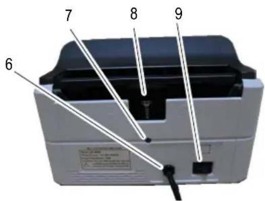
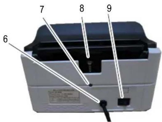
6 NC 451 power plug
NC 452 power supply port for external power adapter (not illustrated)
7 Locking screw
8 Adjusting screw
9 On/Off switch
Keypad
The illustration depicts the keypad [3] of the bank note counter.
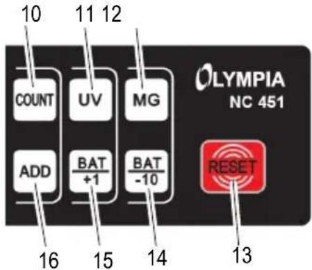
10 COUNT = Counting without activating/deactivating sensors
11 UV = Activate/Deactivate the ultraviolet test
12 MG = Activate/Deactivate the magnetic strip test
13 RESET = Clear the current result
14 BAT -10 = Function for batches (reduce the number by 10)
15 BAT +1 = Function for batches (increase the number by 1)
16 ADD = Activate/Deactivate the Add function
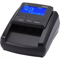
Display
The illustration depicts the display [2] during the self-diagnosis.
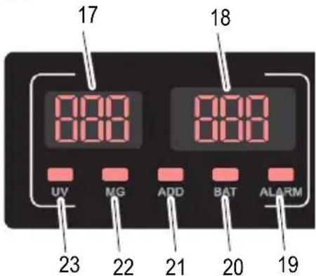
17 Result of the previous count function or preset quantity for bank note batches
18 Number of bank notes
19 ALARM = Error detected
20 BAT = Batch function is activated
21 ADD = Add function is activated
22 MG = Magnetic strip sensor is activated
23 UV = Ultraviolet sensor is activated
Operation
Connecting the Bank Note Counter
i If the bank note counter will not be used for a longer period, disconnect it from the power outlet.
NC 451
→Connect the power plug [6] to a properly installed power socket.
NC 452
→Connect the external power adapter to the power supply port [6] of the bank note counter.
→Connect the power plug to a properly installed power socket.
Switching the Bank Note Counter On/Off
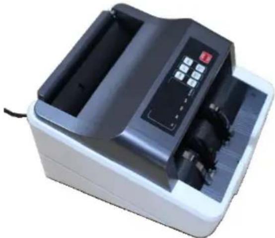
The bank note counter is switched on and off using a switch [9] on the rear of the machine.
After switching the bank note counter on, it completes a self-diagnosis. During the self-diagnosis, BBB and BBB appear in the displays [17, 18]. When the self-diagnosis has finished without any errors, 0 appears in the displays [17, 18].
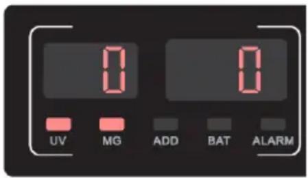
If an error is detected, it is indicated in the right-hand display [18] (refer to Clearing Errors).
Battery Operation
NC 452
The bank note counter can be operated either using the mains power or a rechargeable battery.
Before the device can be operated via the battery for the first time, the battery must be fully charged.
→Connect the external power adapter to the power supply port [6] of the bank note counter.
→Connect the power plug to a properly installed power socket.
i The charging time required is about 8 hours.
→When the charging process has finished, disconnect the power adapter from the power supply port [6] of the bank note counter.
→Disconnect the power plug from the power socket.
→The bank note counter can now be used as a portable device.
Validation Tests
Selecting the Features to be Tested
Before inserting the bank notes, select which features (magnetic and/or ultraviolet) you want to test.
→Press the MG button [12].
The magnet sensor used to detect the magnetic ink is activated/deactivated. When activated, the sensor is indicated in the display. MG [22] appears in the display.
→Press the UV button [11].
→The ultraviolet sensor for detecting UV components is activated/deactivated. UV [23] appears in the display.
Preparing Bank Notes
i The best results are achieved after a warm-up phase of 3 minutes.
Bright ambient light can affect the sensor and falsify results.
Pay attention to the following points to prevent malfunctions.
natural_image
Simple line drawing of a stack of papers with a paperclip and cord (no text or symbols)
natural_image
Simple line drawing of a rectangular shape with a shaded triangular section and a small irregular cutout (no text or symbols)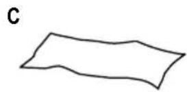
natural_image
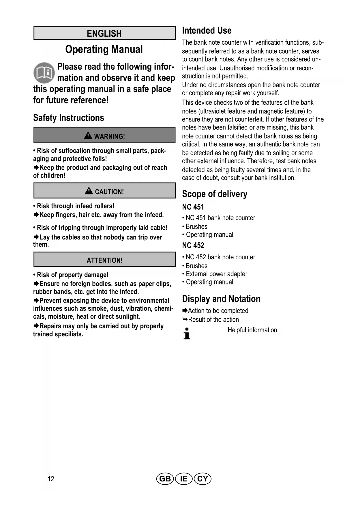
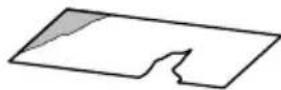
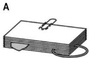
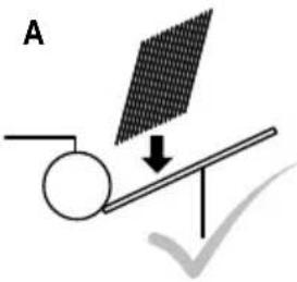
Simple geometric shape resembling a rectangle with a triangular cutout on the left side (no text or symbols)→Check the batch of bank notes for paper clippings, paper clips, rubber bands and other foreign bodies and remove them before inserting the bundle in the machine (Figure A).
→Do not insert any damaged bank notes (Figure B).
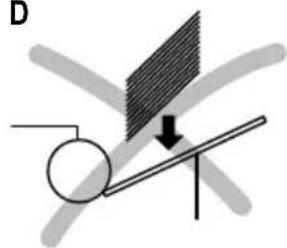
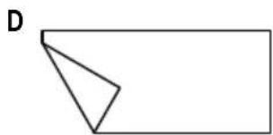
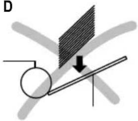
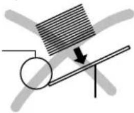
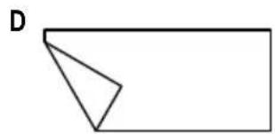
→ Smoothen any creased and folded bank notes before inserting them (Figure C/D).
→Do not insert any bank notes which are stuck together in the bank note counter.
→Fan out the bank notes to separate them prior to insertion.
Inserting Bank Notes
natural_image
Diagram showing a ball rolling down an inclined plane with an arrow indicating motion, no text or symbols present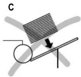
natural_image
Diagram showing a rotating rod with a striped surface and an arrow indicating direction (no text or symbols)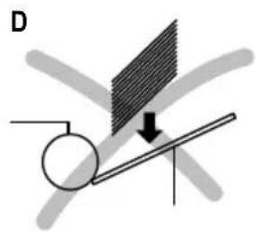
natural_image
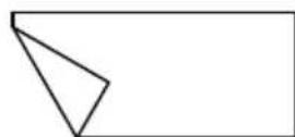
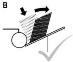
Diagram showing a rotating rod with a shaded plate and an arrow indicating downward motion (no text or symbols)→ Slide and fan the bank notes in the batch so that the top bank note is somewhat lower than the one following. Insert the bank notes in the infeed tray [4] (Figure A).
Or
→Insert the bank note bundle vertically in the infeed tray [4] and push the bank note bundle to the rear so that the bank notes shift against each other (Figure B).
→ Counting starts automatically.
i Bank notes which have been inserted incorrectly, as illustrated in Figures C and D, lead to an improper count or a malfunction.
i Since the security features of bank notes are provided on both sides, the process for detecting counterfeit bank notes is performed reliably on both sides.
Functions
→Select the required function.
Counting
This function counts the number of bank notes and, depending on the sensor setting, their validity. During the counting process, the quantity of bank notes appears in the right-hand display [18]. If the bank notes counted are left in the output tray [5], counting resumes from the last number. If the bank notes counted are removed from the output tray [5] and a new batch of bank notes is placed in the infeed tray, counting begins from 0.
→Press the COUNT button [10].
The bank notes are counted without any verification tests (UV, MG) and discharged in the output tray [5].
Adding
When this function is activated, counting is continued even if the bank notes counted are removed from the output tray [5] and a new bundle of bank notes laid in the infeed tray [4] .
This function is particularly useful in the case of large stacks of bank notes and for heavily used and creased bank notes. Smaller stacks of bank notes can then be counted in succession. The display continues with the count of the bank notes.
→Press the ADD button [16].
→ The Add function is activated/deactivated. ADD [21] appears in the display.
Batch
This function causes counting to stop when a preset quantity of bank notes has been counted. If the batch of bank notes counted is removed from output tray [5], the display [18] skips back to and the next batch of bank notes is counted.
→ Press the BAT +1 button [15] or BAT -10 button [14].
→BAT [20] appears in the display. The preset number 100 appears in the left-hand display [17].
→ Use the BAT +1 button [15] or BAT -10 button [14] to set the number of notes you require.
The number can be increased by 1 using the BAT +1 button [15] and reduced by 10 using the BAT -10 button [14].
The number entered appears in the left-hand display [17]. The bank note counter is ready for the batch function.
i Press the RESET button [13] to deactivate the function.
Clearing Errors
Error Indicators
Error are indicated in the right-hand display [18] by means of code numbers.
i A frequent source of errors is soiling of the sensors (see Cleaning the Sensors). Following the instructions provided under "Solution".
| Code No. | Cause Solution | |
| E01 | The left-hand sensor for counting the bank notes is soiled or damaged. | Clean the sensor.If the error continues to occur, refer to the information in Chapter "Warranty". |
| E02 | The right-hand sensor for counting the bank notes is soiled or damaged. | |
| E03 | The code disk sensor is dirty or damaged | |
| E04 | The sensor in the infeed tray [4] is soiled or damaged. | |
| E05 | The stacker sensor is dirty or damaged. | |
| bF | The infeed rollers [24] rotate for more than 10 seconds but do not draw any bank notes in. | Press the RESET button [13] and repeat the counting function.If the error continues to occur, refer to the information in Chapter "Adjusting the Pressure of the Infeed Plate". |
Alarm Indicators
Alarms are indicated in the right-hand display [18] by means of code numbers. ALARM [19] appears in the display.
| Code No. C | Cause Solution | |
| EE1 | Critical bank note has been detected. Too little or no ultraviolet reaction from the bank note. | Remove the critical bank note from the output tray [5].Press the RESET button [13] to continue counting. |
| EE2 | Critical bank note has been detected. Too little or no magnetic reaction from the bank note. | |
| EE4 | Bank notes detected as half bank notes. | Remove the critical bank note from the output tray [5] and check the bank notes for signs of damage.Press the RESET button [13] to continue counting. |
| The left/right-hand sensor for counting the bank notes is soiled or damaged. | Clean the sensor.If the error continues to occur, refer to the information in Chapter "Warranty". | |
| EE5 | Doubled bank notes have been detected. | Adjust the pressure exerted by the infeed plate.Check whether the bank notes stick together.Start the counting function again. |
| EE7 | Bank note was drawn in askew. Lay the bank note in the infeed tray [4] again. | Remove the critical bank note from the output tray [5].Press the RESET button [13] to continue counting. |
| EE9 | The width of the bank note is more than 85 mm. | |
| EEA | Chained bank notes |
Maintenance
Cleaning the Sensors
Bank notes are often soiled, particularly by dust. The dirt deposits on the sensors during the counting process. Soiled sensors are the most frequent cause of malfunctions.
Clean the sensors with the brush supplied. Open the bank note counter to clean the sensors. How to open the bank note counter is described in the following steps.
→Switch the bank note counter off using the switch [9].
→Disconnect the power plug [6] from the power socket.
natural_image
Exterior view of a digital payment machine with control panel and buttons (no visible text or symbols)→ Pivot the keypad to the front.
natural_image
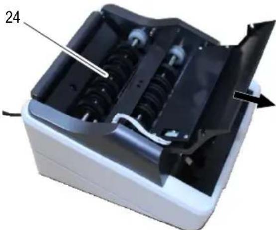
Internal view of a mechanical device with visible internal components and a numbered label '24' (no text or symbols on the device itself)24 Infeed rollers
i Clean areas which cannot be accessed using compressed air, if necessary. Compressed air can be obtained in small aerosol cans.
→Clean the sensors with the brush supplied.
→ Pivot the keypad to the rear.
Adjusting the Pressure of the Infeed Plate
The bank note counter is set-up at the factory to draw the bank notes in properly. If bank notes are no longer drawn in properly, adjust the pressure exerted by the infeed plate.
The adjusting screw [8] to alter the pressure exerted by the infeed plate is located at the rear.
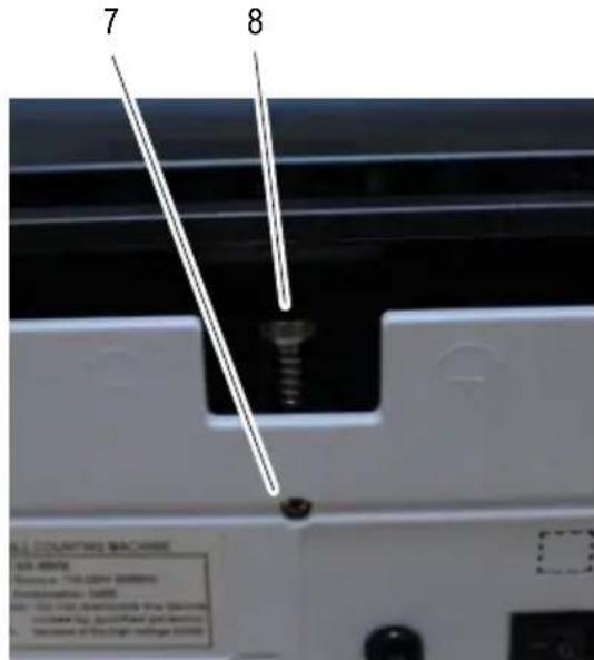
The adjusting screw [8] is secured against being adjusted inadvertently by means of a locking screw [7].
→Switch the bank note counter off.
→ Disconnect the power plug [6] rom the power socket.
→Loosen the locking screw [7] with a screwdriver.
Adjust the pressure of the infeed plate with the adjusting screw [8] so that the bank notes can slide under the infeed rollers with a little force.
→ Tighten the locking screw [7] with a screwdriver.
Technical Data
| Model NC 451 / NC 452 | |
| Functions Free counting mode (without validation test) | |
| Validation test Ultraviolet and magnetic features test | |
| Capacities: infeed and output trays | 100 old bank notes, 200 new bank notes |
| Size of countable bank notes 50 mm × 110 mm bis 85 mm × 180 mm | |
| Counting speed 1,000 bank notes / minute | |
| Power supply | |
| NC 451 | 110 - 240 V (AC), 50/60 Hz, 40 W |
| NC 452 | External power adapter: Input voltage 110 - 240 V (AC), 50/60 Hz / Output voltage 12.6 V (DC), 4 A |
| Power consumption 75 W | |
| Integrated rechargeable battery | |
| NC 451 | - |
| NC 452 | 11.1 V (DC), 2600 mAh, 28.86 Wh |
| Dimensions 250 mm × 230 mm × | 135 mm |
| Weight 3.2 kg | |
Care Instructions
→Clean the housing surface with a soft, lint-free cloth.
→ Clean the sensors with the brush supplied each time after use.
→Do not use any solvents or cleaning agents.
Disposal

In order to dispose of your device, take it to a collection point provided by your local public waste authorities (e.g. recycling centre).
According to laws on the disposal of electronic and electrical devices, owners are obliged to dispose of old electronic and electrical devices in a separate waste container.
The adjacent symbol indicates that the device must not be disposed of in normal domestic waste!
Packaging materials must be disposed of according to local regulations.
Warranty
Dear customer,
we are delighted that you have chosen this equipment.
In the case of a defect, please return the device together with the receipt and original packing material to the point of sale.
FRANÇAIS
Mode d'emploi

natural_image
Simple diagram showing a rotating rod with an arrow indicating downward motion (no text or symbols)D
natural_image
Diagram showing a rotating object on a lever with a shaded screen and directional arrow (no text or symbols)natural_image
Exterior view of a digital payment machine (no visible text or symbols)natural_image
Interior view of a device showing internal components and a labeled part (24), with no visible text or symbols beyond the number.
natural_image
Diagram showing a rolling object on an inclined plane with arrows indicating motion direction (no text or symbols)C
natural_image
Diagram showing a lever with a rotating wheel and a striped block, no text or symbols presentD

natural_image
Diagram showing a rotating rod with a shaded plate and a downward arrow, no text or symbols presentnatural_image
Exterior view of a digital payment machine with control panel and buttons (no visible text or symbols)natural_image
3D rendering of a mechanical device with internal components and a labeled part (24), showing no visible text or symbols.24 Intrekrollen

natural_image
Simple line drawing of a stack of papers with a paperclip and cord (no text or symbols)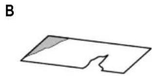
natural_image
Simple geometric shape with a shaded triangular cutout, labeled 'B' (no text or symbols within the shape)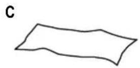
natural_image
Simple geometric shape resembling a rectangle with a triangular cutout on the left side (no text or symbols)natural_image
Diagram showing a striped object on a surface with a circular object below, and an arrow indicating direction (no text or symbols)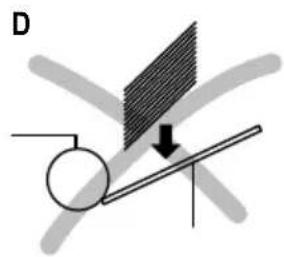
natural_image
Diagram showing a rotating rod with a shaded plate and an arrow indicating direction (no text or symbols)natural_image
Exterior view of a digital payment machine with control panel and buttons (no visible text or symbols)natural_image
Internal view of a mechanical device with visible internal components and a numbered label '24' (no text or symbols on the device itself)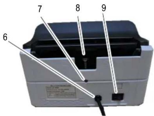
natural_image
Diagram showing a rolling object on an inclined plane with arrows indicating motion direction (no text or symbols)C

natural_image
Simple diagram showing a rotating rod with an arrow indicating downward motion (no text or symbols)D

natural_image
Diagram showing a rotating rod with a shaded plate and a downward arrow, no text or symbols presentnatural_image
Exterior view of a digital payment machine with control panel and buttons (no visible text or symbols)natural_image
Interior view of a mechanical device with visible internal components and a numbered label (24), no readable text or symbols beyond the number.24 Rodillos de arrastre

natural_image
Diagram showing a rolling object on an inclined plane with arrows indicating motion direction (no text or symbols)C

natural_image
Simple diagram showing a rotating rod with an arrow indicating downward motion (no text or symbols)D

natural_image
Diagram showing a rotating rod with a shaded plate and directional arrow, no text or symbols presentnatural_image
Exterior view of a digital payment machine with control panel and buttons (no visible text or symbols)natural_image
Internal view of a mechanical device with visible internal components and a numbered label '24' (no text or symbols on the device itself)24 Ρολά τροφοδοσίας
GB IE CY Declaration of conformity
To view the complete Declaration of Conformity, please refer to the free download available on our website www.go-europe.com.
GB IE CY All rights reserved.

- DEUTSCH
- Bedienungsanleitung
- Einzugsrollen
- Service-Center Hattingen
- Zum Kraftwerk 1
- Hattingen
- Please read the following information and observe it and keep
- this operating manual in a safe place for future reference!
- Safety Instructions
- WARNING!
- CAUTION!
- ATTENTION!
- Intended Use
- Scope of delivery
- NC 451
- NC 452
- Display and Notation
- Operating Elements
- Keypad
- Display
- Operation
- Connecting the Bank Note Counter
- Switching the Bank Note Counter On/Off
- Battery Operation
- Validation Tests
- Selecting the Features to be Tested
- Preparing Bank Notes
- Inserting Bank Notes
- Functions
- Counting
- Adding
- Batch
- Clearing Errors
- Error Indicators
- Alarm Indicators
- Maintenance
- Cleaning the Sensors
- Infeed rollers
- Adjusting the Pressure of the Infeed Plate
- Care Instructions
- Disposal
- Warranty
- FRANÇAIS
- Mode d'emploi
- Intrekrollen
- Rodillos de arrastre
- Ρολά τροφοδοσίας
- GB IE CY Declaration of conformity
Brand : OLYMPIA
Model : NC 451
Category : Coin and bill counter