
NC 455 - Coin and bill counter OLYMPIA - Free user manual and instructions
Find the device manual for free NC 455 OLYMPIA in PDF.
| Product type | Banknote counter with detection functions |
| Brand | Olympia |
| Model | NC 455 |
| Dimensions (W × D × H) | 242 mm × 276 mm × 245 mm |
| Weight | 4.7 kg |
| Power supply | 230 V (AC), 50 Hz |
| Power consumption | 90 W |
| Safety fuse | 3.15 A / 250 V |
| Hopper capacity | 200 banknotes (old), 300 banknotes (new) |
| Stacker capacity | 200 banknotes (old), 300 banknotes (new) |
| Compatible banknote size | 50 mm × 110 mm to 85 mm × 180 mm |
| Banknote thickness | 0.075 – 0.15 mm |
| Counting range | 1 – 9,999 banknotes |
| Counting speed | 1,000 banknotes/minute |
| Noise level | 60 dB |
| Operating temperature | 0 °C – 40 °C |
| Operating relative humidity | 60 – 90% |
| Main functions | Free counting, UV detection, magnetic (MG/MT), infrared (IR), batch function (up to 999), Add function, auto/manual start |
| Display | LCD screen with backlight, upper and lower display |
| External display included | Yes, connectable via RJ connector |
| Maintenance and cleaning | Clean the sensors after each use with the supplied brush; exterior surfaces with a soft, lint-free cloth; do not use solvents |
| Safety | Automatic stop in case of error, detection of suspicious banknotes (UV, magnetic, infrared), stop in case of jam or counterfeit detection |
| Available settings | Feed roller pressure (screw at rear), individual sensor activation/deactivation |
| Package contents | Counter, external display, power cable, brush, large and small drive belt, instruction manual |
| Warranty | Return the device in its original packaging with the receipt to the point of purchase |
Frequently Asked Questions - NC 455 OLYMPIA
User questions about NC 455 OLYMPIA
0 question about this device. Answer the ones you know or ask your own.
Ask a new question about this device
Download the instructions for your Coin and bill counter in PDF format for free! Find your manual NC 455 - OLYMPIA and take your electronic device back in hand. On this page are published all the documents necessary for the use of your device. NC 455 by OLYMPIA.
USER MANUAL NC 455 OLYMPIA
Service-Center Hattingen
Zum Kraftwerk 1
45527 Hattingen
Please read the following information and observe it and keep
this operating manual in a safe place for future reference!
Safety Instructions

WARNING!
- Risk of suffocation through small parts, packaging and protective foils!
Keep the product and packaging out of reach of children!

CAUTION!
- Risk through infeed rollers!
Keep fingers, hair etc. away from the infeed. - Risk of tripping through improperly laid cable!
Lay the cables so that nobody can trip over them.
ATTENTION!
- Risk of property damage!
Ensure no foreign bodies, such as paper clips, rubber bands, etc. get into the infeed.
Prevent exposing the device to environmental influences such as smoke, dust, vibration, chemicals, moisture, heat or direct sunlight.
Repairs may only be carried out by properly trained specialists.
Intended Use
The bank note counter with verification functions, subsequently referred to as a bank note counter, serves to count bank notes. Any other use is considered unintended use. Unauthorized modification or reconstruction is not permitted.
Under no circumstances open the bank note counter or complete any repair work yourself.
This device checks two of the features of the bank notes (ultraviolet feature and magnetic feature) to ensure they are not counterfeit. If other features of the notes have been falsified or are missing, this bank note counter cannot detect the bank notes as being critical. In the same way, an authentic bank note can be detected as being faulty due to soiling or some other external influence. Therefore, test bank notes detected as being faulty several times and, in the case of doubt, consult your bank institution.
Scope of Delivery
- NC 455 bank note counter
External display
Power cable
Brushes
Large and small drive belts - Operating manual
Display and Notation
Action to be completed
Result of the action

Helpful information
Operating Elements
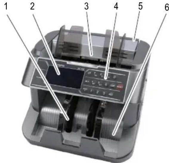
1 Separating wheel
2 Display
3 Infeed tray
4 Keypad
5 Handle
6 Output tray
7 Rating plate
8 On/Off switch
9 Adjusting screw
0 Connection port (for external display)
11 Power plug socket
12 Fuse
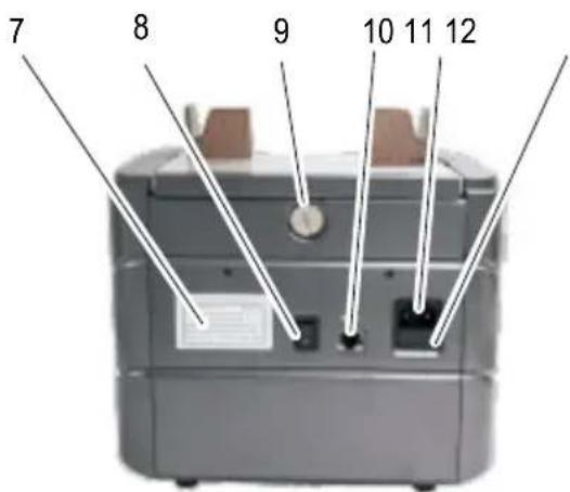
Keypad
The illustration depicts the keypad [4] of the bank note counter.
Some keys have more than one function assigned, depending on the actual situation.
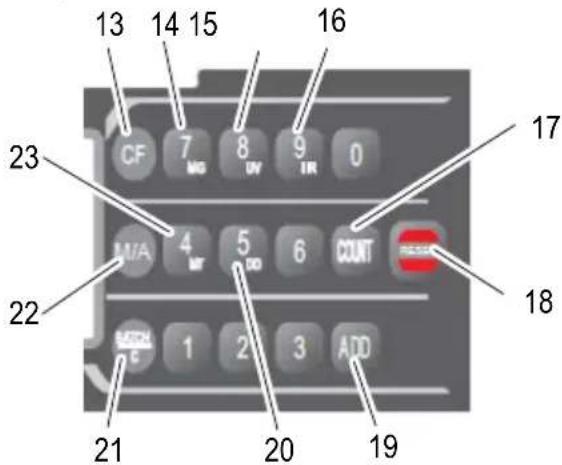
13 CF = Switch-over function
14 MG = Activate/Deactivate the magnetic strip test
15 UV = Activate/Deactivate the ultraviolet test
16 IR = Activate/Deactivate infrared test
17 COUNT = Counting without activating sensors
18 RESET = Clear the current result
19 ADD = Activate/Deactivate the Add function
20 DD = Activate/Deactivate testing the note width
21 BACH/C = Function for batches of notes
22 M/A = Start up manually or automatically
23 MT = Activate/Deactivate the advanced magnetic strip test
Display
The illustration depicts the display [2] during the self-diagnosis.
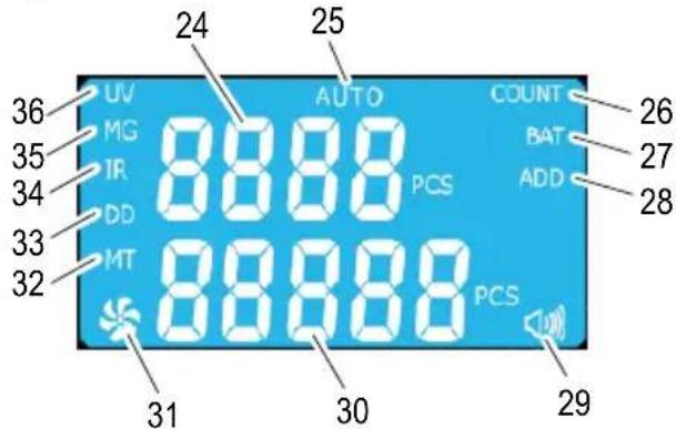
24 Top display for the result of the previous count function or preset quantity for bank note batches
25 AUTO = Automatic start is activated
26 COUNT = Counting without sensors is activated
27 BAT = Batch function is activated
28 ADD = Add function is activated
29 Indicator for acoustic signal
30 Bottom display for the number of bank notes
31 Indicator: bank note counter in operation
32 MT = Advanced magnetic strip test is activated
33 DD = Bank note width test is activated
34 IR = Infrared test is activated
35 MG = Magnetic strip test is activated
36 UV = Ultraviolet test is activated
Operation
Connecting the Bank Note Counter
If the bank note counter will not be used for a longer period, disconnect it from the power outlet.
Connect the power cable to the power plug socket [11] of the bank note counter.
Connect the power cable to a properly installed power socket.
Connecting an External Display
The bank note counter can be connected to the external display [37] supplied.
The bank note count is shown on the external display [37].
Connect the external display [37] to the connection port [10] on the bank note counter.
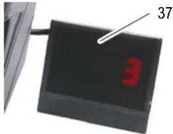
37 External display
Switching the Bank Note Counter On/Off
The bank note counter is switched on and off using a switch [8] on the rear of the machine.
After switching the bank note counter on, it completes a self-diagnosis. During the self-diagnosis, 8888 and 8888 appear in the displays [24, 30]. When the self-diagnosis has finished without any errors, 0 appears in the displays [24, 30].
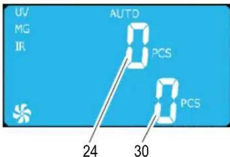
If an error is detected, it is indicated in the top display [24] (refer to Clearing Errors).
Validation Tests
Selecting the Features to be Tested
Before inserting the bank notes, select the sensors which should be active to test the respective feature (UV, MG, MT, IR).
Press the CF button [13].
The bank note counter switches to the selection mode for features to be tested, as described below. When this mode is active, the digit keys cannot be used to enter numbers.
Press the CF button [13] again to end the selection of features for testing and switch back to digit entry.
Detecting UV Features on Bank Notes:
Press the UV button [15].
The ultraviolet sensor for detecting UV features is activated/deactivated. UV [36] appears in the display.
Detecting the Magnetic Features on the Bank Notes:
Press the MG button [14].
The magnet sensor used to detect the magnetic features is activated/deactivated. MG [35] appears in the display.
Detecting the Advanced Magnetic Features on the Bank Notes:
Press the MT button [23].
The magnet sensor used to detect the advanced magnetic features is activated/deactivated. MT [32] appears in the display.
Detecting the Bank Note Width:
Press the DD button [20].
The sensor for detecting the width of the bank notes is activated/deactivated. DD [33] appears in the display.
Detecting Double Bank Notes
i The infrared sensor should always be active when testing bank notes.
Press the IR button [16].
The infrared sensor for detecting double bank notes is activated/deactivated. IR [34] appears in the display.
Preparing Bank Notes
i The best results are achieved after a warm-up phase of 3 minutes.
Bright ambient light can affect the sensor and falsify results.
Pay attention to the following points to prevent malfunctions.
A

B

C
D
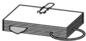
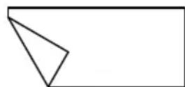
- Check the batch of bank notes for paper clippings, paper clips, rubber bands and other foreign bodies and remove them before inserting the bundle in the machine (Figure A).
Do not insert any damaged bank notes (Figure B).
Smoothen any creased and folded bank notes before inserting them (Figure C/D).
Do not insert any bank notes which are stuck together in the bank note counter.
Fan out the bank notes to separate them prior to insertion.
Inserting Bank Notes
The bank note counter is a front loading device in which the bank notes are loaded from the front.
Insert the batch of bank notes on the infeed tray [3].
The bottom note in the batch of bank notes is drawn into the bank note counter.
i Complete the count to detect critical bank notes. The verification features are tested on both sides of each bank note in one process.
Automatic/Manual Infeed
Automatic Infeed:
Press the M/A button [22].
Automatic infeed of the bank notes is activated. AUTO [25] appears in the display.
Manual Infeed:
Press the M/A button [22] until AUTO [25] disappears from the display.
Manual infeed of the bank notes is activated.
Press the RESET button [18] to start counting.
Functions
Select the required function.
Counting
This function counts the number of bank notes and depending on the sensor setting, their validity.
During the counting process, the quantity of bank notes appears in the top display [24].
If the bank notes counted are left in the output tray [6], counting resumes from the last number.
If the bank notes counted are removed from the output tray [6] and a new batch of bank notes is placed in the infeed tray [3], counting begins from .
The previous count for the bank notes appears in the bottom display [30].
Press the COUNT button [17].
The bank notes are counted without any verification tests (UV, MG, MT, IR) and discharged in the output tray [6].
Adding
When this function is activated, counting is continued even if the bank notes counted are removed from the output tray [6] and a new bundle of bank notes is laid in the infeed tray [3].
This function is particularly useful in the case of large batches of bank notes and for heavily used and creased bank notes. Smaller batches of bank notes can then be counted in succession. The bank note counter continues with the count of the bank notes.
Press the ADD button [19].
The Add function is activated/deactivated.
ADD [28] appears in the display.
Batch
This function causes counting to stop when a preset quantity of bank notes has been counted. If the batch of bank notes counted is removed from output tray [6], the top display [24] skips back to and the next batch of bank notes is counted.
Press the BATCH/C button [21].
BAT [27] appears in the display. The preset number 100 appears in the bottom display [30].
Use the digit buttons to enter the quantity you want counted.
The number is freely selectable between I and 999.
The number entered appears in the bottom display [30]. The bank note counter is ready for the batch function.
Insert the batch of bank notes on the infeed tray [3].
The number of bank notes counted appears in the top display [24].
If the bank notes in the infeed tray [3] run out before the number defined is reached, the top display [24] indicates the number counted up to now. When more bank notes are then inserted in the infeed tray [3], the process is resumed until the preset number is reached.
Press the BATCH/C button [21] to deactivate the function.
Maintenance
Cleaning the Sensors
Bank notes are often soiled, particularly by dust. The dirt deposits on the sensors during the counting process. Soiled sensors are the most frequent cause of malfunctions.
Switch the bank note counter off using the switch [8].
Disconnect the power cable from the mains power socket.
Pivot the top housing cover upwards.
Clean areas which cannot be accessed using compressed air, if necessary. Compressed air can be obtained in small aerosol cans.
Clean the sensors with the brush supplied.
Pivot the top cover back down.
Adjusting the Pressure of the Infeed Rollers
The bank note counter is set-up at the factory to draw the bank notes in properly. If the bank notes are no longer drawn in properly or the EES alarm indicator appears in the display [2], you must change the pressure applied by the infeed rollers.
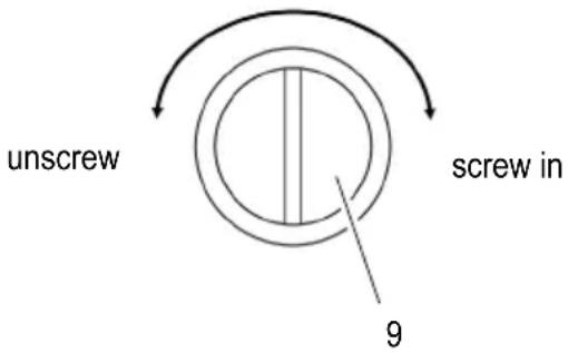
The adjusting screw [9] to alter the pressure exerted by the infeed rollers is located at the rear.
Turning the adjusting screw [9] counterclockwise reduces the pressure applied by the infeed rollers.
Turning the adjusting screw [9] clockwise increases the pressure applied by the infeed rollers.
Switch the bank note counter off using the switch [8].
Disconnect the power cable from the mains power socket.
Adjust the pressure of the infeed rollers with the adjusting screw [9] so that the bank notes can slide under the infeed rollers with a little force.
Clearing Errors
Error Indicators
Errors are indicated in the top display line [24] by means of code numbers. At the same time, the display [2] is switched to a red background.
A frequent source of errors is soiling of the sensors (see Cleaning the Sensors). Following the instructions provided under "Solution".
| Code No. | Cause Solution | |
| EO1 | The left-hand sensor for counting the bank notes is soiled or damaged. | Clean the sensor. If the error continues to occur, refer to the information in Chapter "Warranty". |
| EO2 | The right-hand sensor for counting the bank notes is soiled or damaged. | |
| EO3 | The code disk is soiled, loose or damaged. | Refer to the information in Chapter "Warranty". |
| EO4 | The sensor in the infeed tray [3] is soiled or damaged. | Clean the sensor. If the error continues to occur, refer to the information in Chapter "Warranty". |
| EO5 | The sensor in the output tray [6] is soiled or damaged. | |
| EORThe ambient light is too bright or contains UV components. | Dim the ambient light or switch off the ambient light. | |
| bF | The infeed rollers rotate but do not draw any bank notes in. | Press the RESET button [18] and repeat the counting function. If the error continues to occur, refer to the information in Chapter "Adjusting the Pressure of the Infeed Rollers". |
Alarm Indicators
Alarms are indicated in the top display line [24] by means of code numbers. At the same time, the display is switched to a red background.
| Code No. | Cause Solution | |
| EE1 | Critical bank notes were detected by the UV sensor. Too little or no ultraviolet reaction from the bank note. | Remove the critical bank note from the output tray [6]. Press the RESET button [18] to continue counting. |
| EE2 | Critical bank note has been detected. Too little or no magnetic reaction from the bank note. | |
| EE4 | Bank note was detected as a half bank note. | Remove the critical bank note from the output tray [6] and check the bank notes for signs of damage. Press the RESET button [18] to continue counting. |
| EE5 | Doubled bank notes have been detected. | Adjust the pressure exerted by the infeed rollers. Check whether the bank notes have stuck together. Start the counting function again. |
| EE6 | Critical bank note detected by the MT sensor. Banknote with abnormal magnetism has been detected. | Remove the critical bank note from the output tray [6]. Press the RESET button [18] to continue counting. |
| EE7 | Bank note drawn in at an angle. Lay the bank note in the infeed tray [3] again. Press the RESET button [18] to continue counting. | |
| EE8 | Bank note smaller than default value has been detected. | Remove the critical bank note from the output tray [6]. Press the RESET button [18] to continue counting. |
| EE9 | Bank note larger than default value has been detected. | |
| EEH | Doubled or chained bank notes detected. | |
| EEb | Width difference between the last bank note and the first bank note counted is more than the default value. | |
Technical Data
| Model NC 455 | |
| Functions Free counting mode (without validation test)Automatic and manual startBatch function, up to 999 bank notes can be selectedAdd function | |
| Validation test Test of ultraviolet and magnetic featuresUV, IR and magnetic sensors can be deactivated | |
| Capacities: infeed and output trays | 200 older bank notes300 new bank notes |
| Size of countable bank notes 50 mm × 110 mm bis 85 mm × 180 mm | |
| Thickness of countable bank notes | 0.075 – 0.15 mm |
| Counting range | 1 – 9999 |
| Counting speed 1,000 bank notes / minute | / minute |
| Power supply 230 V (AC), 50 Hz | |
| Power consumption 90 W | |
| Fuse 3.15 A / 250 V | |
| Volume 60 dB | |
| Temperature (operation): | 0 °C – 40 °C |
| Rel. humidity (operation): | 60 – 90 % |
| Dimensions 242 mm × 276 mm × 245 mm | |
| Weight 4.7 kg | |
Care Instructions
Clean the housing surface with a soft, lint-free cloth.
Clean the sensors with the brush supplied each time after use.
Do not use any solvents or cleaning agents.
Disposal

In order to dispose of your device, take it to a collection point provided by your local public waste authorities (e.g. recycling centre).
According to laws on the disposal of electronic and electrical devices, owners are obliged to dispose of old electronic and electrical devices in a separate waste container. The adjacent symbol indicates that the device must not be disposed of in normal domestic waste!
Packaging materials must be disposed of according to local regulations.
Warranty
Dear customer,
we are delighted that you have chosen this equipment.
In the case of a defect, please return the device together with the receipt and original packing material to the point of sale.
FRANÇAIS
Mode d'emploi

GBIE CY Declaration of conformity
To view the complete Declaration of Conformity, please refer to the free download available on our website www.go-europe.com.
GB IE CY All rights reserved.

- Service-Center Hattingen
- Safety Instructions
- WARNING!
- CAUTION!
- ATTENTION!
- Intended Use
- Scope of Delivery
- Display and Notation
- Operating Elements
- Keypad
- Display
- Operation
- Connecting the Bank Note Counter
- Connecting an External Display
- External display
- Switching the Bank Note Counter On/Off
- Validation Tests
- Selecting the Features to be Tested
- Detecting UV Features on Bank Notes:
- Detecting the Magnetic Features on the Bank Notes:
- Detecting the Advanced Magnetic Features on the Bank Notes:
- Detecting the Bank Note Width:
- Detecting Double Bank Notes
- Preparing Bank Notes
- Inserting Bank Notes
- Automatic/Manual Infeed
- Automatic Infeed:
- Manual Infeed:
- Functions
- Counting
- Adding
- Batch
- Maintenance
- Cleaning the Sensors
- Adjusting the Pressure of the Infeed Rollers
- Clearing Errors
- Error Indicators
- Alarm Indicators
- Technical Data
- Care Instructions
- Disposal
- Warranty
- FRANÇAIS
- Mode d'emploi
- GBIE CY Declaration of conformity
Brand : OLYMPIA
Model : NC 455
Category : Coin and bill counter