EMS305RG - Electric saw RYOBI - Free user manual and instructions
Find the device manual for free EMS305RG RYOBI in PDF.
| Product Type | Compound Miter Saw |
| Brand | RYOBI |
| Model | EMS305RG |
| Intended Use | Sawing solid wood, particleboard, similar materials, plastics |
| Blade Diameter | 305 mm |
| Blade Bore | 30 mm |
| Power | 1800 W |
| Power Supply | 230 V ~ 50 Hz |
| Weight | 17 kg |
| Dimensions (L x W x H) | 580 x 420 x 420 mm |
| Cutting Capacity at 0° | 100 x 305 mm |
| Bevel Cutting Capacity | 90 x 305 mm |
| Miter Angle Range | 0° – 45° left and right |
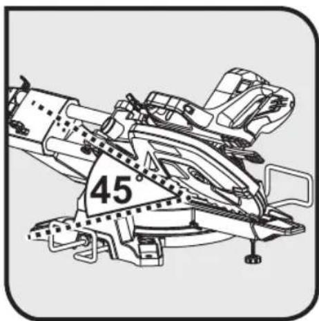
| Bevel Angle Range | 0° – 45° left |
| No-Load Speed | 3800 rpm |
| Laser Guide | Class 2, ≤1 mW, 650 nm |
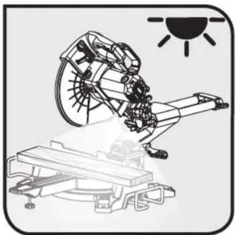
| LED Lighting | Yes |
| Dust Extraction System | Dust bag included |
| Clamp | Yes, integrated |
| Table Extensions | Extension bars included |
| Maintenance | Regular cleaning, brush replacement by approved service center |
| Warranty | 24 months (extension possible under conditions) |
| Standards | CE, EN 62841-1, EN 62841-3-9 |
Frequently Asked Questions - EMS305RG RYOBI
User questions about EMS305RG RYOBI
0 question about this device. Answer the ones you know or ask your own.
Ask a new question about this device
Download the instructions for your Electric saw in PDF format for free! Find your manual EMS305RG - RYOBI and take your electronic device back in hand. On this page are published all the documents necessary for the use of your device. EMS305RG by RYOBI.
USER MANUAL EMS305RG RYOBI
natural_image
Exterior view of a Ryobi cutting machine with laser and blade components (no text or symbols visible)

| Important! | It is essential that you read the instructions in this manual before assembling, maintaining and operating the product. |
| Attention! | Il est essentiel que vous lisiez les instructions contenues dans ce manuel avant d'assembler, d'entretenir et d'utiliser le produit. |
| Achtung! | Es ist wichtig, dass Sie vor Zusammenbau, Wartung und Benutzung des Produktes die Anweisungen in dieser Anleitung lesen. |
| ¡Atención! | Resulta fundamental que lea este manual de instrucciones antes de realizar el montaje, el mantenimiento y de utilizar este producto |
| Attenzione! | E’ importante leggere le istruzioni contenute nel presente manuale prima di montare il prodotto, svolgere le operazioni di manutenzione sullo stesso e metterlo in funzione. |
| Let op! | Het is van essentieel belang dat u de instructies in deze gebruiksaanwijzing leest voor u het product monteert, onderhoudt en gebruikt. |
| Atenção! | É fundamental que leia as instruções deste manual antes da montagem, manutenção e operação do aparelho. |
| OBS! | Det er vigtigt, at man læser instrukserne i denne brugsanvisning, inden man samler, vedligeholder og betjener produktet. |
| Observera! | Det är viktigt att du läser instruktionerna i manualen före montering, användning och underhåll av produkten. |
| Huomio! | On tärkeää, että luet tämän käsikirjan ohjeet ennen tuotteen kokoamista, huoltoa ja käyttöä. |
| Advarse! | Det er viktig at du leser instruksjonene i denne manualen før sammensetning, vedlikehold og bruk av produktet |
| Внимание! | Необходимо прочитать инструкции в данном руководстве перед сборкой, обслуживанием и эксплуатацией этого изделия. |
| Uwaga! | Koniecznie należy przeczytać instrukcje zawarte w tym podręczniku przed montażem, obsługą oraz konserwacją produktu. |
| Dûležité upozornění! | Neinstalujte, neprovádějte údržbu ani nepoužívejte tento výrobek dřive, než si přečtete pokyny uvedené v tomto návodu. |
| Figyelem! | Fontos, hogy a termék összeszerelése, karbantartása és használata előtt elolvassa a kézikönyvben található utasításokat. |
| Atenție! | Este esențial să citiți instrucțiunile din acest manual înainte de asamblare, efectuarea întreținerii și operarea produsului. |
| Uzmanību! | Ir svarīgi izlasīt šīs rokasgrāmatas instrukcijas pirms uzstādīšanas, apkopes un preces darbināšanas. |
| Dèmesio! | Prieš surenkant, prižiūrint ir naudojant gaminį, būtina perskaityti šiame vadove pateiktus nurodymus. |
| Tähtis! | Enne masina kokkupanekut, hooldamist ja kasutama hakkamist tuleb käesolevas juhendis esitatud juhised kindlasti läbi lugeda. |
| Upozorenje! | Vrlo je važno da ste prije sklapanja, održavanja i rada s ovim proizvodom pročitali upute u ovom priručniku. |
| Pomembno! | Pomembno je da pred montažo vzdrževanjem in uporabo tega izdelka preberete navodila v tem priročniku. |
| Upzornenie! | Je dôležité, aby ste si pred montážou, údržbou a obsluhou produktu prečitali pokyny v tomto návode. |
| Bажно! | Изключително важно е да прочетете инструкциите в настоящото ръководство, преди да преминете към сглобяване, поддръжка или работа с продукта. |
| Bажливо! | Дуже важливо, щоб ви прочитали інструкції в цьому керівництві перед складанням, обслуговуванням та експлуатацією цієї машини. |
| Dikkat! | Ürünün montajını, bakımını yapmadan ve ürünü çalıştırmadan önce bu kılavuzda yer alan talimatları okumanız önemlidir. |
| Проσοχή! | Είναι πολύ σημαντικό να διαβάσετε τις οδηγίες στο παρόν εγχειρίδιο πριν συναρμολογήσετε, συντηρήσετε ή λειτουργήσετε το προϊόν. |
Subject to technical modification | Sous réserve de modifications techniques | Technische Änderungen vorbehalten | Bajo reserva de modificaciones técnicas | Con riserva di eventuali modifiche tecniche | Technische wijzigingen voorbehouden | Com reserva de modificações técnicas | Med forbehold for tekniske ændringer | Med förbehåll för tekniska ändringar | Tekniset muutokset varataan | Med forbehold om tekniske endringer | могут быть внесены технические изменения | Z zastrzeżeniem modyfikacji technicznych | Změny technických údajů vyhrazeny | A můszaki módosítás jogát fenntartjuk | Sub rezerva modificațiilor tehnice | Paturam tiesības mainīt tehniskos raksturlielumus | Pasiliekant teisę daryti techninius pakeitimus | Tehnilised muudatused võimalikud | Podloæno tehniëkim promjenama | Tehnične spremembe dopuščene | Právo na technické zmeny je vyhradenė | Подлежи на технически модификации | Є об'єктом для технічних змін | Teknik değişiklik hakki saklıdır | Упó тнү επιφύλαξη τεχνικών τροποποιήσεων

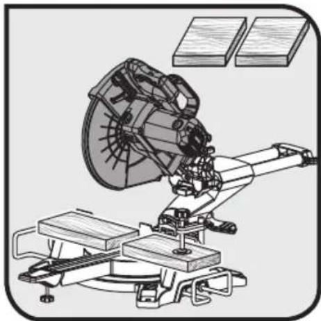
Safety, performance, and dependability have been given top priority in the design of your mitre saw.
INTENDED USE
The mitre saw is intended for sawing solid and bonded wood, materials similar to wood, with or without glued veneer and plastics.
The mitre saw is intended to be used only by adult operators who have read the instruction manual and understand the risks and hazards.
The mitre saw is designed to be fixed at solid bench top. If the base is not securely whole machine may move during cutting operations, which increases the possibility of serious personal injury.
The mitre saw is designed to make bevel and mitre cuts. The capacities for the various cuts are provided in the product specifications in this manual.
The mitre saw is to be used in dry conditions, with excellent ambient lighting and adequate ventilation.
The mitre saw is intended for consumer use and should only be used as described above and is not intended for any other purpose.
GENERAL POWER TOOL SAFETY WARNINGS
WARNING
Read all safety warnings, instructions, illustrations and specifications provided with this power tool. Failure to follow all instructions listed below may result in electric shock, fire and/or serious injury.
Save all warnings and instructions for future reference. The term "power tool" in the warnings refers to your mains-operated (corded) power tool or battery-operated (cordless) power tool.
WORK AREA SAFETY
- Keep work area clean and well lit. Cluttered or dark areas invite accidents.
- Do not operate power tools in explosive atmospheres, such as in the presence of flammable liquids, gases or dust. Power tools create sparks which may ignite the dust or fumes.
- Keep children and bystanders away while operating a power tool. Distractions can cause you to lose control.
ELECTRICAL SAFETY
■ Power tool plugs must match the outlet. Never modify the plug in any way. Do not use any adapter plugs with earthed (grounded) power tools. Unmodified plugs and matching outlets will reduce risk of electric shock.
■ Avoid body contact with earthed or grounded
surfaces, such as pipes, radiators, ranges and refrigerators. There is an increased risk of electric shock if your body is earthed or grounded.
- Do not expose power tools to rain or wet conditions. Water entering a power tool will increase the risk of electric shock.
- Do not abuse the cord. Never use the cord for carrying, pulling or unplugging the power tool. Keep cord away from heat, oil, sharp edges or moving parts. Damaged or entangled cords increase the risk of electric shock.
the When operating a power tool outdoors, use an fixed extension cord suitable for outdoor use. Use of a cord suitable for outdoor use reduces the risk of electric shock.
If operating a power tool in a damp location is unavoidable, use a residual current device (RCD) protected supply. Use of an RCD reduces the risk of electric shock.
PERSONAL SAFETY
■ Stay alert, watch what you are doing and use common sense when operating a power tool. Do not use a power tool while you are tired or under the influence of drugs, alcohol or medication. A moment of inattention while operating power tools may result in serious personal injury.
■ Use personal protective equipment. Always wear eye protection. Protective equipment such as a dust mask, non-skid safety shoes, hard hat, or hearing protection used for appropriate conditions will reduce personal injuries.
■ Prevent unintentional starting. Ensure the switch is in the off -position before connecting to power source and/or battery pack, picking up or carrying the tool. Carrying power tools with your finger on the switch or energising power tools that have the switch on invites accidents.
■ Remove any adjusting key or wrench before turning the power tool on. A wrench or a key left attached to a rotating part of the power tool may result in personal injury.
- Do not overreach. Keep proper footing and balance at all times. This enables better control of the power tool in unexpected situations.
■ Dress properly. Do not wear loose clothing or jewellery. Keep your hair and clothing away from moving parts. Loose clothes, jewellery or long hair can be caught in moving parts.
If devices are provided for the connection of dust extraction and collection facilities, ensure these are connected and properly used. Use of dust collection can reduce dust-related hazards.
- Do not let familiarity gained from frequent use of tools allow you to become complacent and ignore tool safety principles. A careless action can cause severe injury within a fraction of a second.
POWER TOOL USE AND CARE
- Do not force the power tool. Use the correct power tool for your application. The correct power tool will do the job better and safer at the rate for which it was designed.
- Do not use the power tool if the switch does not turn it on and off. Any power tool that cannot be controlled with the switch is dangerous and must be repaired.
- Disconnect the plug from the power source and/or remove the battery pack, if detachable, from the power tool before making any adjustments, changing accessories, or storing power tools. Such preventive safety measures reduce the risk of starting the power tool accidentally.
■ Store idle power tools out of the reach of children and do not allow persons unfamiliar with the power tool or these instructions to operate the power tool. Power tools are dangerous in the hands of untrained users. - Maintain power tools and accessories. Check for misalignment or binding of moving parts, breakage of parts and any other condition that may affect the power tool's operation. If damaged, have the power tool repaired before use. Many accidents are caused by poorly maintained power tools.
- Keep cutting tools sharp and clean. Properly maintained cutting tools with sharp cutting edges are less likely to bind and are easier to control.
- Use the power tool, accessories and tool bits etc. in accordance with these instructions, taking into account the working conditions and the work to be performed. Use of the power tool for operations different from those intended could result in a hazardous situation.
- Keep handles and grasping surfaces dry, clean and free from oil and grease. Slippery handles and grasping surfaces do not allow for safe handling and control of the tool in unexpected situations.
SERVICE
- Have your power tool serviced by a qualified repair person using only identical replacement parts. This will ensure that the safety of the power tool is maintained.
SAFETY INSTRUCTIONS FOR MITRE SAWS
- Mitre saws are intended to cut wood or wood-like products, they cannot be used with abrasive cut-off wheels for cutting ferrous material such as bars, rods, studs, etc. Abrasive dust causes moving parts such as the lower guard to jam. Sparks from abrasive cutting will burn the lower guard, the kerf insert and other plastic parts.
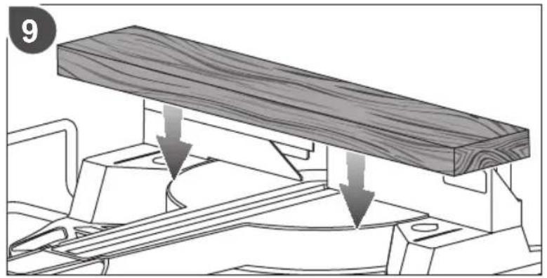
■ Use clamps to support the workpiece whenever possible. If supporting the workpiece by hand, you must always keep your hand at least 100 mm from either side of the saw blade. Do not use this saw to
cut pieces that are too small to be securely clamped or held by hand. If your hand is placed too close to the saw blade, there is an increased risk of injury from blade contact.
The workpiece must be stationary and clamped or held against both the fence and the table. Do not feed the workpiece into the blade or cut "freehand" in any way. Unrestrained or moving workpieces could be thrown at high speeds, causing injury.
■ Push the saw through the workpiece. Do not pull the saw through the workpiece. To make a cut, raise the saw head and pull it out over the workpiece without cutting, start the motor, press the saw head down and push the saw through the workpiece. Cutting on the pull stroke is likely to cause the saw blade to climb on top of the workpiece and violently throw the blade assembly towards the operator.
- Never cross your hand over the intended line of cutting either in front or behind the saw blade. Supporting the workpiece "cross handed" i.e. holding the workpiece to the right of the saw blade with your left hand or vice versa is very dangerous.
- Do not reach behind the fence with either hand closer than 100 mm from either side of the saw blade, to remove wood scraps, or for any other reason while the blade is spinning. The proximity of the spinning saw blade to your hand may not be obvious and you may be seriously injured.
- Inspect your workpiece before cutting. If the workpiece is bowed or warped, clamp it with the outside bowed face toward the fence. Always make certain that there is no gap between the workpiece, fence and table along the line of the cut. Bent or warped workpieces can twist or shift and may cause binding on the spinning saw blade while cutting. There should be no nails or foreign objects in the workpiece.
- Do not use the saw until the table is clear of all tools, wood scraps, etc., except for the workpiece. Small debris or loose pieces of wood or other objects that contact the revolving blade can be thrown with high speed.
- Cut only one workpiece at a time. Stacked multiple workpieces cannot be adequately clamped or braced and may bind on the blade or shift during cutting.
■ Ensure the mitre saw is mounted or placed on a level, firm work surface before use. A level and firm work surface reduces the risk of the mitre saw becoming unstable.
Plan your work. Every time you change the bevel or mitre angle setting, make sure the adjustable fence is set correctly to support the workpiece and will not interfere with the blade or the guarding system. Without turning the tool "ON" and with no workpiece on the table, move the saw blade through a complete simulated cut to assure there will be no interference or danger of cutting the fence.
■ Provide adequate support such as table extensions, saw horses, etc. for a workpiece that is wider or
longer than the table top. Workpieces longer or wider than the mitre saw table can tip if not securely supported. If the cut-off piece or workpiece tips, it can lift the lower guard or be thrown by the spinning blade.
- Do not use another person as a substitute for a table extension or as additional support. Unstable support for the workpiece can cause the blade to bind or the workpiece to shift during the cutting operation pulling you and the helper into the spinning blade.
■ The cut-off piece must not be jammed or pressed by any means against the spinning saw blade. If confined, i.e. using length stops, the cut-off piece could get wedged against the blade and thrown violently.
■ Always use a clamp or a fixture designed to properly support round material such as rods or tubing. Rods have a tendency to roll while being cut, causing the blade to "bite" and pull the work with your hand into the blade. - Let the blade reach full speed before contacting the workpiece. This will reduce the risk of the workpiece being thrown.
If the workpiece or blade becomes jammed, turn the mitre saw off. Wait for all moving parts to stop and disconnect the plug from the power source and/or remove the battery pack. Then work to free the jammed material. Continued sawing with a jammed workpiece could cause loss of control or damage to the mitre saw.
■ After finishing the cut, release the switch, hold the saw head down and wait for the blade to stop before removing the cut-off piece. Reaching with your hand near the coasting blade is dangerous. - Hold the handle firmly when making an incomplete cut or when releasing the switch before the saw head is completely in the down position. The braking action of the saw may cause the saw head to be suddenly pulled downward, causing a risk of injury.
SAFETY INSTRUCTIONS FOR WOOD CUTTING BLADE
■ Please read the manual and instructions carefully before using the saw blade and the machine.
■ The product must be in good condition, the spindle without deformation and vibration.
- Do not use the product without the guards in position. Keep guards in good working order and properly maintained.
■ Ensure the operator is adequately trained in safety precautions, adjustment and operation of the product.
■ Always wear goggles and ear protection when using the product. It is recommended to wear gloves, sturdy non slipping shoes and apron.
■ Before using any accessory, consult the instruction manual. The improper use of an accessory can cause damage and increase the potential for injury.
■ Use only blades specified in this manual, complying
with EN 847-1.
- Observe the maximum speed marked on the saw blade. Ensure the speed marked on the saw blade is at least equal to the speed marked on the saw.
■ Always use blades with correct size and shape of arbour holes. Blades that do not match the mounting hardware of the saw will run eccentrically, causing loss of control. - Do not use blades of larger or smaller diameter than recommended. Do not use any spacers to make the blade fit onto the spindle.
- Check the tips of the saw blade for damage or abnormal appearance before each use. Tips that are damaged or loose can become flying objects in use and increase the chance of personal injury.
■ Do not use cracked or distorted saw blades. Do not use saw blades that are damaged or deformed. - Scrap the saw blade if damaged, deformed, distorted or cracked, repairing is not permitted.
■ Do not use HSS blades.
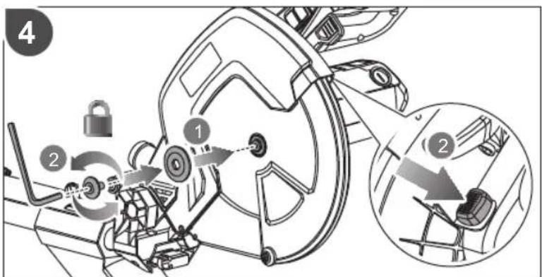
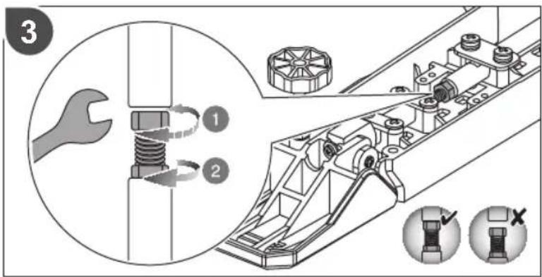
■ Ensure the saw blade is mounted correctly, tighten the arbor nut securely before use (tightening torque approx. 12-15 Nm).
■ Fastening screw and nuts shall be tightened using the appropriate spanner, etc.
■ Extension of the spanner or tightening using hammer blows is not permitted.
■ Make sure the blade and flanges are clean and the recessed sides of the collar are against the blade.
■ Make sure the blade rotates in the correct direction.
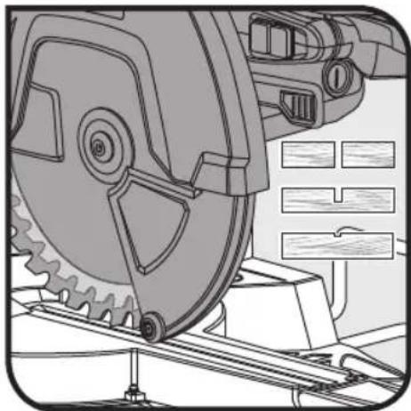
■ Before work, make a dummy cut without the motor turned on so the position of the blade, operation of the guards with respect to other machine parts and workpiece may be checked.
■ Never leave the product unattended.
■ Do not apply lubricants on the blade when it is running.
■ Never perform any cleaning or maintenance work when the machine is still running and the head is not in the rest position.
■ Never attempt to stop a machine in motion rapidly by jamming a tool or other means against the blade, serious accidents can be caused unintentionally in this way.
■ Disconnect the product from the mains supply or remove battery pack before changing blades or carrying out maintenance.
■ Pay attention to blade packing and unpacking, it is easy to be injured by the sharp blade tips.
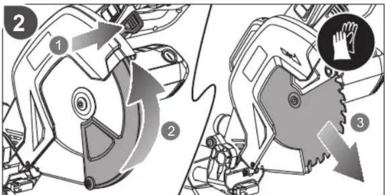
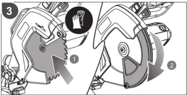
■ Use a blade holder or wear gloves when handling a saw blade. - Keep and store the blade in original packaging or other suitable packaging, keep in dry conditions and away from chemicals which may damage the blade.
ADDITIONAL SAFETY WARNINGS
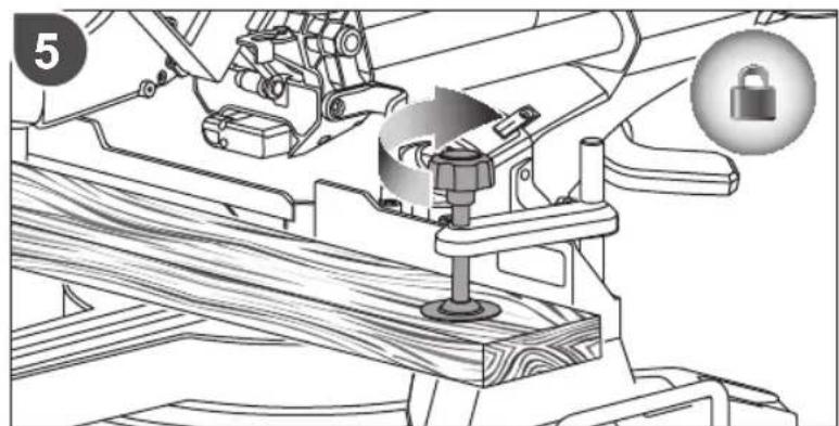
■ Always clamp the workpiece safely and securely.
■ Ensure that the product is always stable and secure (e.g., fixed to a bench).
■ Always wear ear protectors. Exposure to noise can cause hearing loss.
■ Always wear safety goggles when using the product. It is recommended to wear gloves for handling blades and rough material, plus sturdy non slip shoes to protect the feet from workpieces which may fall from the cutting area.
■ Disconnect the product from the mains supply or remove battery pack before carrying out any maintenance or cleaning the product.
■ Only connect to the mains supply when the product is switched off.
- Keep the mains lead clear from the working range of the machine. Keep it out of the area the operator stands in.
■ Never reach into the area near the blade unless the blade has completely stopped.
■ Before use, thoroughly check the product, cable, and plug for any damage or material fatigue. Repairs to the whole machine, including the power cable should only be carried out by authorised service agents.
■ Always use the guards on the product. Do not use the product if the guards are not in place and working correctly.
- The lower blade guard should only open when the blade is lowered to the workpiece and must always be able to move freely and close automatically.
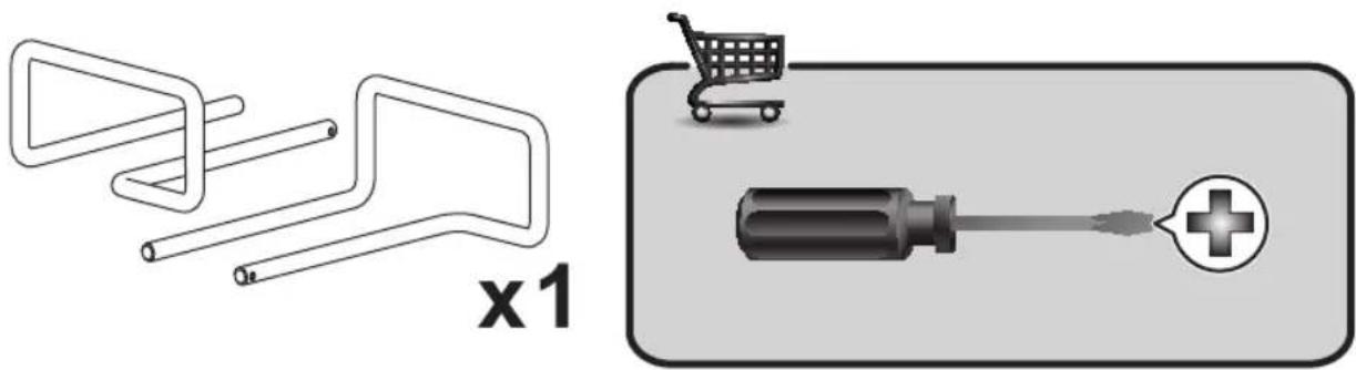
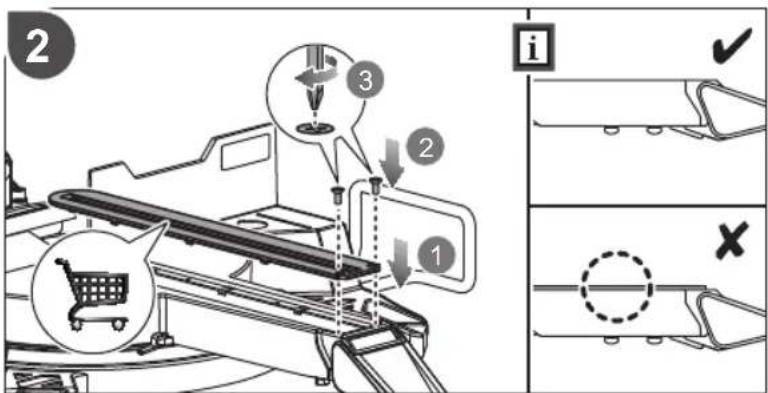
■ Always fix and use extension bars for workpiece support during operation.
■ Never alter of modify the product or its function. Your safety may be compromised.
■ Do not use saw blades which are cracked, damaged or deformed.
■ Do not use saw blades made of high-speed steel.
■ Only use blades that are sharp. Replace dull blades.
■ Always use blades with correct size and shape of arbour holes. Blades that do not match the mounting hardware of the saw will run eccentrically, causing loss of control.
■ Use only woodworking blades specified in this manual, which comply with EN 847-1.
- Do not use any flanges, washers and nuts to secure the saw blade other than those supplied or indicated in the instruction manual.
It is necessary to select a saw blade which is suitable for the material being cut. Never use the product to cut materials other than those specified in the intended use section in this manual.
■ It is important to avoid overheating the blade and
melting the plastic when cutting.
It is essential to adhere to the maximum speed specified on the saw blade, only use saw blade that are marked with a speed equal or higher than the speed marked on the tool.
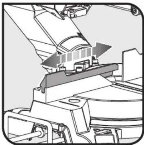
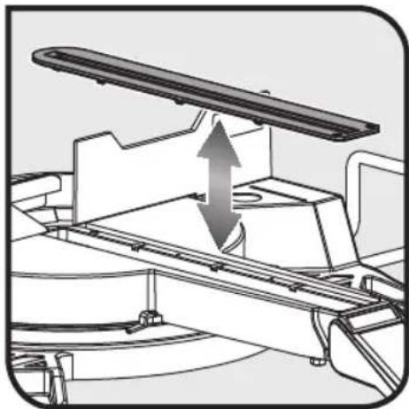
■ Replace the table insert when worn or damaged.
■ Before work, make a dummy cut without the motor turned on so the position of the blade, operation of the guards with respect to other machine parts, and workpiece may be checked.
■ When performing mitre, bevel or compound mitre cuts, adjust the sliding fence or sub-fence to ensure the correct clearance from the blade.
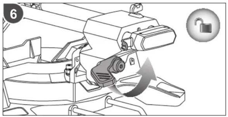
■ The handle lock must always be engaged when transporting the product.
- Keep the floor area free of loose materials, such as chips and cut-offs.
■ Refrain from removing any cut-offs or other parts of the workpiece from the cutting area whilst the product is running and the saw head is not in the rest position.
■ Long workpieces must be adequately supported. The working area of the saw includes the whole extent of the workpiece. The operator should secure this area from accidental contact from other persons or objects which may move the workpiece during operation.
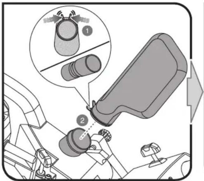
■ The dust produced when using the product may be harmful to health. Use a dust suction system and wear a suitable dust protection mask. Remove deposited dust thoroughly with a vacuum cleaner.
- Do not replace the laser or LED with a different type. Any repairs must only be carried out by the manufacturer or authorised service agent.
■ The unit should be connected to a power circuit protection device (fuse or circuit breaker).
■ When using the mitre saw outdoors, the manufacturer recommends the use of an RCD device with a trip set at 30mA.
- When using this tool, voltage fluctuations may affect other electrical products or lighting on the same power circuit. Connect the tool to a power source with an impedance equal to 0.071 Ω to minimise fluctuations. Contact your electric power supplier for further clarification.
voltage
LASER SAFETY RULES
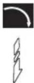
■ The laser radiation used in this saw is Class 2 with maximum ≤1mW and 650nm wavelengths. Do not stare into the laser beam. Failure to comply with the rules could result in serious personal injury.
■ Do not stare into beam during operation.
■ Do not project the laser beam directly into the eyes of others. Serious eye injury could result.
■ Do not place the laser in a position that may cause anyone to stare into the laser beam intentionally or unintentionally.
■ Do not use optical tools to view the laser beam.
■ Do not operate the laser around children or allow children to operate the laser.
■ Do not attempt to repair the laser device by yourself.
■ Do not attempt to change any parts of the laser device by yourself.
■ Any repairs must only be carried out by the laser manufacturer or authorised service agent.
■ Do not replace the laser with a different type.
RESIDUAL RISKS
Even when the product is used as prescribed, it is still impossible to completely eliminate certain residual risk factors. The following hazards may arise and the operator should pay special attention to avoid the following:
■ Risk of contact with uncovered parts of the rotating saw blade
■ Kick-back of workpieces or parts of workpieces due to improper adjustment or handling
■ Catapulting of faulty carbide tips from the saw blade
■ Damage to the respiratory system
NOTE: Wear respiratory protection masks containing filters appropriate to the materials being worked. Ensure adequate workplace ventilation. Do not eat, drink or smoke in the work area.
■ Damage to hearing if effective hearing protection is not worn.
WARNING
Dust from certain paints, coatings and materials may cause irritation or allergic reactions to the respiratory system. Dust from wood such as oak, beech, MDF and others are carcinogenic. Material containing asbestos should only ever be worked or processed by qualified specialist operators.
WARNING
Injuries may be caused, or aggravated, by prolonged use of a tool. When using any tool for prolonged periods, ensure you take regular breaks.
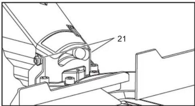
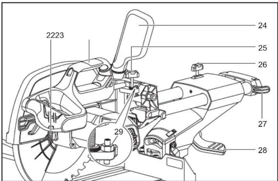
KNOW YOUR PRODUCT
See page 222 - 223.
- Handle, insulated gripping surface
- Power switch
- Safety lock handle
- Upper guard
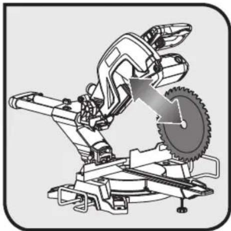
- Saw blade
- Lower guard
- Clamp
-
Main fence
-
Turntable
- Base
- Table insert
- Turntable lock handle
- Balancing foot
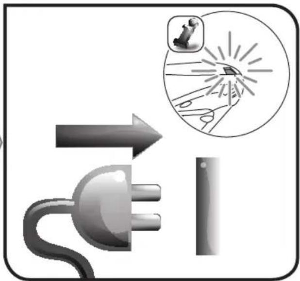
- Laser switch
- LED switch
- Bracket stop
- Lower guard cover
- Sliding fence
- Mounting hole
- Extension bar
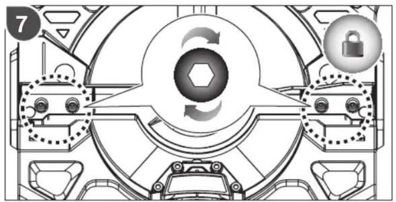
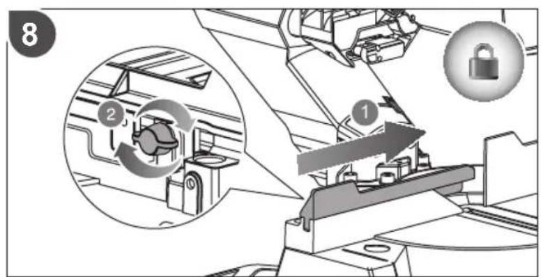
- Screws for adjusting the bevel angle limit stop
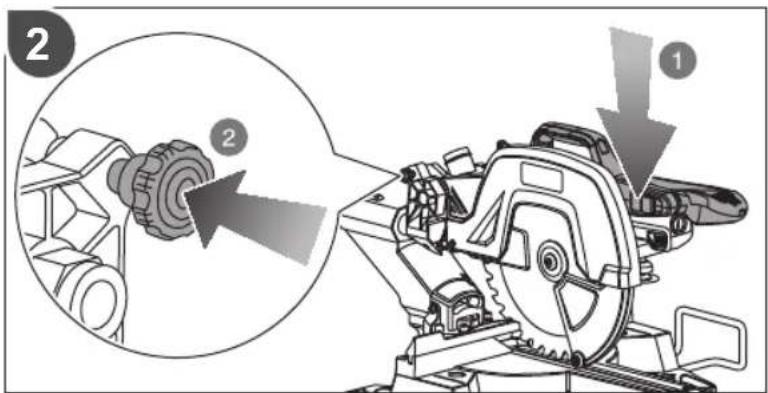
- Spindle lock knob
- Top handle
- Dust bag
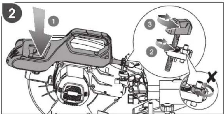
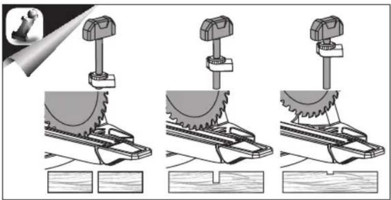
- Cutting depth adjustment knob
- Linear rod stop knob
- Winding support
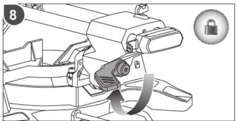
- Bevel angle lock knob
- Maximum cutting depth stop
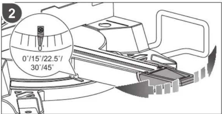
- Screws for adjusting mitre angle
OPERATION
The product features a moving saw blade that can be set at various angles by the operator when cutting a work piece which is securely fixed to the base of the product. It must be operated by only one person to prevent unintentional contact with the moving saw blade.
The principles for safe operation of the product are as follows:
■ Maintain saw, blades and work area in good condition.
- Secure the mitre saw base to a sturdy work bench. The product may move and tip if it is not adequately secured.
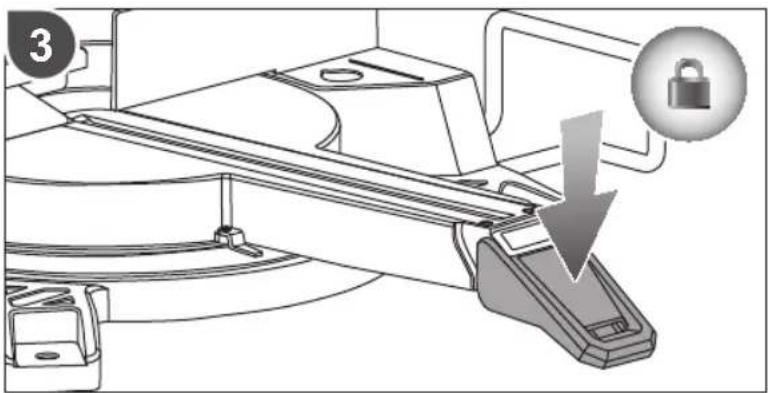
■ Set up and lock the cutting angles and depth before making the cut.
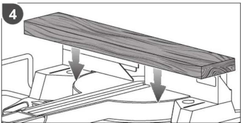
- Secure the work piece to the mitre saw base. Use the clamp provided and, where necessary, use additional clamps or holding mechanisms to prevent unintentional movement of the work piece while cutting.
- Check that the operation of the blade guards are not restricted by the position of the work piece.
- Ensure that the fence and other parts of the product will not be cut as the blade lowers to the cutting position.
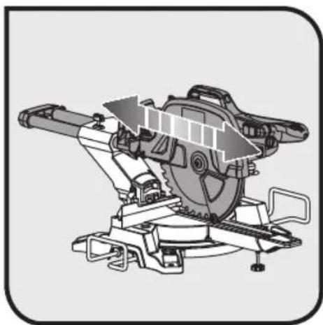
■ Start the motor and allow the blade to reach full speed before slowly lowering it to cut the work piece. Slide the blade assembly backwards and/or forwards to complete the cut as necessary.
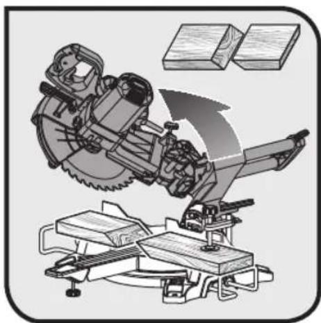
- Allow the blade assembly to rise to its upper position where the blade guards are fully closed. Switch off the motor and allow the blade to come to a complete stop before removing the work piece or off-cuts, or before reaching into the area of the blade.
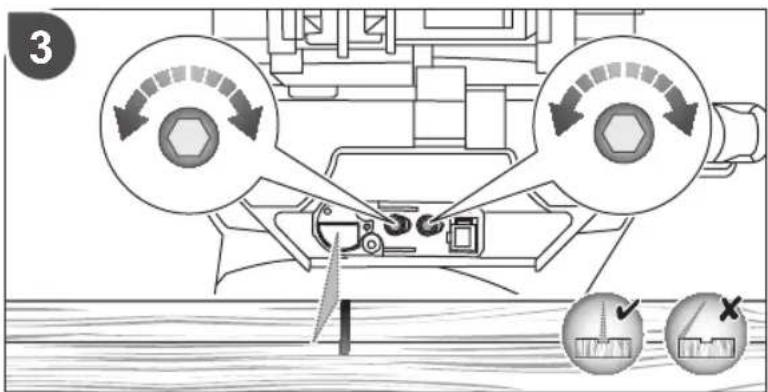
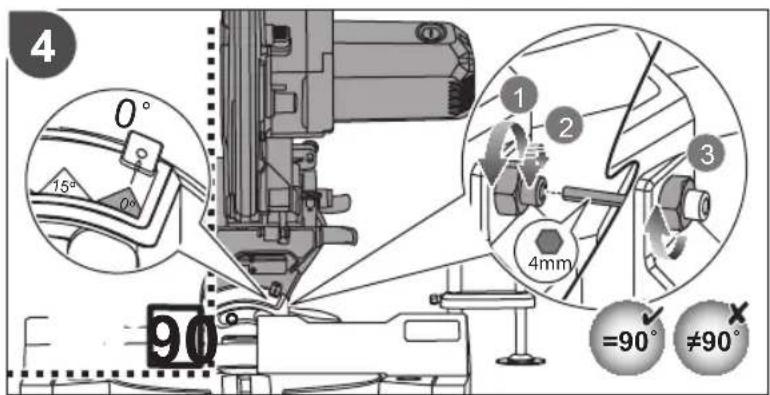
Before first use, ensure that the angle of the bevel or mitre
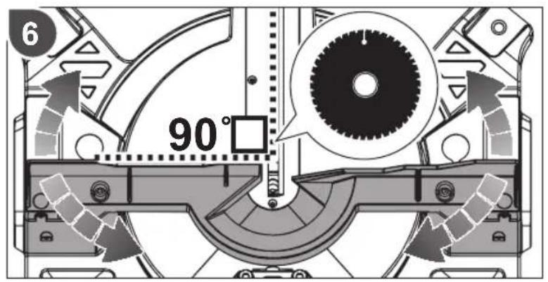
set on the product matches the angle to be produced on the work piece. Check this on a discarded piece of wood by using a carpenter's set or mitre square.
WARNING
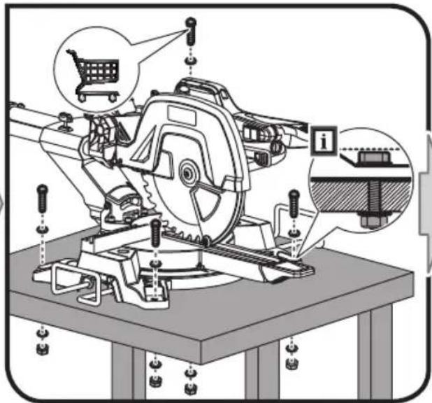
The manufacturer strongly recommends that the product is always securely mounted to a bench top.
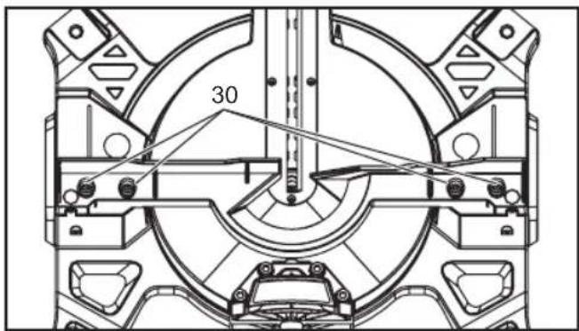
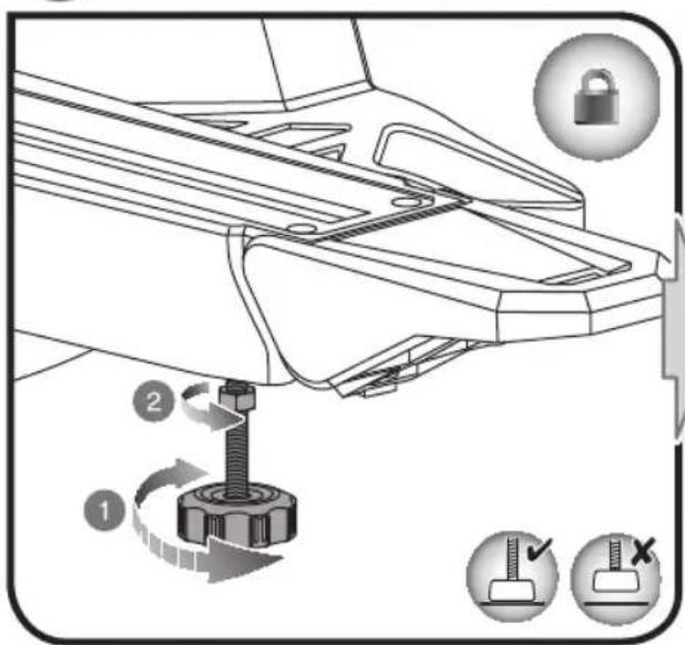
When the base of the product is firmly secured to a bench top by the four nuts, bolts and washers provided, the product can be used at maximum bevel and mitre setting without the possibility of it tipping over. If the product is not secured properly, the product may over balance when large bevel angles are selected.
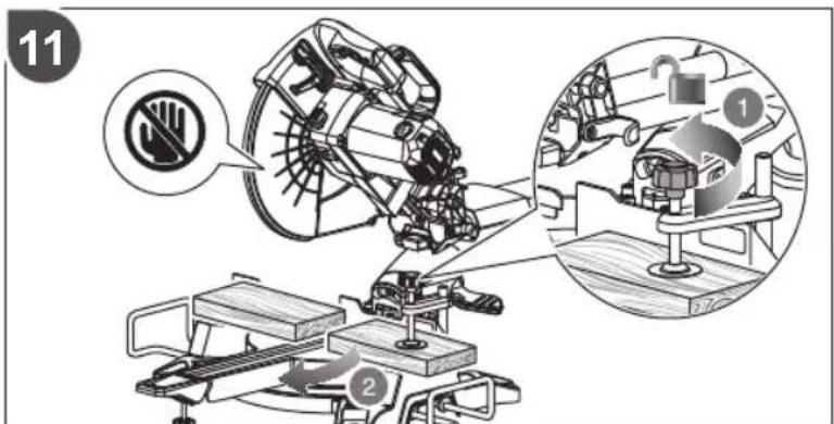
There is an adjustable screw (balancing foot) that extends from the bottom of the extension turntable. should be adjusted so that it touches the flat surface that the product is resting upon. This will also prevent the product from over balancing when cutting at the full extent of the slide and bevel. Beware, this part of the saw table moves when different mitre angles are selected, so the screw needs to be frequently adjusted and reset.
MAINTENANCE
- Do not modify the product in any way or use accessories not approved by the manufacturer. Your safety and that of others may be compromised.
- Do not use the product if any switches, guards or other functions does not work as intended. Return to an authorised service centre for professional repair or adjustment.
- Do not make any adjustments whilst the saw blade is in motion.
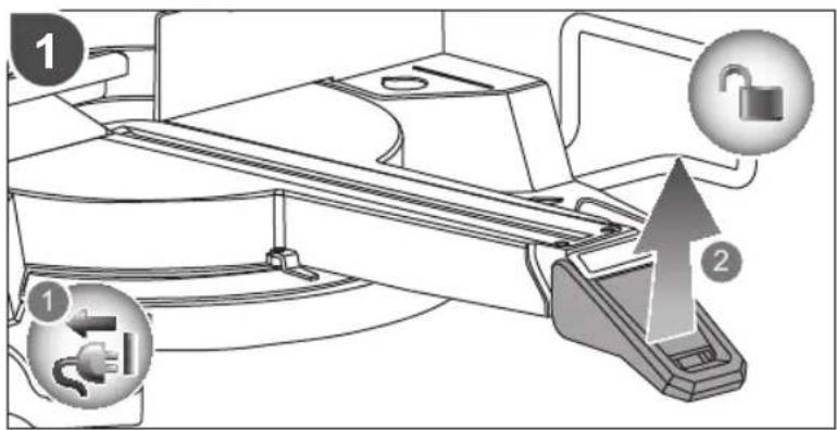
■ Always make sure the power plug has been removed from the mains power source before making adjustments, lubricating or when doing any maintenance on the product.
■ Before and after each use, check the product for damage or broken parts. Keep the product in top working condition by immediately replacing parts with spares approved by the manufacturer.
■ The blade has sharp edges and may also remain hot after cutting operations. Exercise extreme caution when cleaning an exposed blade. Wear gloves to yourself from personal injury.
- Clean the saw and its accessories from dust regularly, especially moving parts including the blade guard. Use a hand brush or vacuum cleaner to remove dust effectively. Do not use compressed air.
■ To assure safety and reliability, all repairs, including changing brushes, should be performed by an authorised service centre.
If the power cord is damaged, it must be replaced by an authorised service center in order to avoid a hazard.
WARNING
Do not attempt to disassemble the blade guard assembly for cleaning or repair. Damaged guards should not be used. Return to an authorised service centre for repair or replacement.
WARNING
For greater safety and reliability, all repairs should be performed by an authorised service centre.
Maximum cutting depth stop
The maximum cutting depth stop is to prevent the sa blade from cutting into the metal base of the unit. s screw
WARNING
The maximum cutting depth stop is not user adjustable. Do not adjust the maximum cutting depth stop.
TRANSPORTATION AND STORAGE
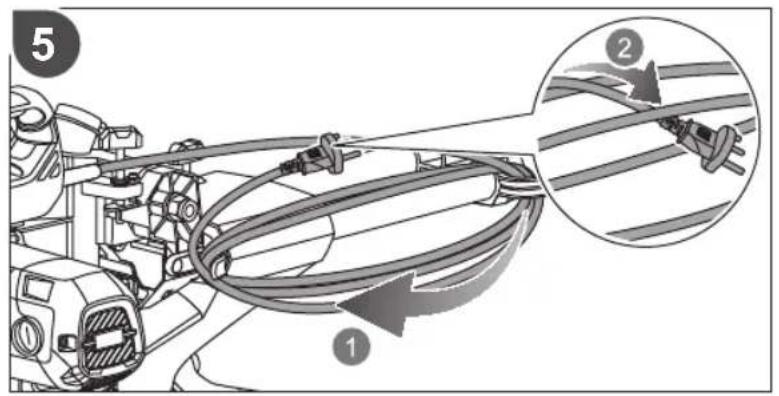
- When storing the product, disconnect the power cord. Store the product in a secure place that is not accessible to children. Store the power cord as shown in the illustration on page 248 - 249 of this manual.
■ Clean the product using a brush and vacuum cleaner before storage.
If you remove the saw blade or keep spares with the unit, ensure they are in the original packaging to prevent injury.
To secure the product prior to movement:
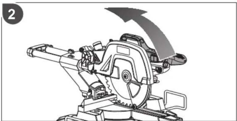
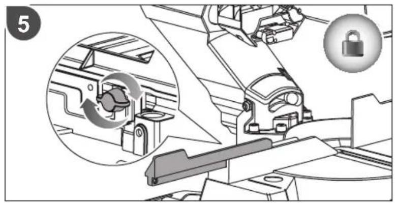
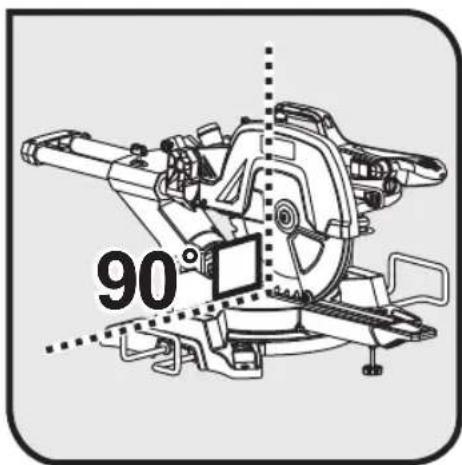
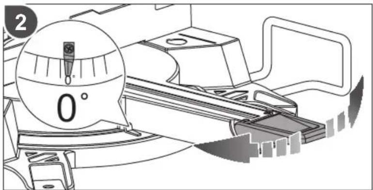
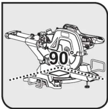
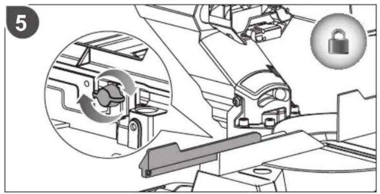
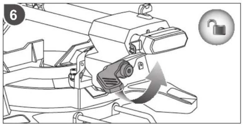
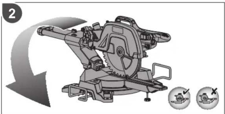
■ The product should be stored at the zero degree mitre and bevel angle and locked in position. The slide should be locked. The handle should be locked in the lower (safe) position with the guards closed.
■ One or both sides of the work piece supports can be removed for ease of carrying.
To move or transport in a vehicle:
- Secure the product prior to movement as described in protect the manual.
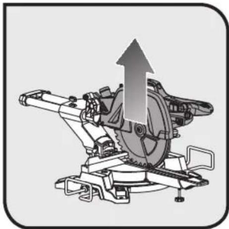
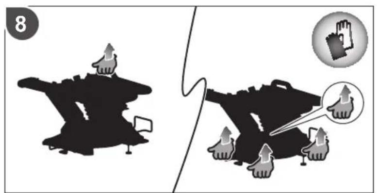
■ Remove the product from the bench top by releasing the 4 bolts, one at each corner. Secure the bolts for future use. Lift the product using the handle at the top.
■ When lifting to a height, two persons wearing heavy gloves are needed to lift the base of the product.
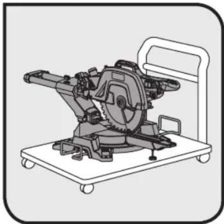
■ When transporting in a vehicle, set the product on its base and secure against movement.
ENVIRONMENTAL PROTECTION
Recycle raw materials instead of disposing of as waste. The machine, accessories and packaging should be sorted for environmental-friendly recycling.
SYMBOL

Safety alert
CE conformity
EurAsian conformity mark

Please read the instructions carefully before starting the machine.

Class II tool, double insulation

Wear ear protection

Always wear eye protection.

Keep hands away from the cutting area and sharp blade.
Wear safety gloves

Blade rotation direction (shown on saw blade)

Blade rotation direction (shown on blade guard)

Blade width of cut (Kerf)
Number of teeth on this saw blade
For cutting wood and analogous material

Not for cutting metals
Laser radiation. Do not stare into beam. Class 2 laser product
Waste electrical products should not be disposed of with household waste. Please recycle where facilities exist. Check with Local Authority or retailer for recycling advice.
SYMBOLS IN THIS MANUAL

Plug in the product.

Unplug the product.

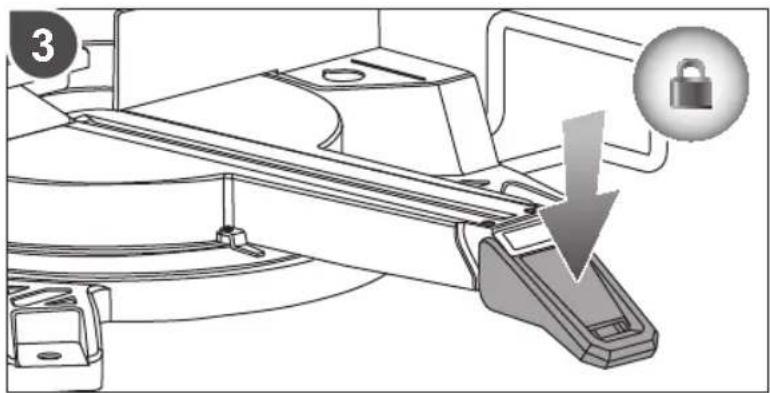
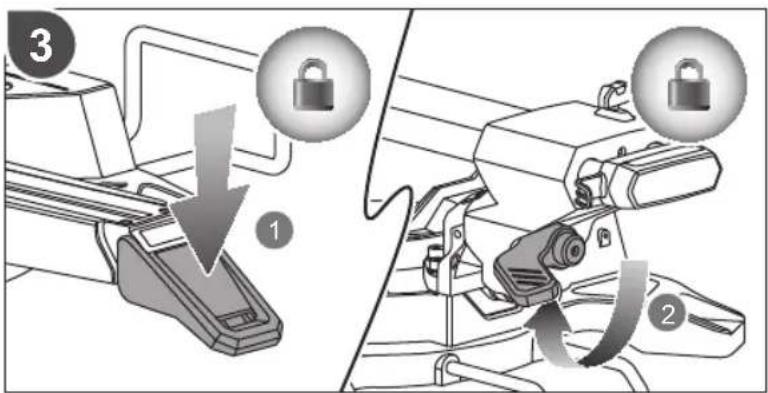
Lock

Unlock
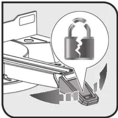
Locking mechanism is not working

A sound is heard
Waiting time for blade to reach full speed or stop completely.

Parts or accessories sold separately

Note

Warning
The following signal words and meanings are intended to explain the levels of risk associated with this product:
DANGER
Indicates an imminently hazardous situation, which, if not avoided, will result in death or serious injury.
WARNING
Indicates a potentially hazardous situation, which, if not avoided, could result in death or serious injury.
CAUTION
Indicates a potentially hazardous situation, which, if not avoided, may result in minor or moderate injury.
CAUTION
(Without Safety Alert Symbol) Indicates a situation that may result in property damage.
SÉCURITÉ RELATIVE AU LASER
MACHEN SIE SICH MIT IHREM PRODUKT VERTRAUT
EurAsian-symbol overeenstemming. van
KJENN PRODUKTET DITT
Se sida 222 - 223.
TRANSPORT OCH FÖRVARING
SYMBOLER I MANUALLEN

SIKKERHET PÅ ARBEIDSOMRÅDET
KJENN PRODUKTET DITT
Se side 222 - 223.
VEDLIKEHOLD OG OPPBEVARING
ÜLDISED OHUTUSREEGLID
HDIATUS
NURGASAAGIDE OHUTUSJUHISED
(Without Safety Alert Symbol) Indicates a situation that may result in property damage.
DODATNA VARNOSTNA OPOZORILA
OBOZNÁMTE SA S VAŠÍM PRODUKTOM
natural_image
Technical line drawing of a mechanical cutting tool with no visible text or symbols
natural_image
Two technical illustrations: one showing a tool with a bracket and cable, the other showing a screwdriver with a plus symbol (no text or labels)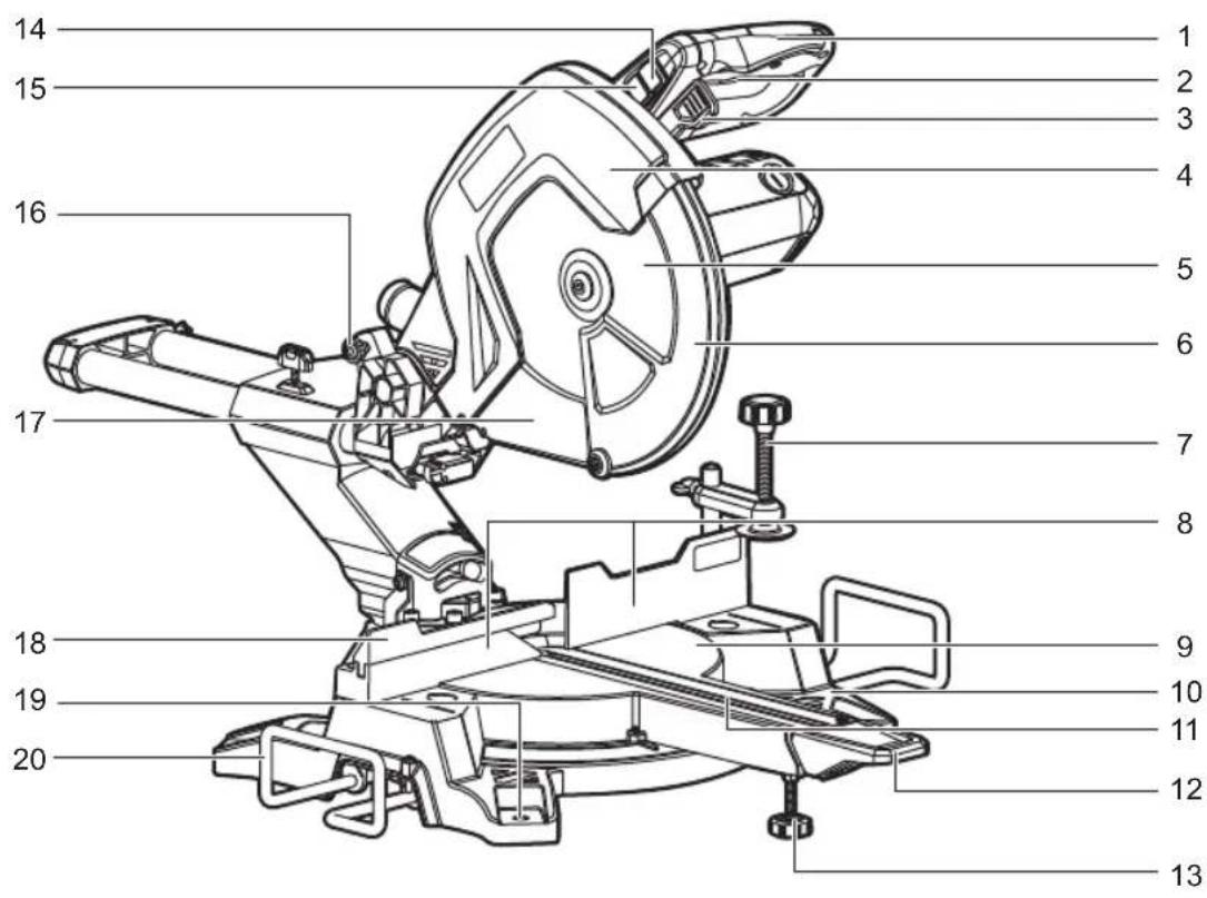


1
2
5

6
flowchart
graph TD
    A["Motor Switch"] --> B{Switch Breaker}
    B -->|Yes| C["Check Valve"]
    B -->|No| D["Adjust Control"]
    C --> E["Switch Breaker"]
    D --> F["Electrical Control"]
    style A fill:#f9f,stroke:#333
    style E fill:#ccf,stroke:#333
    style F fill:#ccf,stroke:#333

3
4
natural_image
Technical line drawing of a mechanical assembly with no visible text or symbols7
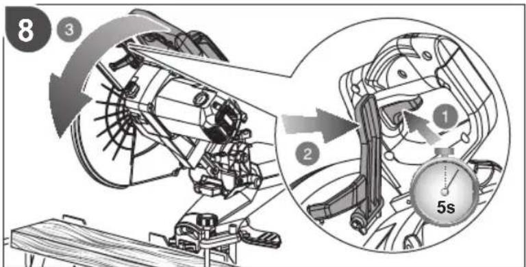
8
natural_image
Illustration of a plug and wire with an arrow, alongside a magnified view of a welding or welding process (no text or symbols)
natural_image
Mechanical assembly diagram showing a cutting machine with an upward arrow indicating motion (no text or symbols present)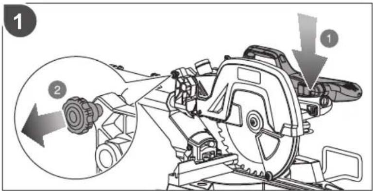
natural_image
Mechanical device diagram showing a cutting tool with a blade and rotating wheel (no text or symbols)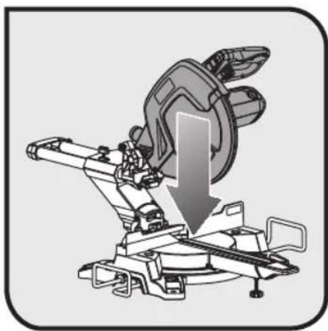
natural_image
Mechanical assembly diagram showing a cutting tool with a downward arrow indicating motion (no text or symbols present)

natural_image
Mechanical assembly diagram showing a clamping mechanism with arrows indicating motion (no text or symbols present)

natural_image
Technical illustration of a mechanical cutting machine with no visible text or symbols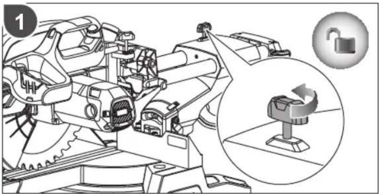
natural_image
Technical illustration of a mechanical assembly with an inset showing a padlock and a rotating component (no text or symbols present)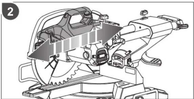
natural_image
Technical illustration of a mechanical cutting machine with internal components and mounting base (no text or symbols)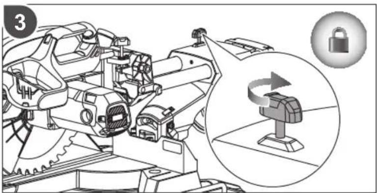

natural_image
Technical illustration of a mechanical gear assembly with mounting base (no text or symbols)
natural_image
Three-step diagram showing a mechanical tool with gear and base, illustrating progressive machining or assembly (no text or symbols)
natural_image
Technical illustration of a mechanical device with a sun symbol above it, showing no text or symbols present.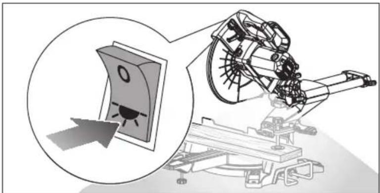
natural_image
Diagram of a mechanical device with a circular inset showing a button labeled 'O' and an arrow pointing to it, no text or symbols present.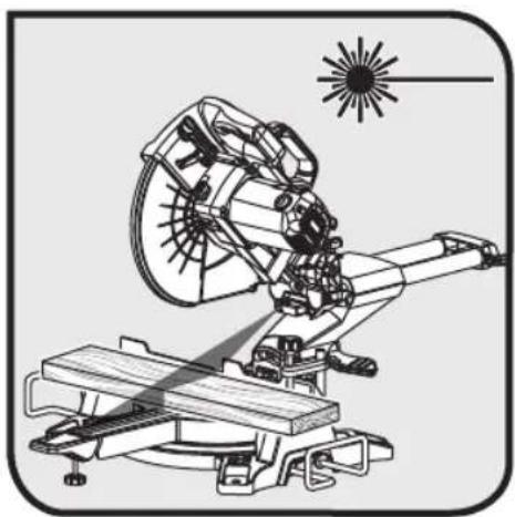
natural_image
Technical line drawing of a mechanical device with a sun symbol above (no text or labels)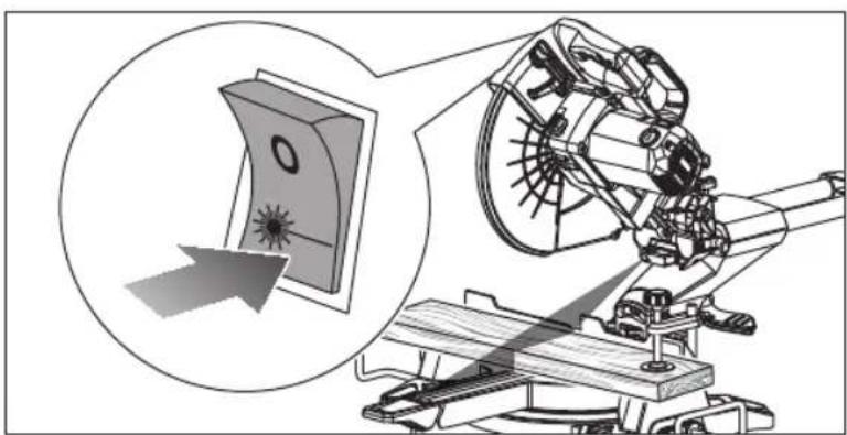
natural_image
Technical illustration of a mechanical device with an inset showing a circular component and a pointer, no visible text or symbols.
natural_image
Technical illustration of a mechanical assembly with a wheel and rotating components (no text or symbols)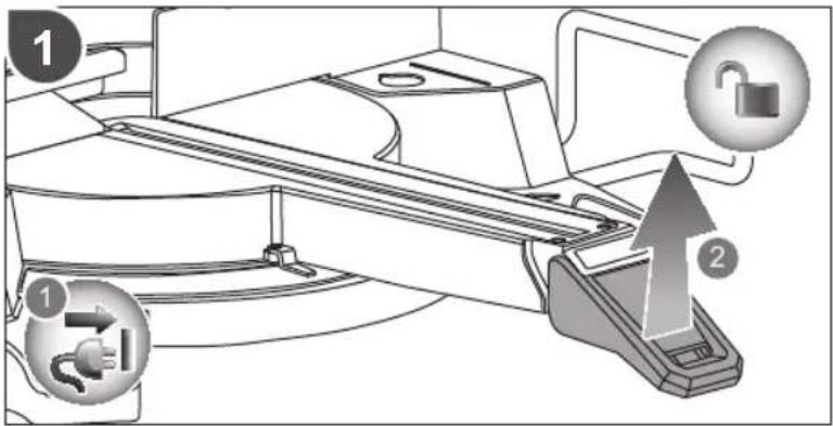
natural_image
Technical diagram showing a wooden beam supported by two clamps, with arrows indicating force or movement (no text or symbols present)
natural_image
Mechanical assembly diagram showing a rotating mechanism with wooden base and lock icon (no text or symbols)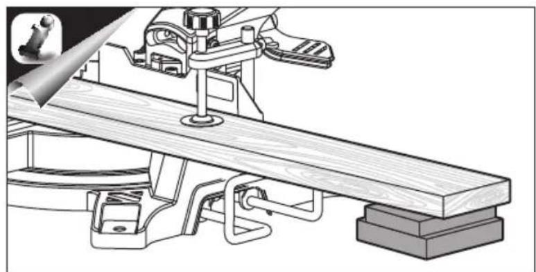
natural_image
Technical line drawing of a mechanical assembly with wooden base and support components (no text or symbols)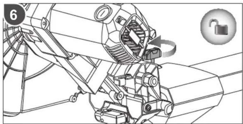
natural_image
Technical line drawing of a mechanical assembly with no visible text or symbols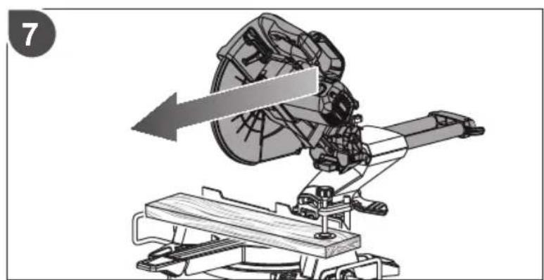
natural_image
Mechanical assembly diagram showing a rotating component mounted on a platform with an arrow indicating motion direction (no text or symbols present)
natural_image
Technical illustration of a mechanical device with a blade and lever mechanism (no text or symbols)

natural_image
Illustration of a cutting machine with a blade and moving components, showing mechanical assembly (no text or symbols)


natural_image
Mechanical assembly diagram showing a lock mechanism with an open lock icon (no text or symbols)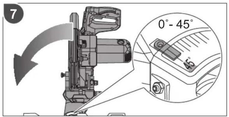

natural_image
Technical line drawing of a mechanical device with a lock icon and directional arrow (no text or symbols)
natural_image
Diagram of a wooden plank being lifted by a machine, showing force direction arrows (no text or symbols)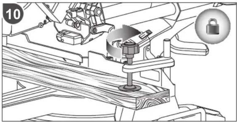
natural_image
Mechanical assembly diagram showing a clamping mechanism with a lock icon and numbered part (10), no readable text or symbols present.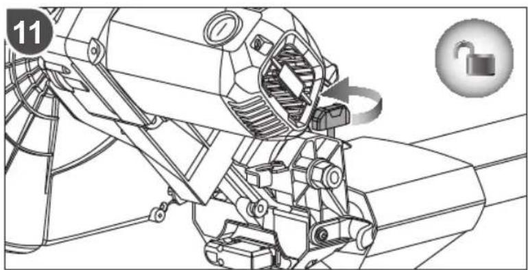
natural_image
Technical line drawing of a mechanical device with no visible text or symbols
natural_image
Illustration of a person operating a mechanical device with a tool, no text or symbols present
natural_image
Mechanical diagram of a cutting machine with a blade and wooden base, showing no text or symbols


natural_image
Technical illustration of a cutting machine with a gear and blade, showing mechanical components (no text or symbols)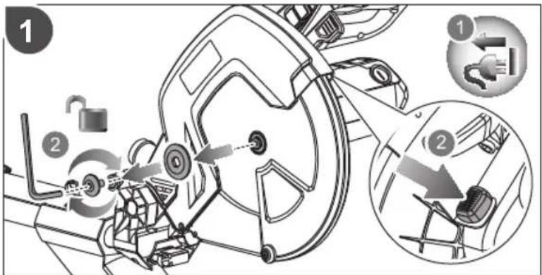
natural_image
Technical diagram of a mechanical assembly with an upward arrow indicating motion or force (no text or symbols present)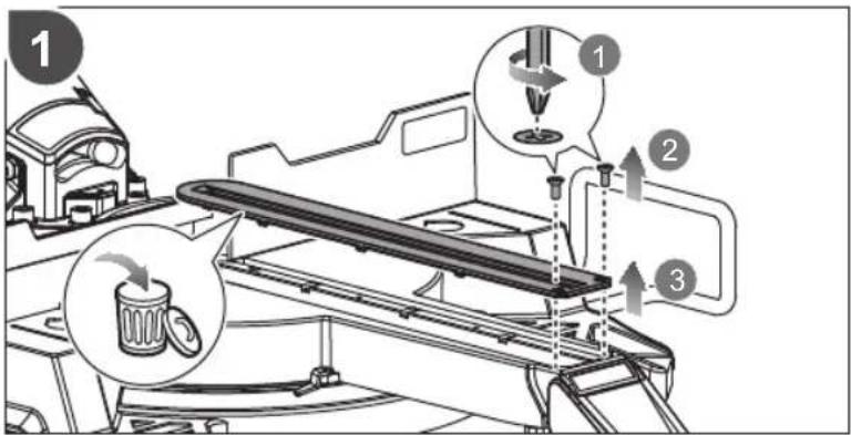

natural_image
Technical line drawing of a mechanical device with a 90-degree angle label (no readable text or symbols beyond the number)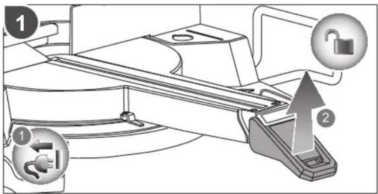


flowchart
graph TD
    A["Gear"] --> B{Rotating}
    B --> C["Check Valve"]
    C --> D["Lock Icon"]
    D --> E["Return Path"]
    E --> F["Actuator"]
    style A fill:#f9f,stroke:#333
    style B fill:#ccf,stroke:#333
    style C fill:#cfc,stroke:#333
    style D fill:#fcc,stroke:#333
    style E fill:#ffc,stroke:#333
    style F fill:#cff,stroke:#333

natural_image
Technical line drawing of a mechanical assembly with no visible text or symbols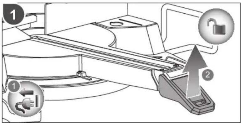


natural_image
Mechanical assembly diagram showing a lock mechanism with an open lock icon (no text or symbols)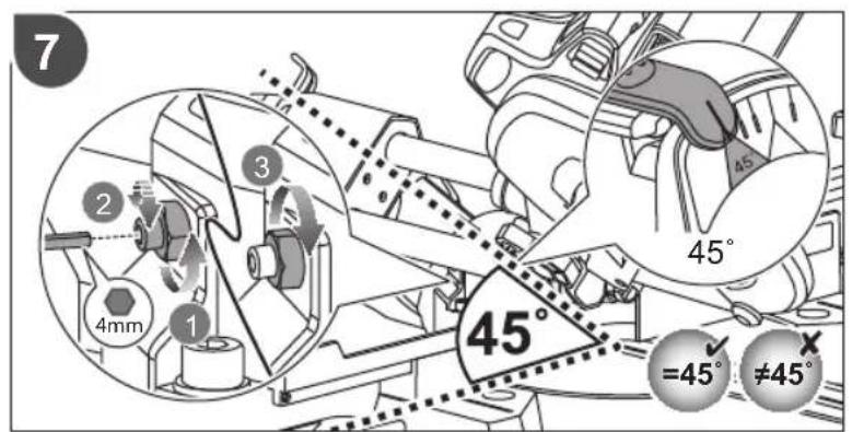
natural_image
Technical line drawing of a mechanical device with a lock icon and numbered label (8), showing internal components and motion arrows (no text or symbols)
natural_image
Illustration of a computer monitor with a lock icon and a magnified view of its lock mechanism (no text or symbols)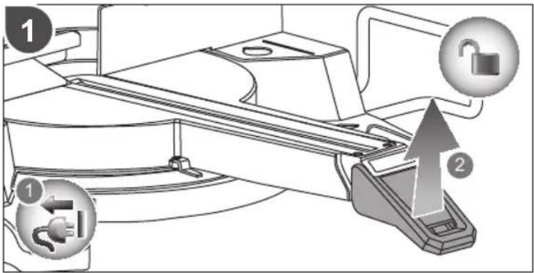

natural_image
Technical line drawing of a mechanical device on a wheeled platform (no text or symbols)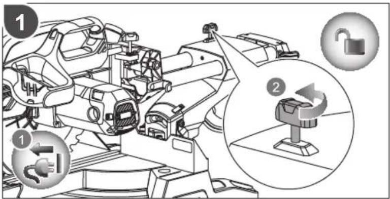
natural_image
Technical line drawing of a mechanical assembly with no visible text or symbols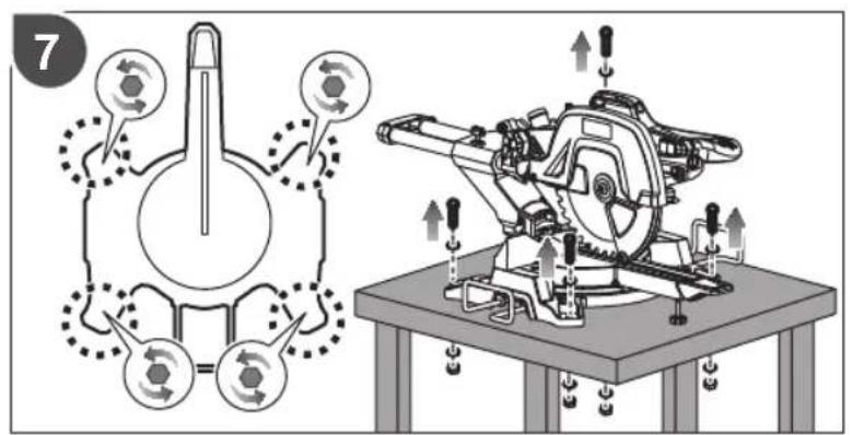
| EnglishFrançaisDeutschEspañolItalianoNederlandsPortuguês | ||||||
| Product specifications | Caractéristiques de l'appareil | Produkt-Spezifikationen | Especificaciones del producto | Specifiche prodotto Products | specificaties Especificações do produto | |
| Mitre saw Scie à onglet Gehungskappsäge Ingletadora Sega per tagli obliqui Verstekzaag Serra de esquadria | ||||||
| Model Modèle Modell | Modelo Modello | Modelo | Modelo | |||
| Net weight | Poids net | Nettogewicht | Peso netto | Peso netto | Nettogewicht | Peso líquido |
| Blade diameter | Diamètre du disque de coupe | Sägeblattdurchmesser | Diámetro de la hoja | Diametro lama | Zaagbladdiameter | Diámetro da lâmina |
| Arbor hole | Trou de broche | Aufnahmebohrung | Hueco del eje | Foro dell'albero | Asgat | Orificio do eixo |
| Blade teeth | Nombre de dents | Sägezähne | Dientes de la hoja | Denti lame | Zaagbladtanden | Dentes da lâmina |
| Width of cut | Largeur de coupe | Breite des Schnitts | Ancho del corte | Ampiezza di taglio | Maalbreedte | Largura do corte |
| No-load speed r/min. (RPM) | Vitesse à vide tr/min (tr.min-1) | Leerlaufdrehzahl U/min | Velocidad sin carga r/min. (RPM) | Velocità a vuolo r/min. (RPM) | Onbelast toerental t/min. (TPM) | Velocidade em vazio r/min. (RPM) |
| Input | Alimentation | Spannung | Cargador | Alimentazione | Input | Admissão |
| Power | Puissance | Leistung | Potencia | Alimentazione | Vermogen | Potência |
| Laser safety class | Classe de sécurité du laser | Laser Sicherheitsklasse | Tipo de seguridad láser | Classe di sicurezza laser | Laserveiligheidsklasse | Classe de segurança Laser |
| Cutting capacity | Capacité de coupe | Schnittleistung | Capacidad de corte | Capacità di taglio | Zaagcapaciteit | Capacidade de corte |
| Mitre 0° x bevel 0° | Onglet 0° x biseau 0° | Gehrung 0° x Neigung 0° | Inglete 0° x bisel 0° | Angolazione 0° x smussatura 0° | Verstek 0° x afschuining 0° | Esquadria 0° x bisel 0° |
| Mitre 0° x bevel 45° | Onglet 0° x biseau 45° | Gehrung 0° x Neigung 45° | Inglete 0° x bisel 45° | Angolazione 0° x smussatura 45° | Verstek 0° x afschuining 45° | Esquadria 0° x bisel 45° |
| Mitre 45°(Left) x bevel 0° | Onglet 45°(Gauche) x biseau 0° | Gehrung 45°(Links) x Neigung 0° | Inglete 45° (izquierda) x bisel 0° | Angolazione 45°(Sinistra) x sussatura 0° | Verstek 45° (links) x afschuining 0° | Esquadria 45° (esquerda) x bisel 0° |
| Mitre 45°(Right) x bevel 0° | Onglet 45°(Droit) x biseau 0° | Gehrung 45°(Rechts) x Neigung 0° | Inglete 45° (derecha) x bisel 0° | Angolazione 45°(Destra) x smussatura 0° | Verstek 45° (rechts) x afschuining 0° | Esquadria 45° (direita) x bisel 0° |
| Mitre 45°(Left) x bevel 45° | Onglet 45°(Gauche) x biseau 45° | Gehrung 45°(Links) x Neigung 45° | Inglete 45° (izquierda) x bisel 45° | Angolazione 45°(Sinistra) x sussatura 45° | Verstek 45° (links) x afschuining 45° | Esquadria 45° (esquerda) x bisel 45° |
| Mitre 45°(Right) x bevel 45° | Onglet 45°(Droit) x biseau 45° | Gehrung 45°(Rechts) x Neigung 45° | Inglete 45° (derecha) x bisel 45° | Angolazione 45°(Destra) x smussatura 45° | Verstek 45° (rechts) x afschuining 45° | Esquadria 45° (direita) x bisel 45° |
| Min. workpiece dimensions | Dimensions min. de la pièce | Min. Werkstückabmes-sungen | Dimensiones min. de la pieza de trabajo | Min. misurazione massima dei pezzi | Min. werkstukafmeting | Dimensões min. da peça de trabalho |
| Measured values determined according to EN 62841 A-weighted sound pressure level | Valeurs mesurées obtenues selon EN 62841 Niveau de pression sonore pondérée-A | Gemäß EN 62841 gemessene Werte A-bewerteter Schalldruckpegel | Valores medidos determinados de acuerdo con EN 62841 Nivel de presión acústica ponderada en A | Valori misurati determinati in accordo con lo standard EN 62841 Livello di pressione sonora pesato A | Valeurs mesurées obtenues selon EN 62841 A-gewogen geluidsdrukniveau | Valores medios calculados de acordo com EN 62841 Nivel de pressão sonora ponderada A |
| Uncertainty K | Incertitude K | Unsicherheit K | Incertidumbre K | Incertezza K | Onzekerheid K | Incerteza K |
| Measured values determined according to EN 62841 A-weighted sound power level | Valeurs mesurées obtenues selon EN 62841 Niveau de puissance sonore pondérée-A | Gemäß EN 62841 gemessene Werte A-bewerteter Schallleistungspegel | Valores medidos determinados de acuerdo con EN 62841 Nivel de potencia acústica ponderada en A | Valori misurati determinati in accordo con lo standard EN 62841 Livello di potenza sonora pesato A | Valeurs mesurées obtenues selon EN 62841 A-gewogen geluidsniveau | Valores medios calculados de acordo com EN 62841 Nivel de potência sonora ponderada A |
| Uncertainty K | Incertitude K | Unsicherheit K | Incertidumbre K | Incertezza K | Onzekerheid K | Incerteza K |
| Replacement parts: | Pièces de rechange: | Ersatzteile: | Piezas de repuesto: | Parti di ricambio: | Vervangonderdelen: | Peças de substituição: |
| Saw blade | Lame de scie | Sägeblatt | Cuchilla de la sierra | Lama sega | Zaagblad | Lâmina da serra |
| Kerf plate | Plaque de trait de scie | Schnittplatte | Placa de corte | Piastra intagliata | Kerfplaat | Placa de corte |


| DanskSvenskaSuomiNorskPycckii | Polski | |||||
| Produktspecifikationer Produktspecifikationer | Tuotteen teknisettiedot | Produktspesifikasjoner Xapakteristikni udelingia Paramery techniczne | ||||
| Geringssav Geringssag Viistesana Gjersag Topzov-ycovohna nila Pilarka ukosowa | ||||||
| Model | Modell | Malli | Modell | Modelb | Model | EMS305RG |
| Nettovægt | Nettovikt | Kokonaispaino | Nettovekt | Bec netto | Masa netto | 20,7 kg |
| Klingediameter | Klingdiameter | Terän läpimitta | Bladdiameter | Diametr pejungero dicska | Średnica tarczy tnącej | 305 mm |
| Spindelhul | Spindelhål | Karan reikä | Spindelhull | Rabocce otberstie | Otwör trzpienia | 30 mm |
| Klingetaender | Sågstand | Terän hampaat | Bladtenner | Число зубьев | Liczba zebów tarczy | 48 |
| Snitbredde | Skärbredd | Leikkauksen leveys | Bredde på kappet | Ширina paizreza | Szerokość cięcia | 2,6 mm |
| Tomgangshastighedomdr/min. (RPM) | Tomgangshastighetv/min (varv per minut) | Tyhjäkäyntinopeuskierr/min (RPM) | Hastighet ubelasleto/min. (RPM) | Скорость на xolostom xodyob/min | Prędkość bez obciążeniacobr./min. (RPM) | 5000 |
| Strømforsyning | Matningsspänning | Virrankulutus | Input | Питанe | Zasilanie | 220V - 240V~ 50 Hz |
| Effekt | Ström | Teho | Effekt | Mochnostb | Moc | 2200 W |
| Lasersikkerhedsklasse | Säkerhetsklassad laser | Laserin turvallisuus-luokitus | Laser sikkerhetsklasse | Klass cootretstembia lazernoi bezopacnosti | Klasa bezpiecieżnstwa lasera | II |
| Savekapacitet | Skärkapacitet | Leikkuukapasiteetti | Sagekapasitet | Pejungar spocobnostb | Zakres możliwości cięcia | |
| Gering 0° x smig 0° | Lutning 0° x vinkel 0° | Viiste 0° x sarmä 0° | Gjæsring 0° x skräkan 0° | Yogon повorota 0° x yoganakloha 0° | Ukos 0° x skos 0° | 110 mm x 300 mm |
| Gering 0° x smig 45° Lutning 0° | x vinkel 45° Viste 0° x sarmä 45° | Viiste 45° (vasen) xsarmä 0° | Gjæsring 0° x skräkan 45° | Yogon повorota 0° x yoganakloha 45° | Ukos 0° x skos 45° | 70 mm x 300 mm |
| Gering 45°(venstre) x smig 0° | Lutning 45 (vänster) x vinkel 0° | Viiste 45° (veisen) xsarmä 0° | Gjæsring 45°(venstre) x skräkan 0° | Yogon повorota 45°(blevo) x yogon nakloha 0° | Ukos 45°(w lewo) x skos 0° | 110 mm x 210 mm |
| Gering 45°(højre) x smig 0° | Lutning 45 (höger) x vinkel 0° | Viiste 45° (oikea) xsarmä 0° | Gjæsring 45°(høyre) x skräkan 0° | Yogon повorota 45°(blawo) x yogon nakloha 0° | Ukos 45°(w prawo) x skos 0° | 110 mm x 210 mm |
| Gering 45°(venstre) x smig 45° | Lutning 45 (vänster) x vinkel 45° | Viiste 45° (vasen) xsarmä 45° | Gjæsring 45°(venstre) x skräkan 45° | Yogon повorota 45°(blevo) x yogon nakloha 45° | Ukos 45°(w lewo) x skos 45° | 70 mm x 210 mm |
| Gering 45°(højre) x smig 45° | Lutning 45 (höger) x vinkel 45° | Viiste 45° (oikea) xsarmä 45° | Gjæsring 45°(høyre) x skräkan 45° | Yogon повorota 45°(blawo) x yogon nakloha 45° | Ukos 45°(w prawo) x skos 45° | 70 mm x 210 mm |
| Min. mal på arbejdsemner | Min. avmätning avarbetsstycket | Työkappaleenminimaalinen | Min. verktöyma | Minimalnyal paamereby | Min. wymiary przedmiotuobrabianego | 130 mm x 35 mm x 2,5 mm |
| Mälte vaerdier bestemmes i henhold til EN 62841A-vægtet lydtryksniveau | Värden uppmätta enligtEN 62841A-vägd ljudtrycksniva | Mitatut arvotmääretyty EN 62841-standardin mukaanA-painotettuaänenpainetaso | Mälte verdier i samsvarmed EN 62841A-vektel lydtrykkniiva | Izmerenhe zacheninga opredeleny b cootretstembic EN 62841Urowen A-vzbewnho#o zbywoboro давlenia | Zmierzone wartosci okreslonewg EN 62841A-wazony poziom ciśnieniahafasu | L_pa = 98,5 dB(A) |
| Usikkerhed K | Osäkerhet K | Epätarkkuus K | Usikkerhet K | Paźbros K | Niepewnosć pomiaru K | 3 dB(A) |
| Mälte vaerdier bestemmes i henhold til EN 62841A-vägtet lydeffektniveau | Värden uppmätta enligtEN 62841A-vägd ljudeffektsniva | Mitatut arvotmääretyty EN 62841-standardin mukaanA-painotettuaänenetho | Mälte verdier i samsvarmed EN 62841A-vektel lydeffektniva | Izmerenhe zacheninga opredeleny b cootretstembic EN 62841Urowen A-vzbewnho#o zbywoboro maschostb | Zmierzone wartosci okreslonewg EN 62841A-wazony poziom natężeniiahafasu | L_pa = 111 dB(A) |
| Usikkerhed K | Osäkerhet K | Epätarkkuus K | Usikkerhet K | Paźbros K | Niepewnosć pomiaru K | 3 dB(A) |
| Reservedele: | Utbytesdelar; | Varaosat; | Reservedeler; | Заласные частi; | Częsci zamienne; | |
| Savklinge | Sågblad | Sahanterä | Sagblad | Пильhoe polotno | Tarca tnaça | 5131038188 |
| Snitplade | Platta för sagsnitt | Kerf-levy | Kantplate | Torцевaa plastina | Wstawka stolowa | 5131038294 |


| Čeština | Magyar | Română | Latviski | Lietuviškai | Eesti |
| Technické údaje produktu | Termék műszaki adatai | Specificațiile produsului | Produkta specifikácijas | Gaminio techninės savybės | Toote tehnilised andmed |
| Pokosová pila Gérvágó fűrész F | Férästräu unghiular Lenjczágis | Skersinis pjūklas Miusaag | |||
| Model | Tipus | Model | Modelis | Modelis | Mudeli tähis |
| Čistá hmotnost | Nettó tömeg | Greutate netă | Svars neto | Neto svoris | Netomass |
| Prümër kotouče | Tárcsa átmérője | Diametru lamă | Asmens diamets | Pjovimo disko skersmuo | Saeketta läbimõõt |
| Otvor hřidele | Tengelyfurat | Orificiu arbore | Värpstas atvere | Ašies anga | Võlliava |
| Zub kotouče | Fürészlap fogai | Dinte lamă | Asmens zobi | Geležtės dantukų skaičius | Lõiketera hammas |
| Širka řezu | Vágás szélessège | Látjme a täierii | Griezuma platums | Pjovimo plotis | Lõikelaius |
| Otáčky naprázdno ot./min. (RPM) | Üresjáratí fordulatszám ford./perc (RPM) | Viteză în gol rot/min. (RPM) | Apgriezieni bez slodzes apgr./min. (RPM) | Greitis be apkrovimo aps./min. (apsukų per minutę) | Kírus ilma koormuseta p/min. (p/min) |
| Vstup | Bemenet | Intrare | Ieeja | Ivestis | Vooluvõrk |
| Výkon | Teljesítmény | Alimentare | Străva | Galia | Võimsus |
| Třída laserové bezpečnosti | Lézer biztonsági osztály | Clasă de siguranjă laser | Lázera drošības klase | Lazerio saugos klasė | Laseri ohutusklass |
| Maximální prořez | Vágásteljesítmény | Capacitate de täiere | Zăgëšanas ražība | Pjovimo talpa | Lõikesügavu |
| Pokos 0° x úkos 0° | Gérvágás 0° x ferdevágás 0° | Unghi 0° x täietură la 0° | Lençis 0° x slīpums 0° | Užkarpa 0° x nuožambis 0° | Kaldlõige 0° x nurklõige 0° |
| Pokos 0° x úkos 45° | Gérvágás 0° x ferdevágás 45° | Unghi 0° x täietură la 45° | Lençis 0° x slīpums 45° | Užkarpa 0° x nuožambis 45° | Kaldlõige 0° x nurklõige 45° |
| Pokos 45°(vlevo) x úkos 0° | Gérvágás 45°(bal) x ferdevágás 0° | Unghi de 45°(Stânga) x täietură la 0° | Lençis 45°(pa kreisi) x slīpums 0° | Užkarpa 45°(kairėje) x nuožambis 0° | Kaldlõige 45° (vasak) x nurkõige 0° |
| Pokos 45°(vpravo) x úkos 0° | Gérvágás 45°(jobb) x ferdevágás 0° | Unghi de 45°(Dreapta) x täietură la 0° | Lençis 45°(pa labi) x slīpums 0° | Užkarpa 45°(dešinėje) x nuožambis 0° | Kaldlõige 45° (parem) x nurkõige 0° |
| Pokos 45°(vlevo) x úkos 45° | Gérvágás 45°(bal) x ferdevágás 45° | Unghi de 45°(Stânga) x täietură la 45° | Lençis 45°(pa kreisi) x slīpums 45° | Užkarpa 45°(kairėje) x nuožambis 45° | Kaldlõige 45° (vasak) x nurkõige 45° |
| Pokos 45°(vpravo) x úkos 45° | Gérvágás 45°(jobb) x ferdevágás 45° | Unghi de 45°(Dreapta) x täietură la 45° | Lençis 45°(pa labi) x slīpums 45° | Užkarpa 45°(dešinėje) x nuožambis 45° | Kaldlõige 45° (parem) x nurkõige 45° |
| Min. rozměry obrobku Min. mun | cadarab méretek | Dimensiunile minimă ale piesei de prelucrat | Min.. apstrădăjamăs detaljas izměrs | Min. apdorojamos detalės matmenys | Min. tooriku mööumed |
| Naměřené hodnoty zjištěné dle EN 62841Hladina akustického tlaku vážená funkci A | A mért értékek meghatározása az EN 62841 szerint törléntA-súlyozott hangnyomásszint | Valori măsurate determinate în conformitate cu EN 62841Nivel de presiune acustică ponderată A | Izměrítãs vērtības saskaņa ar EN 62841A-līmena skaņas spiediena līmenis | Išmatuotosios vertės nustatytos pagal EN 62841A svertinis garso slėgio lygis | Mõõteväärtused on kindlaks määratud vastavalt standardile EN 62841A-kaalutud helirõhu tase |
| Nejistota K | Bizonytalanság K | Incertitudine K | Klūdas vērtība K | Nepastovumas K | Mõõtemääramatus K |
| Naměřené hodnoty zjištěné dle EN 62841Hladina akustického vykonu vážená funkci A | A mért értékek meghatározása az EN 62841 szerint törléntA-súlyozott hangteljesítményszint | Valori măsurate determinate în conformitate cu EN 62841Nivel de putere acustică ponderată A | Izměrítãs vērtības saskaņa ar EN 62841A-līmena skaņas jaudas līmenis | Išmatuotosios vertės nustatytos pagal EN 62841A svertinis garso galios lygis | Mõõteväärtused on kindlaks määratud vastavalt standardile EN 62841A-kaalutud helirõhu tase |
| Nejistota K | Bizonytalanság K | Incertitudine K | Klūdas vērtība K | Nepastovumas K | Mõõtemääramatus K |
| Náhradní dilly: | Cserealkatrészzek: | Piese de schimb: | Rezerves dajas: | Atsarginės detalės: | Asendusosad: |
| Pilový kotouč | Fürészlap | Lama ferästrăului | Zāga asmens | Pjūkdo geležtė | Saeleht |
| Deska řezu | Körfürészlap | Plăcută cu făgaș | Asmens ierobežotāja plăksne | Plokšte su ipjova | Lõikeplaat |


The declared noise emission value(s) have been measured in accordance with a standard test method of EN 62841-1 and EN 62841-3-9, and may be used for comparing one tool with another.
The declared noise value(s) may also be used in a preliminary assessment of exposure.
The noise emissions during actual use of the power tool can differ from the declared values depending on the ways in which the tool is used especially what kind of workpiece is processed.
Identify safety measures to protect the operator based on an estimation of exposure in the actual conditions of use (taking account of all parts of the operating cycle such as the times when the tool is switched off and when it is running idle in addition to the trigger time).
Wear hearing protection. Exposure to noise can cause hearing loss.

AVERTISSEMENT
The noise emissions during actual use of the power tool can differ from the declared values depending on the ways in which the tool is used especially what kind of workpiece is processed.
In addition to any statutory rights resulting from the purchase, this product is covered by a warranty as stated below.
- The warranty period is 24 months for consumers and commences on the date the product was purchased. This date has to be documented by an invoice or other proof of purchase. The product is designed and dedicated to consumer and private use only. So there is no warranty provided in case of professional or commercial use. This warranty applies only on new products.
- There is a possibility to extend for a part of the range (AC/DC) the warranty period over the period described above using the registration on the www.ryobitools.eu website. The eligibility of products for extended warranty is clearly displayed in stores and / or on packaging and is contained within the product documentation. The end user is required to register his/her newly-acquired products online within 30 days from the date of purchase. The end user may register for the extended warranty in his/her country of residence if listed on the online registration form where this option is valid. Furthermore, end users must give their consent to the storage of their personal data that is required to be entered online. They must also accept the terms and conditions. The registration confirmation receipt, which is sent out by e-mail, and the original invoice showing the date of purchase will serve as proof of the extended warranty.
- The warranty covers all defects of the product during the warranty period due to faults in workmanship or material at the purchase warranty is limited to repair and/or replacement and does not include any other obligations including but not limited to incidental or consequential damages. The warranty is not valid if the product has been misused, used contrary to the instruction manual, or has been incorrectly connected to a power supply. This warranty does not apply to:
– any damage to the product that is the result of improper or lack of maintenance
—any product that has been altered or modified
– any product where original identification (trade mark, serial number) markings have been defaced, altered or removed
– any damage caused by non-observance of the instruction manual
– any product not displaying the CE approval mark on the rating plate
– any product that has been attempted to be repaired by a non-authorised warranty service centre or without prior authorisation by Techtronic Industries
– any product connected to improper power supply (amps, frequency)
– any damage caused by external influences (water, chemical, physical, shocks) or foreign substances
– normal wear and tear spare parts
– inappropriate use, overloading of the tool
– use of non-approved accessories or parts
- Power tool accessories provided with the tool or purchased separately, including but not limited to screw driver bits, drill bits, abrasive discs, sand paper and blades, lateral guide, etc.
- Components (parts and accessories) subject to natural tear, including but not limited to service & maintenance kits, carbon brushes, bearings, chuck, SDS drill bit attachment or reception, power cord, auxiliary handle, transport carry case, sanding plate, dust bag, dust exhaust tube, felt washers, impact wrench pins & springs, etc.
- For servicing, the product must be sent or presented to a RYOBI authorised service station listed for each country in the following list of service station addresses. In some countries your local RYOBI dealer undertakes to send the product to the RYOBI service organisation. When sending a product to a RYOBI service station, the product should be safely packed without any dangerous contents such as petrol, marked with sender's address and accompanied by a short description of the fault.
- A repair / replacement under this warranty is free of charge. It does not constitute an extension or a new start of the warranty period. Exchanged parts or products become our property. In some countries delivery charges or postage will have to be paid by the sender. Your statutory rights arising from the purchase of the product remain unaffected
- This warranty is valid in the European Community, Switzerland, Iceland, Norway, Liechtenstein, Turkey and Russia. Outside these areas, please 6, contact your authorised RYOBI dealer to determine if another applies.
AUTHORISED SERVICE CENTRE
To find an authorised service centre near you, visit http://uk.rycheader/service-and-support/service-agents
FR RYOBI® CONDITIONS D'APPLICATION DE LA GARANTIE
DECLARATION OF CONFORMITY
Techtronic Industries GmbH
Max-Eyth-Straße 10, 71364 Winnenden, Germany
Herewith we declare that the product
Mitre Saw
Brand: RYOBI
Model number: EMS305RG
Serial number range: 47500001000001 - 47500001999999
is in conformity with the following European Directives and harmonised standards
2006/42/EC, 2014/30/EU, 2011/65/EU
EN 55014-1:2017; EN 55014-2:2015;
EN 61000-3-2:2014; EN 61000-3-11:2000;
EN 62841-1:2015; EN 62841-3-9:2015+A11:2017
RoHS documentation is compiled according to EN 50581:2012

CE
Todd Chipner
Sr. Director, Regulatory & Safety
Winnenden, May. 17, 2019
Authorised to compile the technical file:
Alexander Krug, Managing Director
Techtronic Industries GmbH
Max-Eyth-Straße 10, 71364 Winnenden, Germany

DÉCLARATION DE CONFORMITÉ
Techtronic Industries GmbH
Max-Eyth-Straße 10, 71364 Winnenden, Germany
Winnenden, May, 17, 2019
Max-Eyth-Straße 10, 71364 Winnenden, Germany

Max-Eyth-Straße 10, 71364 Winnenden, Germany
Winnenden, May. 17, 2019
Max-Eyth-Straße 10, 71364 Winnenden, Germany

Max-Eyth-Straße 10, 71364 Winnenden, Germany
Winnenden, May. 17, 2019
Max-Eyth-Straße 10, 71364 Winnenden, Germany
CE

Max-Eyth-Straße 10, 71364 Winnenden, Germany
Winnenden, May. 17, 2019
Max-Eyth-Straße 10, 71364 Winnenden, Germany
CE

CONFORMITEITSVERKLARING
Techtronic Industries GmbH
Max-Eyth-Straße 10, 71364 Winnenden, Germany
Winnenden, May. 17, 2019
Max-Eyth-Straße 10, 71364 Winnenden, Germany
CE


Max-Eyth-Straße 10, 71364 Winnenden, Germany
Winnenden, May. 17, 2019
Max-Eyth-Straße 10, 71364 Winnenden, Germany

OVERENSSTEMMELSESERKLAERING
Techtronic Industries GmbH
Max-Eyth-Straße 10, 71364 Winnenden, Germany
Vi erklærer hermed, at produktet
Geringssav
Brand: RYOBI
Winnenden, May. 17, 2019
Max-Eyth-Straße 10, 71364 Winnenden, Germany

KONFORMITETSDEKLARATION
Techtronic Industries GmbH
Max-Eyth-Straße 10, 71364 Winnenden, Germany
Härmed deklarerar vi all produklerma
Geringssåg
Märke: RYOBI
Winnenden, May. 17, 2019
Max-Eyth-Straße 10, 71364 Winnenden, Germany

SÄÄNNÖSTEN NOUDATTAMINEN
Techtronic Industries GmbH
Max-Eyth-Straße 10, 71364 Winnenden, Germany
Winnenden, May. 17, 2019
Max-Eyth-Straße 10, 71364 Winnenden, Germany

SAMSVARSERKLÆRING
Techtronic Industries GmbH
Max-Eyth-Straße 10, 71364 Winnenden, Germany
Winnenden, May. 17, 2019
Max-Eyth-Straße 10, 71364 Winnenden, Germany

Max-Eyth-Straße 10, 71364 Winnenden, Germany
Winnenden, May. 17, 2019
Max-Eyth-Straße 10, 71364 Winnenden, Germany


DEKLARACJA ZGODNOŚCI
Techtronic Industries GmbH
Max-Eyth-Straße 10, 71364 Winnenden, Germany
Winnenden, May. 17, 2019
Max-Eyth-Straße 10, 71364 Winnenden, Germany

DECLARATIE DE CONFORMITATE
Techtronic Industries GmbH
Max-Eyth-Straße 10, 71364 Winnenden, Germany
Winnenden, May. 17, 2019
Alexander Krug, Director General
Techtronic Industries GmbH
Max-Eyth-Straße 10, 71364 Winnenden, Germany

PROHLÁŠENÍ O SHODĚ
Techtronic Industries GmbH
Max-Eyth-Straße 10, 71364 Winnenden, Germany
Winnenden, May. 17, 2019
Max-Eyth-Straße 10, 71364 Winnenden, Germany

ATBILSTĪBAS DEKLARĀCIJA
Techtronic Industries GmbH
Max-Eyth-Straße 10, 71364 Winnenden, Germany
Winnenden, May. 17, 2019
Max-Eyth-Straße 10, 71364 Winnenden, Germany


MEGFELELŐSÉGI NYILATKOZAT
Techtronic Industries GmbH
Max-Eyth-Straße 10, 71364 Winnenden, Germany
Winnenden, May. 17, 2019
Max-Eyth-Straße 10, 71364 Winnenden, Germany

ATITIKTIES PAREIŠKIMAS
Techtronic Industries GmbH
Max-Eyth-Straße 10, 71364 Winnenden, Germany
Winnenden, May. 17, 2019
Max-Eyth-Straße 10, 71364 Winnenden, Germany

VASTAVUSDEKLARATSIOON
Techtronic Industries GmbH
Max-Eyth-Straße 10, 71364 Winnenden, Germany
Kinnitame, et see toode
Miiusaag
Mark: RYOBI
Mudeli number: EMS305RG
Seerianumbri vahemik: 47500001000001 - 47500001999999
Winnenden, May. 17, 2019
Max-Eyth-Straße 10, 71364 Winnenden, Germany

PREHLÁSENIE O ZHODE
Techtronic Industries GmbH
Max-Eyth-Straße 10, 71364 Winnenden, Germany
Winnenden, May. 17, 2019
Max-Eyth-Straße 10, 71364 Winnenden, Germany

IZJAVA O USKLAĐENOSTI
Techtronic Industries GmbH
Max-Eyth-Straße 10, 71364 Winnenden, Germany
Winnenden, May. 17, 2019
Max-Eyth-Straße 10, 71364 Winnenden, Germany

Max-Eyth-Straße 10, 71364 Winnenden, Germany
Winnenden, May. 17, 2019
Max-Eyth-Straße 10, 71364 Winnenden, Germany

IZJAVA O SKLADNOSTI
Techtronic Industries GmbH
Max-Eyth-Straße 10, 71364 Winnenden, Germany
Winnenden, May. 17, 2019
Max-Eyth-Straße 10, 71364 Winnenden, Germany

Max-Eyth-Straße 10, 71364 Winnenden, Germany
Winnenden, May. 17, 2019
Max-Eyth-Straße 10, 71364 Winnenden, Germany


UYGUNLUK BEYANI
Techtronic Industries GmbH
Max-Eyth-Straße 10, 71364 Winnenden, Germany
Winnenden, May. 17, 2019
Max-Eyth-Straße 10, 71364 Winnenden, Germany

ΔΗΛΩΣΗ ΣΥΜΜΟΡΦΩΣΗΣ
Techtronic Industries GmbH
Max-Eyth-Straße 10, 71364 Winnenden, Germany
Winnenden, May. 17, 2019
Max-Eyth-Straße 10, 71364 Winnenden, Germany


EN RYOBI is a trademark of Ryobi Limited, and is used under license.
71364 Winnenden, Germany
20190426v5