DTD157Z - Drill MAKITA - Free user manual and instructions
Find the device manual for free DTD157Z MAKITA in PDF.
Download the instructions for your Drill in PDF format for free! Find your manual DTD157Z - MAKITA and take your electronic device back in hand. On this page are published all the documents necessary for the use of your device. DTD157Z by MAKITA.
USER MANUAL DTD157Z MAKITA
Cordless Impact Driver INSTRUCTION MANUAL 4
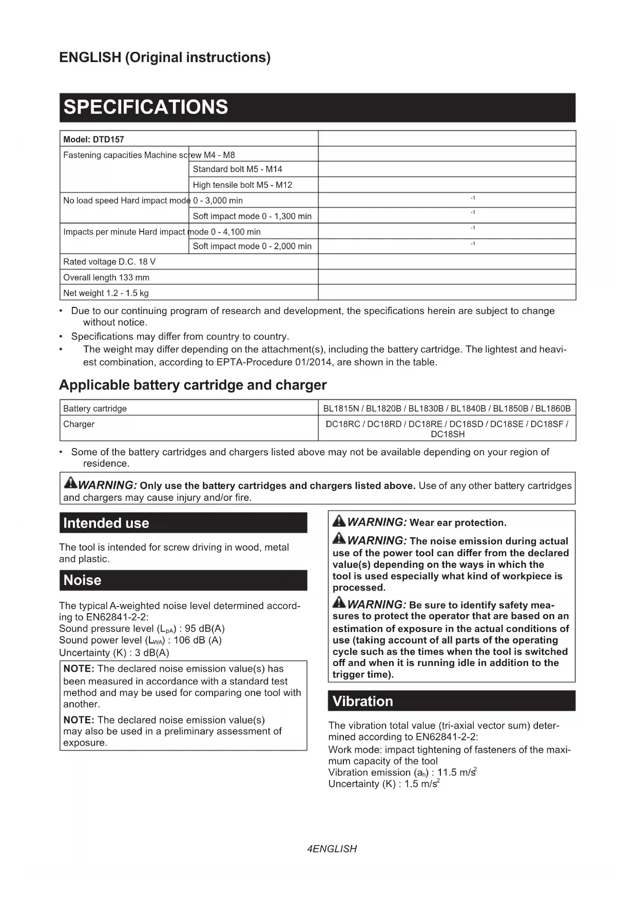
Rated voltage D.C. 18 V Overall length 133 mm Net weight 1.2 - 1.5 kg
- Duetoourcontinuingprogramofresearchanddevelopment,thespecicationshereinaresubjecttochange without notice.
- Specicationsmaydierfromcountrytocountry.
- Theweightmaydierdependingontheattachment(s),includingthebatterycartridge.Thelightestandheavi- est combination, according to EPTA-Procedure 01/2014, are shown in the table. Applicable battery cartridge and charger Batterycartridge BL1815N / BL1820B / BL1830B / BL1840B / BL1850B / BL1860B Charger DC18RC / DC18RD / DC18RE / DC18SD / DC18SE / DC18SF / DC18SH
- Someofthebatterycartridgesandchargerslistedabovemaynotbeavailabledependingonyourregionof residence.
WARNING: Only use the battery cartridges and chargers listed above.Useofanyotherbatterycartridges
andchargersmaycauseinjuryand/orre. Intended use The tool is intended for screw driving in wood, metal and plastic. Noise ThetypicalA-weightednoiseleveldeterminedaccord- ing to EN62841-2-2: Soundpressurelevel(L
WARNING: Wear ear protection.
WARNING: The noise emission during actual
use of the power tool can dier from the declared value(s) depending on the ways in which the tool is used especially what kind of workpiece is processed.
WARNING: Be sure to identify safety mea-
sures to protect the operator that are based on an estimation of exposure in the actual conditions of use (taking account of all parts of the operating cycle such as the times when the tool is switched o and when it is running idle in addition to the trigger time). Vibration Thevibrationtotalvalue(tri-axialvectorsum)deter- mined according to EN62841-2-2: Work mode: impact tightening of fasteners of the maxi- mumcapacityofthetool Vibrationemission(a
WARNING: The vibration emission during
actual use of the power tool can dier from the declared value(s) depending on the ways in which the tool is used especially what kind of workpiece is processed.
WARNING: Be sure to identify safety mea-
sures to protect the operator that are based on an estimation of exposure in the actual conditions of use (taking account of all parts of the operating cycle such as the times when the tool is switched o and when it is running idle in addition to the trigger time). EC Declaration of Conformity For European countries only TheECdeclarationofconformityisincludedasAnnexA to this instruction manual. SAFETY WARNINGS General power tool safety warnings
WARNING: Read all safety warnings, instruc-
tions, illustrations and specications provided with this power tool. Failure to follow all instructions listedbelowmayresultinelectricshock,reand/or seriousinjury. Save all warnings and instruc- tions for future reference. Theterm"powertool"inthewarningsreferstoyour mains-operated(corded)powertoolorbattery-operated (cordless)powertool. Cordless impact driver safety warnings
1. Hold the power tool by insulated gripping
surfaces, when performing an operation where the fastener may contact hidden wiring. Fastenerscontactinga"live"wiremaymake exposed metal parts of the power tool "live" and could give the operator an electric shock.
2. Always be sure you have a rm footing.
Be sure no one is below when using the tool in high locations.
3. Hold the tool rmly.
4. Wear ear protectors.
5. Do not touch the bit or the workpiece immedi-
ately after operation. They may be extremely hot and could burn your skin.
6. Keep hands away from rotating parts.
7. Use auxiliary handle(s), if supplied with the
tool.Lossofcontrolcancausepersonalinjury.
8. Hold the power tool by insulated gripping
surfaces, when performing an operation where the cutting accessory may contact hidden wiring.Cuttingaccessorycontactinga"live" wiremaymakeexposedmetalpartsofthepower tool "live" and could give the operator an electric shock.
9. Make sure there are no electrical cables, water
pipes, gas pipes etc. that could cause a hazard if damaged by use of the tool. SAVE THESE INSTRUCTIONS.
WARNING: DO NOT let comfort or familiarity
with product (gained from repeated use) replace strict adherence to safety rules for the subject product. MISUSE or failure to follow the safety rules stated in this instruction manual may cause serious personal injury. Important safety instructions for battery cartridge
1. Before using battery cartridge, read all instruc-
tions and cautionary markings on (1) battery charger, (2) battery, and (3) product using battery.
2. Do not disassemble or tamper with the battery
cartridge.Itmayresultinare,excessiveheat, or explosion.
3. If operating time has become excessively
shorter, stop operating immediately. It may result in a risk of overheating, possible burns and even an explosion.
4. If electrolyte gets into your eyes, rinse them
out with clear water and seek medical atten- tion right away. It may result in loss of your eyesight.
5. Do not short the battery cartridge:
(1) Do not touch the terminals with any con- ductive material. (2) Avoid storing battery cartridge in a con- tainer with other metal objects such as nails, coins, etc. (3) Do not expose battery cartridge to water or rain. A battery short can cause a large current ow, overheating, possible burns and even a breakdown.
6. Do not store and use the tool and battery car-
tridge in locations where the temperature may reach or exceed 50 °C (122 °F).
7. Do not incinerate the battery cartridge even if
it is severely damaged or is completely worn out. The battery cartridge can explode in a re.
8. Do not nail, cut, crush, throw, drop the battery
cartridge, or hit against a hard object to the battery cartridge.Suchconductmayresultina re,excessiveheat,orexplosion.
9. Do not use a damaged battery.6 ENGLISH
10. The contained lithium-ion batteries are subject
to the Dangerous Goods Legislation require- ments. Forcommercialtransportse.g.bythirdparties, forwarding agents, special requirement on pack- aging and labeling must be observed. For preparation of the item being shipped, consult- ing an expert for hazardous material is required. Pleasealsoobservepossiblymoredetailed national regulations. Tapeormaskoopencontactsandpackupthe batteryinsuchamannerthatitcannotmove around in the packaging.
11. When disposing the battery cartridge, remove
it from the tool and dispose of it in a safe place. Follow your local regulations relating to disposal of battery.
12. Use the batteries only with the products
specied by Makita. Installing the batteries to non-compliantproductsmayresultinare,exces- siveheat,explosion,orleakofelectrolyte.
13. If the tool is not used for a long period of time,
the battery must be removed from the tool.
14. During and after use, the battery cartridge may
take on heat which can cause burns or low temperature burns. Pay attention to the han- dling of hot battery cartridges.
15. Do not touch the terminal of the tool imme-
diately after use as it may get hot enough to cause burns.
16. Do not allow chips, dust, or soil stuck into the
terminals, holes, and grooves of the battery cartridge.Itmayresultinpoorperformanceor breakdownofthetoolorbatterycartridge.
17. Unless the tool supports the use near
high-voltage electrical power lines, do not use the battery cartridge near high-voltage electri- cal power lines.Itmayresultinamalfunctionor breakdownofthetoolorbatterycartridge.
18. Keep the battery away from children.
SAVE THESE INSTRUCTIONS. CAUTION: Only use genuine Makita batteries. Use of non-genuine Makita batteries, or batteries that havebeenaltered,mayresultinthebatterybursting causingres,personalinjuryanddamage.Itwill alsovoidtheMakitawarrantyfortheMakitatooland charger. Tips for maintaining maximum battery life
1. Charge the battery cartridge before completely
discharged. Always stop tool operation and charge the battery cartridge when you notice less tool power.
Never recharge a fully charged battery cartridge. Overcharging shortens the battery service life.
Charge the battery cartridge with room tempera- ture at 10 °C - 40 °C (50 °F - 104 °F). Let a hot battery cartridge cool down before charging it.
4. When not using the battery cartridge, remove
it from the tool or the charger.
5. Charge the battery cartridge if you do not use
it for a long period (more than six months). FUNCTIONAL DESCRIPTION CAUTION: Always be sure that the tool is switched o and the battery cartridge is removed before adjusting or checking function on the tool. Installing or removing battery cartridge CAUTION: Always switch o the tool before installing or removing of the battery cartridge. CAUTION: Hold the tool and the battery car- tridge rmly when installing or removing battery cartridge.Failuretoholdthetoolandthebattery cartridgermlymaycausethemtoslipoyourhands andresultindamagetothetoolandbatterycartridge andapersonalinjury. ►Fig.1: 1. Red indicator 2. Button 3.Batterycartridge Toremovethebatterycartridge,slideitfromthetool while sliding the button on the front of the cartridge. Toinstallthebatterycartridge,alignthetongueonthe batterycartridgewiththegrooveinthehousingandslip itintoplace.Insertitallthewayuntilitlocksinplace withalittleclick.Ifyoucanseetheredindicatoronthe uppersideofthebutton,itisnotlockedcompletely. CAUTION: Always install the battery cartridge fully until the red indicator cannot be seen. If not, itmayaccidentallyfalloutofthetool,causinginjuryto youorsomeonearoundyou. CAUTION: Do not install the battery cartridge forcibly.Ifthecartridgedoesnotslideineasily,itis notbeinginsertedcorrectly. Indicating the remaining battery capacity Only for battery cartridges with the indicator ►Fig.2: 1. Indicator lamps 2. Check button Pressthecheckbuttononthebatterycartridgetoindi- catetheremainingbatterycapacity.Theindicatorlamps light up for a few seconds. Indicator lamps Remaining capacityLighted O Blinking75% to 100%50% to 75%25% to 50%0% to 25%Charge the battery.Thebatterymayhavemalfunctioned.7 ENGLISH NOTE: Depending on the conditions of use and the ambienttemperature,theindicationmaydierslightly fromtheactualcapacity. NOTE:Therst(farleft)indicatorlampwillblinkwhen thebatteryprotectionsystemworks. Tool / battery protection system Thetoolisequippedwithatool/batteryprotectionsys- tem.Thissystemautomaticallycutsopowertothe motortoextendtoolandbatterylife.Thetoolwillauto- maticallystopduringoperationifthetoolorbatteryis placed under one of the following conditions: Overheat protection Whenthetool/batteryisoverheated,thetoolstops automaticallyandthelampblinks.Inthissituation,let thetool/batterycoolbeforeturningthetoolonagain. Overdischarge protection Whenthebatterycapacityisnotenough,thetoolstops automatically.Inthiscase,removethebatteryfromthe toolandchargethebattery. Switch action ►Fig.3: 1. Switch trigger CAUTION: Before installing the battery car- tridge into the tool, always check to see that the switch trigger actuates properly and returns to the "OFF" position when released. Tostartthetool,simplypulltheswitchtrigger.Tool speedisincreasedbyincreasingpressureontheswitch trigger. Release the switch trigger to stop. NOTE:Thetoolautomaticallystopsifyoukeeppull- ing the switch trigger for about 6 minutes. Electric brake This tool is equipped with an electric brake. If the tool consistentlyfailstoquicklystopaftertheswitchtrigger is released, have the tool serviced at a Makita service center. Lighting up the front lamp CAUTION: Do not look in the light or see the source of light directly. ►Fig.4: 1. Lamp ►Fig.5: 1. Button Pulltheswitchtriggertoturnonthelamp.Toturno, releaseit.Thelampgoesoutapproximately10seconds after releasing the switch trigger. Tokeepthelampo,turnothelampstatus.Firstpull and release the switch trigger. And then press the but- ton for one second within 10 seconds. To turn on the lamp status again, press the button again similarly. NOTE:Toconrmthelampstatus,pullthetrigger. Whenthelamplightsupbypullingtheswitchtrigger, the lamp status is ON. When the lamp does not come on, the lamp status is OFF. NOTE:Whenthetoolisoverheated,thelightashes foroneminute,andthentheLEDdisplaygoeso.In this case, cool down the tool before operating again. NOTE:Useadryclothtowipethedirtothelensof the lamp. Be careful not to scratch the lens of lamp, or itmaylowertheillumination. Reversing switch action ►Fig.6: 1. Reversing switch lever CAUTION: Always check the direction of rotation before operation. CAUTION: Use the reversing switch only after the tool comes to a complete stop. Changing the directionofrotationbeforethetoolstopsmaydam- age the tool. CAUTION: When not operating the tool, always set the reversing switch lever to the neu- tral position. This tool has a reversing switch to change the direction of rotation. Depress the reversing switch lever from the A side for clockwise rotation or from the B side for coun- terclockwise rotation. When the reversing switch lever is in the neutral posi- tion, the switch trigger cannot be pulled.8 ENGLISH Changing the impact force ►Fig.7: 1. Hard 2. Soft 3. A mode 4. Changed in three steps 5. Button You can change the impact force in three steps: hard, soft, and A mode. This allows a tightening suitable to the work. Everytimethebuttonispressed,thenumberofblows changes in three steps. “Amode(assistmode)”isaneasy-to-usemodefor driving screws with good control. In this mode, the tool drives a screw with low-speed rotationatrst.Afterthetoolstartstoimpact,therota- tion speed increases and reaches the maximum speed. Youcanchangetheimpactforcewithinapproximately one minute after releasing the switch trigger. Impact force grade displayed on panel Maximum blows Purpose Example of application Hard 4,100 min
(/min) Tightening when force and speed are desired. Tightening wood screws, tightening bolts. Soft 2,000 min
(/min) Tightening with less force to avoid screw thread breakage. Tightening sash screws, tight- ening small screws such as M6. A mode 4,100 min
(/min) Tightening screws with better control. Tightening long screws. NOTE:Amodeisavailableonlywhenthetoolrotatesclockwise.WhenrotatingcounterclockwiseinAmode,the impact force and speed are the same as hard mode. NOTE:Whenalllampsontheswitchpanelgoout,thetoolisturnedotosavethebatterypower.Theimpactforce gradecanbecheckedbypullingtheswitchtriggertotheextentthatthetooldoesnotoperate. NOTE: While pulling the switch trigger, the impact force grade cannot be changed. ASSEMBLY CAUTION: Always be sure that the tool is switched o and the battery cartridge is removed before carrying out any work on the tool. Installing or removing driver bit/ socket bit ►Fig.8 Useonlydriverbit/socketbitthathasinsertingportion showninthegure.Donotuseanyotherdriverbit/ socket bit. For tool with shallow driver bit hole A=12mm B=9mm Useonlythesetypeofdriver bit. Follow the procedure 1.(Note)Bit-pieceisnot necessary. For tool with deep driver bit hole A=17mm B=14mm Toinstallthesetypesofdriver bits, follow the procedure 1. A=12mm B=9mm Toinstallthesetypesofdriver bits, follow the procedure 2. (Note)Bit-pieceisnecessary for installing the bit. Procedure 1 ►Fig.9: 1. Driver bit 2. Sleeve To install the driver bit, pull the sleeve in the direction of the arrow and insert the driver bit into the sleeve as far as it will go. Then release the sleeve to secure the driver bit. Procedure 2 In addition to Procedure 1, insert the bit-piece into the sleeve with its pointed end facing in. ►Fig.10: 1. Driver bit 2. Bit-piece 3. Sleeve To remove the driver bit, pull the sleeve in the direction of the arrow and pull the driver bit out. NOTE: If the driver bit is not inserted deep enough into the sleeve, the sleeve will not return to its original position and the driver bit will not be secured. In this case,tryre-insertingthebitaccordingtotheinstruc- tions above. NOTE:Whenitisdiculttoinsertthedriverbit,pull the sleeve and insert it into the sleeve as far as it will go. NOTE: After inserting the driver bit, make sure that it isrmlysecured.Ifitcomesout,donotuseit.9 ENGLISH Installing hook CAUTION: When installing the hook, always secure it with the screw rmly. If not, the hook maycomeofromthetoolandresultinthepersonal injury. CAUTION: Use the hanging/mounting parts for their intended purposes only. Using for unin- tendedpurposemaycauseaccidentorpersonal injury. ►Fig.11: 1. Groove 2. Hook 3. Screw Thehookisconvenientfortemporarilyhangingthetool. This can be installed on either side of the tool. To install the hook, insert it into a groove in the tool housing on either side and then secure it with a screw. To remove, loosen the screw and then take it out. OPERATION ►Fig.12 Theproperfasteningtorquemaydierdependingupon the kind or size of the screw/bolt, the material of the workpiece to be fastened, etc. The relation between fas- teningtorqueandfasteningtimeisshowninthegures. Standard bolt
3. Proper fastening torque corresponding to each bolt
3. Proper fastening torque corresponding to each bolt
diameter Holdthetoolrmlyandplacethepointofthedriverbitinthescrew head.Applyforwardpressuretothetooltotheextentthatthebit willnotslipothescrewandturnthetoolontostartoperation. NOTICE: If you use a spare battery to continue the operation, rest the tool at least 15 min. NOTE: Use the proper bit for the head of the screw/ boltthatyouwishtouse. NOTE: When fastening M8 or smaller screw, choose aproperimpactforceandcarefullyadjustpressureon the switch trigger so that the screw is not damaged. NOTE: Hold the tool pointed straight at the screw. NOTE: Iftheimpactforceistoostrongoryoutightenthe screwforatimelongerthanshowninthegures,thescrewor thepointofthedriverbitmaybeoverstressed,stripped,dam- aged,etc.Beforestartingyourjob,alwaysperformatestoper- ationtodeterminetheproperfasteningtimeforyourscrew. Thefasteningtorqueisaectedbyawidevarietyof factorsincludingthefollowing.Afterfastening,always check the torque with a torque wrench.
Whenthebatterycartridgeisdischargedalmostcompletely, voltage will drop and the fastening torque will be reduced.
2. Driver bit or socket bit
Failure to use the correct size driver bit or socket bit will cause a reduction in the fastening torque.
4. The manner of holding the tool or the material
ofdrivingpositiontobefastenedwillaectthe torque.
5. Operating the tool at low speed will cause a reduc-
tion in the fastening torque. MAINTENANCE CAUTION: Always be sure that the tool is switched o and the battery cartridge is removed before attempting to perform inspection or maintenance. NOTICE: Never use gasoline, benzine, thinner, alcohol or the like. Discoloration, deformation or cracks may result. To maintain product SAFETY and RELIABILITY, repairs,anyothermaintenanceoradjustmentshould beperformedbyMakitaAuthorizedorFactoryService Centers,alwaysusingMakitareplacementparts. OPTIONAL ACCESSORIES CAUTION: These accessories or attachments are recommended for use with your Makita tool specied in this manual.Theuseofanyother accessories or attachments might present a risk of injurytopersons.Onlyuseaccessoryorattachment for its stated purpose. Ifyouneedanyassistanceformoredetailsregard- ingtheseaccessories,askyourlocalMakitaService Center.