Reserve R700 - Speaker POLK - Free user manual and instructions
Find the device manual for free Reserve R700 POLK in PDF.
User questions about Reserve R700 POLK
0 question about this device. Answer the ones you know or ask your own.
Ask a new question about this device
Download the instructions for your Speaker in PDF format for free! Find your manual Reserve R700 - POLK and take your electronic device back in hand. On this page are published all the documents necessary for the use of your device. Reserve R700 by POLK.
USER MANUAL Reserve R700 POLK
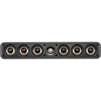
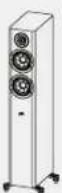
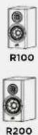
Center Channel Speakers
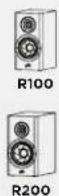
R100 AND R200
Bookshelf Speakers
POLK. EXPECT GREAT SOUND.
Contents
Expect Great Sound — The Polk Reserve Story ......2
Safety Instructions 3
What's in the Box 4
How to Connect Your System....4
Reserve Series Speaker Positioning....5
Caring for Your Reserve Loudspeakers....6
Specifications 7
Expect Great Sound—The Polk Reserve Story
Thank you for purchasing the Polk Reserve Series loudspeakers! Modern styling combined with Polk's premium Pinnacle tweeter and Turbine mid-range driver deliver high-resolution detail and imaging. With our detailed, deep effortless bass, you will enjoy a whole new listening experience. Pure and minimalist, the Polk Reserve Series is engineered and designed with your entertainment in mind.
Having built a reputation as the makers of great sound for more than 45 years, Polk Audio takes pride in superior sound and build quality, which feature many patented and award-winning audio innovations. For Polk, building audio products isn't just a job - it's a passion - to deliver great sound that is accessible for everyone.
Technical Assistance or Service
If your product was damaged during shipping, please contact the authorized Polk Audio retailer where you purchased your product. For technical support, FAQs, and repair information, visit http://polk.custhelp.com. For a complete list of contact information, visit https://www.polkaudio.com/contact-us. Support email addresses and phone numbers vary based on the region where your purchased your product.
WARNING: Listen Carefully
Polk Audio loudspeakers are capable of playing at extremely high volume levels, which could cause serious or permanent hearing damage. Polk Audio, Inc. accepts no liability for hearing loss, bodily injury, or property damage resulting from the misuse of its products. Keep these guidelines in mind and always use good judgment when controlling volume:
- Limit prolonged exposure to volume levels that exceed 85 decibels (dB). For more information about safe volume levels, take a look at the Occupational Health and Safety Administration (OSHA) guidelines at http://www.osha.gov/.
Product Disposal
Certain international, national and/or local laws and/or regulations may apply regarding the disposal of this product. For more information, please contact the retailer where you purchased this product or the Polk importer/distributor in your country. More information is also available at www.polkaudio.com or by contacting Polk Audio at 5541 Fermi Court, Carlsbad, California, 92008, USA. Phone: 1-800-377-7655.

This symbol on our electrical products or their packaging indicates that it is prohibited in Europe to discard this product(s) as domestic waste. In order to ensure that you dispose of the product(s) correctly, please dispose of the product(s) according to local laws and regulations on the disposal of electrical and electronic equipment. In doing so, you are contributing to the retention of natural resources and to the promotion of environmental protection by the treatment and disposal of electronic waste.

CAUTION
RISK OF ELECTRIC SHOCK DO NOT OPEN

CAUTION
TO REDUCE THE RISK OF ELECTRIC SHOCK, DO NOT REMOVE COVER (OR BACK). NO USER-SERVICEABLE PARTS INSIDE. REFER SERVICING TO QUALIFIED SERVICE PERSONNEL.

The lightning flash with arrowhead symbol, within an equilateral triangle, is intended to alert the user to the presence of uninsulated "dangerous voltage" within
the product's enclosure that may be of sufficient magnitude to constitute a risk of electric shock to persons.

The exclamation point within an equilateral triangle is intended to alert the user to the presence of important operating and maintenance (servicing) instructions in
the literature accompanying the appliance.
IMPORTANT SAFETY INSTRUCTIONS
- Read these instructions.
- Keep these instructions.
- Heed all warnings.
- Follow all instructions.
- Do not use this apparatus near water.
- Clean only with dry cloth.
- Do not block any ventilation openings. Install in accordance with the manufacturer's instructions.
- Do not install near any heat sources such as radiators, heat registers, stoves, or other apparatus (including amplifiers) that produce heat.
-
Only use attachments/accessories specified by the manufacturer.
-
Use only with the cart, stand, tripod, bracket, or table specified by the manufacturer, or sold with the apparatus. When a cart is used, use caution when moving the cart/apparatus combination to avoid injury from tip-over.
-
Refer all servicing to qualified service personnel. Servicing is required when the apparatus has been damaged in any way, such as power supply cord or plug is damaged, liquid has been spilled, or objects have fallen into the apparatus, the apparatus has been exposed to rain or moisture, does not operate normally, or has been dropped.

Notes On Use
WARNINGS
- Avoid high temperatures. Allow for sufficient heat dispersion when installed in a rack.
- Keep the unit free from moisture, water, and dust.
- Do not obstruct the ventilation holes.
- Do not let foreign objects into the unit.
- Do not let insecticides, benzene, and thinner come in contact with the unit.
- Never disassemble or modify the unit in any way.
- Ventilation should not be impeded by covering the ventilation openings with items, such as newspapers, tablecloths or curtains.
- Naked flame sources such as lighted candles should not be placed on the unit.
- Do not expose the unit to dripping or splashing fluids.
- Do not place objects filled with liquids, such as vases, on the unit.
CAUTION:
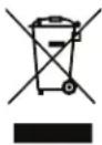
Use caution when unpacking speaker. Tweeter has a pointed tip and may cause injury. Replace speaker grille when not in use.
text_image
Warning sign and magnified view of a device with hand contact and spiral patternA Note About Recycling:
This product's packaging materials are recyclable and can be reused. Please dispose of any materials in accordance with the local recycling regulations. When discarding the unit, comply with local rules or regulations.
EU Declaration of Conformity
Hereby, [Sound United, LLC] declares that our product is in compliance with following EU/EC Directives. The full text of the EU declaration of conformity is available at the following internet address:
RoHS: 2011/65/EU, and amendment directive (EU) 2015/863 EU declaration of conformity URL:
https://www.polkaudio.com/declarations-of-conformity"
Sound United, LLC
5541 Fermi Court
Carlsbad, CA 92008
EU contact: Sound United Europe, A division of D&M Europe B.V. Beemdstraat 11, 5653 MA Eindhoven, The Netherlands
What's in the Box
Each box contains:
- Loudspeaker(s)
- Owner's Manual
- Registration Card
- Magnetic grilles
(Speaker cable not included)
How to Connect Your System
To get the best sound quality, it's important to wire your speakers correctly.
Wire Preparation
Follow the hookup directions included with your receiver/amplifier. Strip 0.5" (12.7mm) of insulation from each of the two conductors of the wire to expose the bare metal and twist each of the individual conductors into single un-frayed strands. Note that one of the terminals on the rear of each speaker is marked red (+) and the other is black (-). Make sure that you connect the wire from the positive (+) terminal of your amplifier or receiver to the red (+) terminal on your speaker and the wire from the negative (-) terminal of your amplifier or receiver to the black (-) terminal on your speaker. Most wire has some indicator (such as color-coding, ribbing or writing) on one of the two conductors to help you maintain consistency.
These recommendations are for all connections from the amplifier/receiver to each speaker:
Runs Minimum Wire Gauge
| Lengths up to 25' (5 m) 16 | |
| Lengths greater than 25' (5 m) but less than 50' (15 m) | 14 |
| Lengths greater than 50' (15 m) but less than 75' (25 m) | 12 |
| Lengths greater than 75' (25 m) 10 | |
Binding Posts
To connect wire to the binding post, unscrew the binding post cap and insert the bare wire into the hole near the base of the binding post. Do not insert the insulated part of the wire into the hole as this will not give you a good connection. Tighten the binding post cap until it seats firmly with the wire, but do not over tighten.

natural_image
Four identical mechanical component diagrams showing a cylindrical pin with threaded ends, arranged horizontally (no text or symbols)Connectors
You have several options when choosing connectors for your speaker wires, and it's really a matter of personal preference. Three of the more commonly used are banana plugs, spade lugs and bare wire. If you know where you want to locate your speakers and plan to set up your system and leave them there, then bare wire will work fine. Just make sure there are not stray strands of wire that could come into contact. If you like to experiment with different speaker locations, spade lugs or banana plugs offer more convenient options when it comes to disconnecting and reconnecting wires.
Basic Floor-Standing, Center, Bookshelf, and Height Module Speaker Hookup
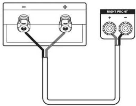
Make sure that the red (+) and black (-) connectors on your amplifier or receiver connect to the red (+) and black (-) connectors on your speakers. If your speakers sound "thin," with little bass and little or no center image, odds are that one of the speaker wires is connected backwards. Double check all connections.
text_image
RIGHT FRONT + -Bi-Wiring (R700 only)
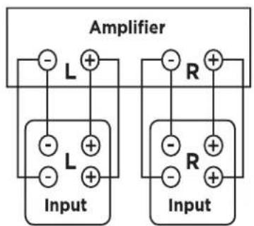
Bi-wiring can provide noticeable improvements in the overall transparency of your loudspeakers. After removing the jumpers, run separate speaker wires to the low and high frequency drivers from a single amplifier (the upper set of binding posts are for the high frequency drivers, the lower set of binding posts are for the low frequency drivers). Connect one set of speaker wires to the upper terminals on each speaker and one set of wires to the lower terminals. Connect the other ends of both wire sets to the same amplifier outputs. See amplifier/AV receiver user manual for configuration instructions (Figure 1).
text_image
Amplifier Input L + - L + - R + - R + - Input(Figure 1)
Bi-Amping (R700 only)
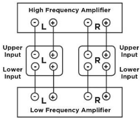
Bi-amping allows you to use separate amplifiers for the high and low frequency sections of your loudspeaker for greater dynamic range and lower distortion. We recommend that your separate amplifiers have identical gain to preserve the speaker's voicing balance. After removing the jumpers, connect the speaker wires from the high frequency amplifier outputs to the upper set of terminal posts on each speaker. Follow the same procedure for connecting the low frequency amplifier outputs to the lower set of terminals (Figure 2). Remember to maintain correct wiring polarity (+ to +, - to -) in all connections. See amplifier/AV receiver user manual for configuration instructions.
text_image
High Frequency Amplifier - L + Upper Input - L + Lower Input - L + Low Frequency Amplifier - R + Upper Input - R + Lower Input - R +(Figure 2)
Bass Management
When using your Reserve Series loudspeakers with a receiver or processor employing bass management in a home theater, we recommend the following settings:
R500, R600 and R700: set to "small" when using a subwoofer and set the crossover frequency between 40-80Hz. If no subwoofer is present in the system, set these to "large".
R100 and R200: set to "small" when using a subwoofer and set the crossover frequency between 50-80Hz.
R300, R350, R400: set to "small" when using a subwoofer and set the crossover frequency between 60-80Hz.
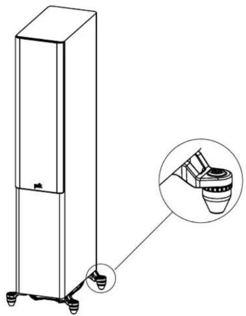
Rubber Feet and Adjustable Floor Spikes
Rubber feet and floor spikes are included with your Reserve floor-standing loudspeakers to anchor and stabilize the speaker on any type of floor. In order to expose the spike, simply pull the rubber feet off. The floor spikes can be adjusted from below and require two hands.
Note: If the speaker is stable on the floor, no adjustment is necessary. If the speaker is unstable, follow these steps:
- The speaker will be inclined to settle on three of the four spikes leaving one spike slightly off the floor.
- Determine which spike needs to be adjusted.
- Use the included Allen wrench to turn the spike clockwise to lower it and counterclockwise to raise it.
- As the spike contacts the floor, it will become more difficult to turn. At that point the speaker should be stabilized.
- Tighten the lock ring to prevent the spike from loosening over time.
natural_image
Line drawing of a vertical rectangular device with a small inset showing a close-up of its base component (no text or symbols present)Caring for Your Reserve Loudspeakers Enclosure Finish
Your Reserve loudspeakers are finished with a premium vinyl. To clean the panels, use a soft dry cloth. You may use furniture polish if needed. Never use harsh detergents or cleaning fluids. Note: Do not use any petroleum-based cleaners or solvents on the loudspeaker cabinets.
- Do not use furniture polish on black gloss lacquer.
- Clean black lacquer veneer with a damp cloth.
Dusting the Baffle
Use a can of compressed air for the grille and/or baffle to dust. Use a "computer keyboard" vacuum (only on the grille, not the baffle).
Reserve Series Speaker Positioning
Placement Recommendations for the R300, R350, and R400 Center Channel Speakers
The most popular placement for your center channel speaker is below your TV. You may also place your center channel above your TV should you choose. The R400 center channel is very heavy, and we do not recommend wall mounting it. The R350 supports wall-mount via built-in keyhole slots, or it can be placed on a table or center channel stand. The R350 can also be utilized as the front left and right stage. If you would like to use these as lefts and rights, you will need to mount each R350 speaker vertically and put them on either side of your TV. Use the included wall mount template (R350 only) for assistance mounting the speakers. To maximize the sound quality of your speaker system, correct placement is important.
Warning: The logo for the R350 speaker is magnetically attached and can be moved from the center channel position to the left or right end of the grille when used as a left or right front speaker. Use caution when removing the logo, as it can be a choking hazard.
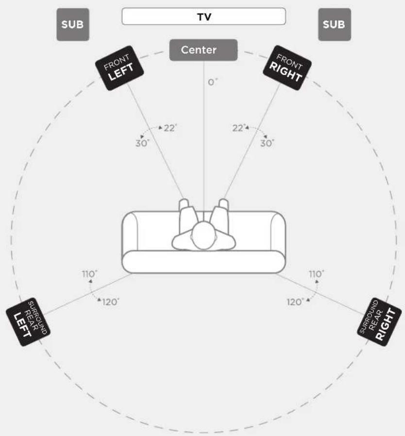
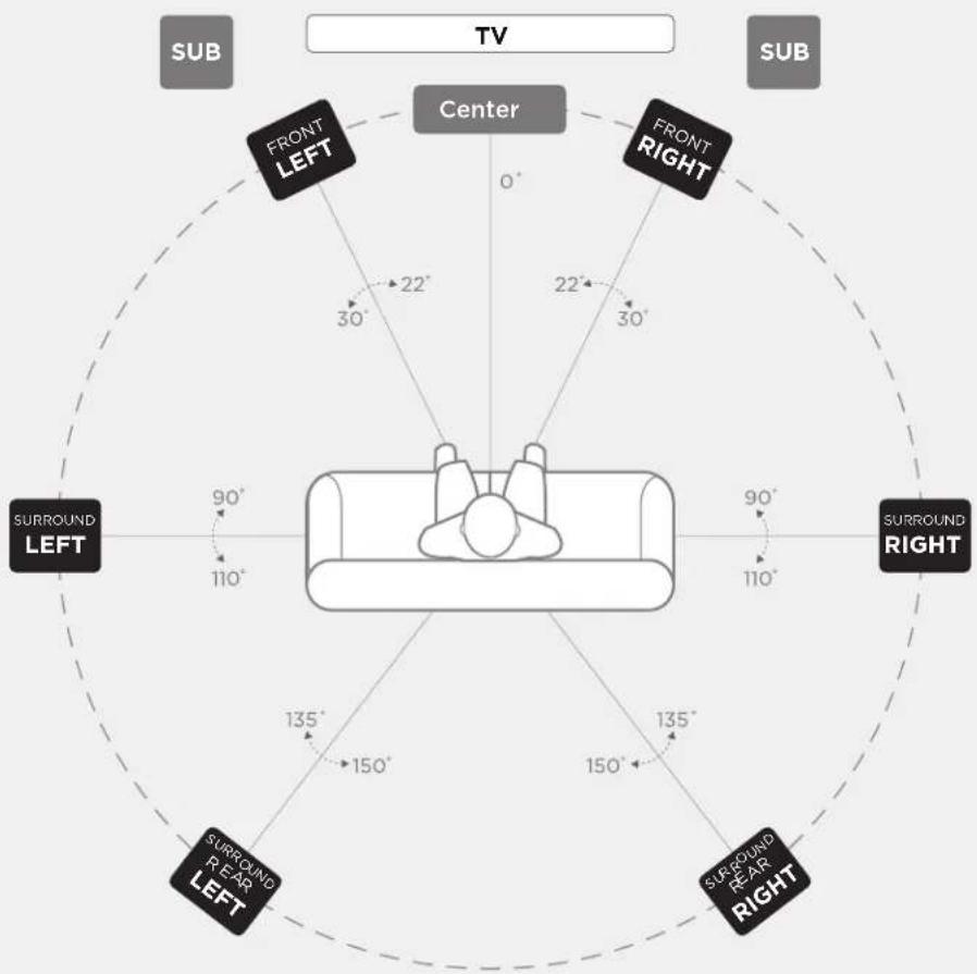
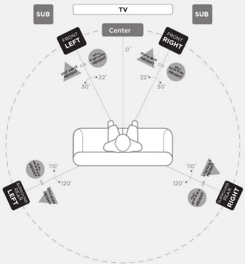
Note: Your Reserve Series speakers are compatible with basic/advanced 2.0, 2.1, 3.1, 5.1, 7.1 and 9.1 surround setups (optional subwoofer shown in graphic) and all Atmos setups (ex. 5.1.2, 5.1.4, 7.1.4, 7.1.6).
Listening in 5.2 Surround
You can use the Reserve Series speakers as rear surround speakers in a Polk Audio home theater surround system. Ideal rear channel surround speaker placement is along a side wall, slightly behind and above the listening position.
Note: If you cannot place rear surrounds along the side walls, position them along the rear wall above the listening position.
Listening in 7.1 Surround
Enjoy added depth to your surround sound experience with four rear surround speakers instead of two.
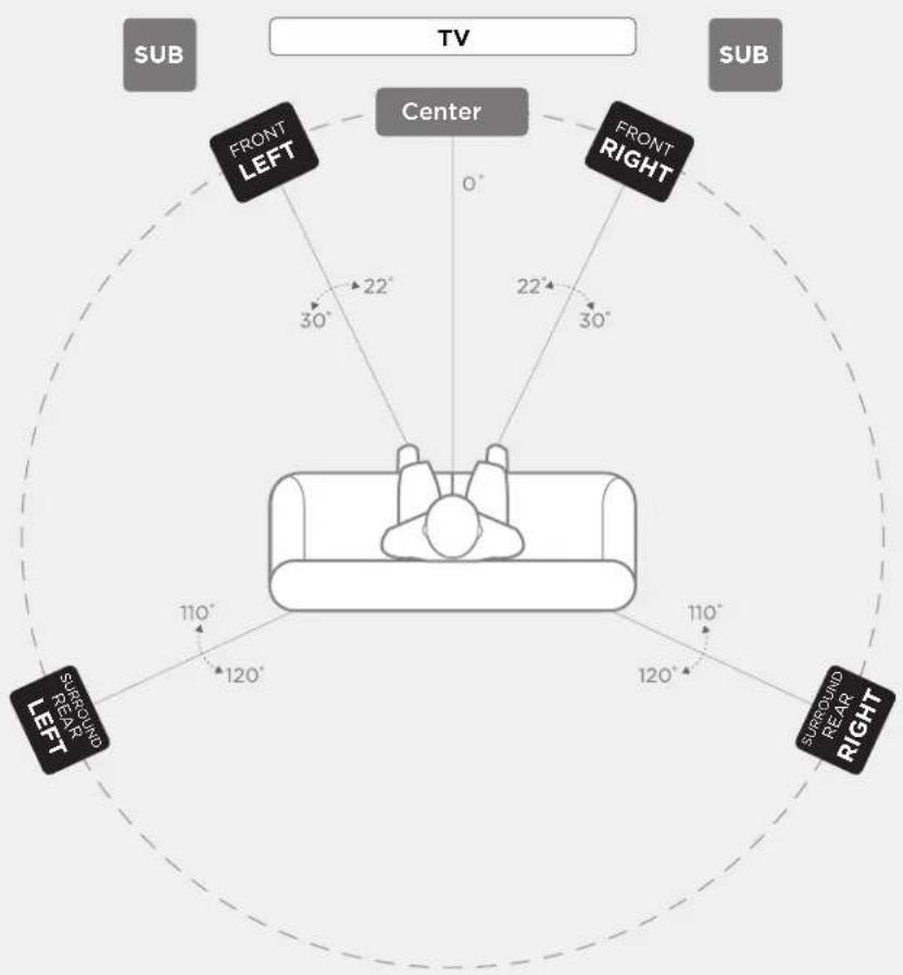
DOLBY ATMOS® 5.2 Configuration
SPEAKER PLACEMENT IN LISTENING AREA
text_image
TV SUB FRONT LEFT Center 0° 22° 22° 30° 30° FRONT RIGHT SUBROUND REAR RIGHT SURROUND REAR LEFT 110° 120° 110° 120°Primary Speakers
Front (L/R)
Surround Rear (L/R)

R100

R200
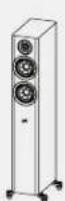
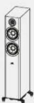
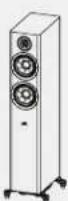
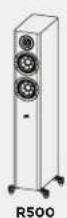
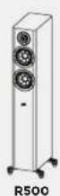
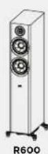
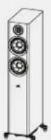
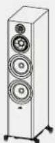
R500

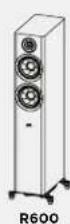
R600
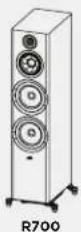
R700
PRIMARY
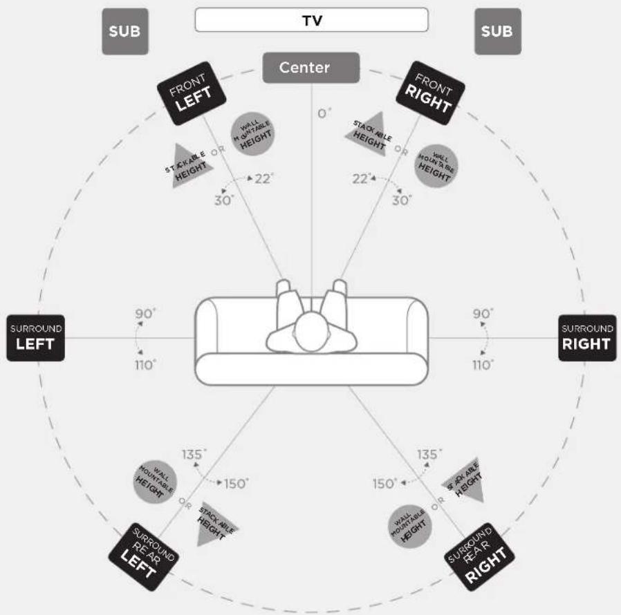
DOLBY ATMOS® 5.2.4 Configuration
SPEAKER PLACEMENT IN LISTENING AREA

flowchart
graph TD
    A["Center"] --> B["FRONT LEFT"]
    A --> C["FRONT RIGHT"]
    A --> D["SURROUND REAR LEFT"]
    A --> E["SURROUND REAR RIGHT"]
    B --> F["STACKABLE HEIGHT"]
    C --> G["STACKABLE HEIGHT"]
    D --> H["STACKABLE HEIGHT"]
    E --> I["STACKABLE HEIGHT"]
    F --> J["30°"]
    G --> K["22°"]
    H --> L["30°"]
    I --> M["120°"]
    J --> N["110°"]
    K --> O["110°"]
    L --> P["120°"]
    M --> Q["120°"]
    N --> R["120°"]
    O --> S["120°"]
    P --> T["120°"]
    Q --> U["120°"]
    R --> V["120°"]
    S --> W["120°"]
    T --> X["120°"]
    U --> Y["120°"]
    V --> Z["120°"]
    W --> AA["120°"]
    X --> AB["120°"]
    Y --> AC["120°"]
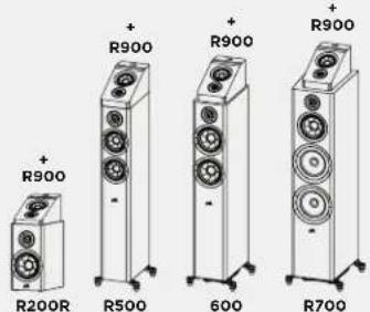
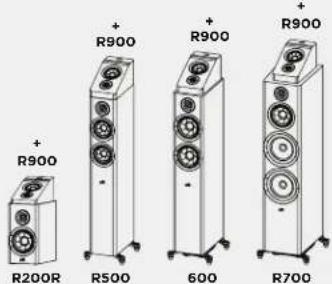
Primary Speakers
Front (L/R)
Surround Rear (L/R)


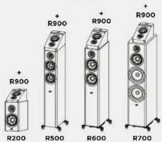
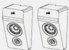
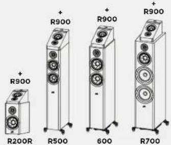
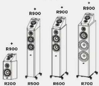
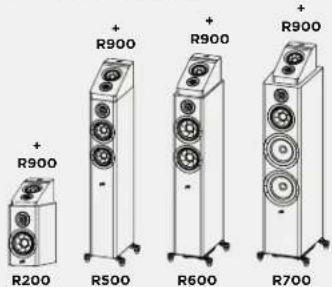
Stackable Height Option
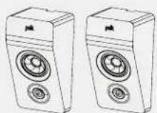
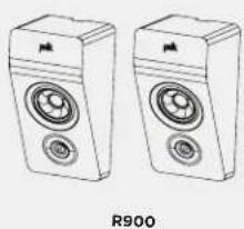
Add R900 on top of Front (L/R) and Surround Rear (L/R)
text_image
+ R900 R200R + R900 R500 + R900 600 + R900 R700Wall Mountable
Height Option
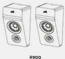
Mount R900 above Front (L/R) and Surround Rear (L/R)
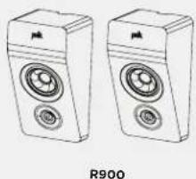
natural_image
Line drawing of two speakers with circular buttons and speaker heads, labeled R900 (no text or symbols on devices)


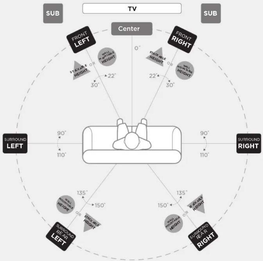
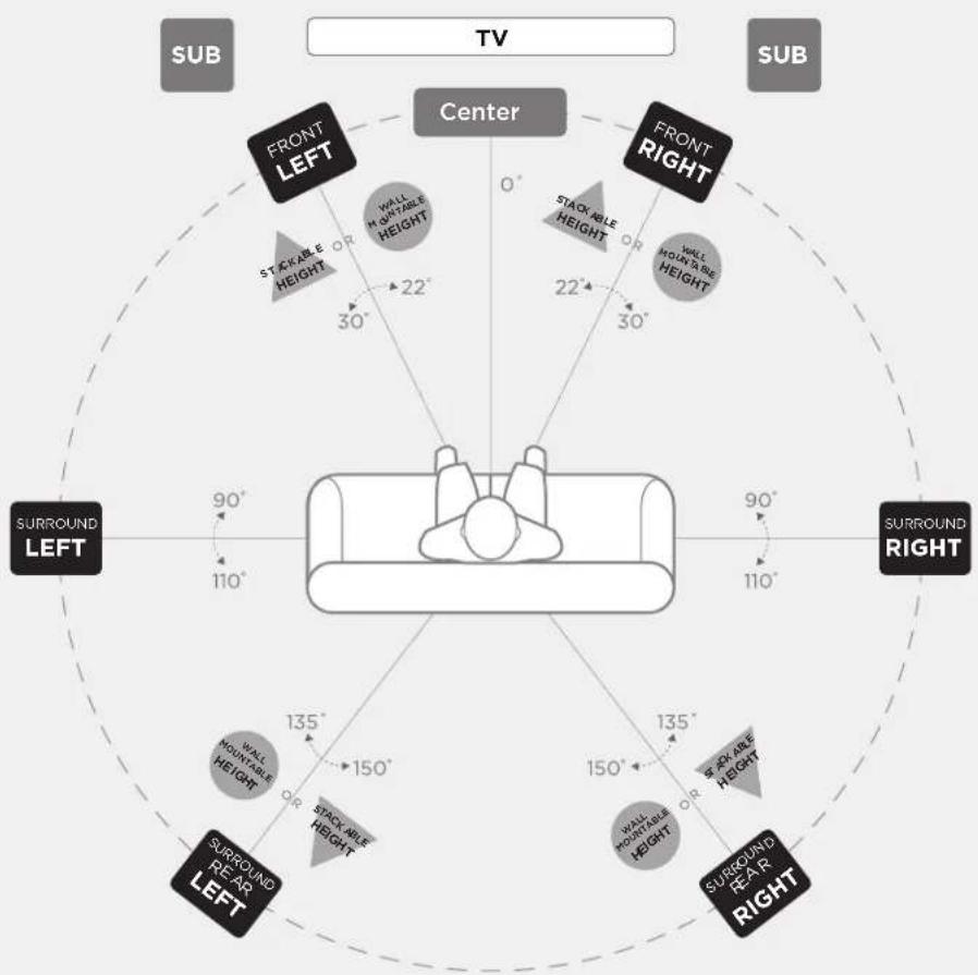
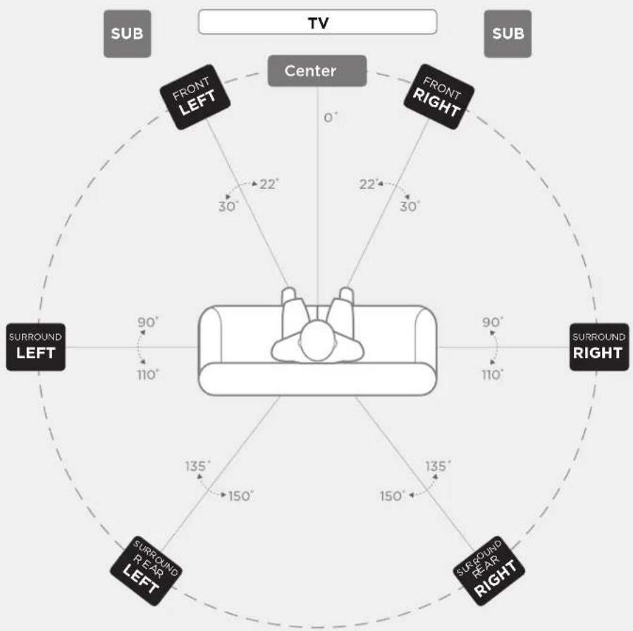
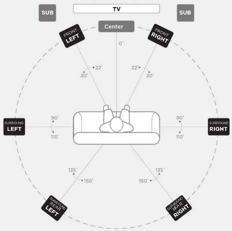
DOLBY ATMOS® 7.2 Configuration
SPEAKER PLACEMENT IN LISTENING AREA

text_image
TV SUB FRONT LEFT Center 0° 22° 30° 22° 30° FRONT RIGHT SURROUND LEFT 90° 110° 135° 150° 150° 135° 110° 90° SURROUND RIGHT SURROUND LEFT SURROUND RIGHTPrimary Speakers
Front (L/R)
Surround (L/R)
Surround Rear (L/R)

R100

R500R200 R600
R700

DOLBY ATMOS® 7.2.4 Configuration
SPEAKER PLACEMENT IN LISTENING AREA
flowchart
graph TD
    A["Center"] --> B["FRONT LEFT"]
    A --> C["FRONT RIGHT"]
    A --> D["SURROUND LEFT"]
    A --> E["SURROUND RIGHT"]
    A --> F["SURROUND REAR LEFT"]
    A --> G["SURROUND REAR RIGHT"]
    B --> H["STICKABLE HEIGHT 30°"]
    C --> I["STICKABLE HEIGHT 22°"]
    D --> J["STICKABLE HEIGHT 110°"]
    E --> K["STICKABLE HEIGHT 90°"]
    F --> L["STICKABLE HEIGHT 150°"]
    G --> M["STICKABLE HEIGHT 150°"]
    H --> N["WALL MOUNTABLE HEIGHT 22°"]
    I --> O["WELL MOUNTABLE HEIGHT 30°"]
    J --> P["WALL MOUNTABLE HEIGHT 150°"]
    K --> Q["WALL MOUNTABLE HEIGHT 150°"]
    L --> R["WALL MOUNTABLE HEIGHT 135°"]
    M --> S["WALL MOUNTABLE HEIGHT 135°"]
    N --> T["TV"]
    O --> U["TV"]
    P --> V["TV"]
    Q --> W["TV"]
    R --> X["TV"]
    S --> Y["TV"]
    T --> Z["TV"]
    U --> AA["TV"]
    V --> AB["TV"]
Primary Speakers
Front (L/R)
Surround (L/R)
Surround Rear (L/R)

R100

R200

R500

R600

R700
Stackable Height Option
Add R900 on top of Front (L/R), and Surrounds (L/R)

text_image
+ R900 R200 + R900 R500 + R900 R600 + R900 R700Wall Mountable Height Option
Mount R900 above Front (L/R), and Surrounds (L/R)

R900
PRIMARY


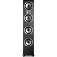
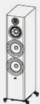
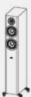
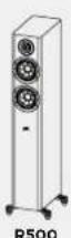
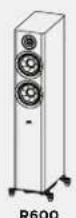
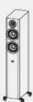
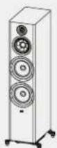
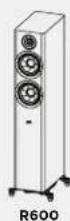
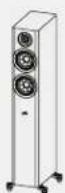
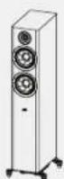
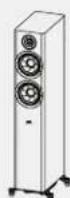
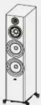
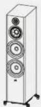
Floor-Standing Loudspeakers*
| Reserve Series Specifications | R500 | R600 R700 | |
| Tweeter | 1 in (25 mm) Pinnacle ring radiator | 1 in (25 mm) Pinnacle ring radiator | 1 in (25 mm) Pinnacle ring radiator |
| Mid-range/mid-bass | Two 5-1/4 in (133 mm) Turbine cones | Two 6.5 in (165 mm) Turbine cones | 6.5 in (165 mm) Turbine cone |
| Woofers/subwoofers --- Two 8 in (203 mm) woofers | |||
| Overall frequency response 32 Hz-50 kHz 30 Hz-50 kHz 30 Hz-50 kHz | |||
| Frequency response (-3 dB limits) | 49 Hz-38 kHz | 38 Hz-38 kHz | 38 Hz-38 kHz |
| Recommended amplifier power | 25-200W | 25-200W | 20-300W |
| Amplifier output compatibility | 8Ω / 6Ω / 4Ω | 8Ω / 6Ω / 4Ω | 8Ω / 6Ω / 4Ω |
| Minimum impedance | 3.9Ω | 4.0Ω | 3.6Ω |
| Sensitivity (2.83V/1m) | 87 dB | 87.5 dB SPL | 88 dB SPL |
| Crossover Frequency | |||
| Tweeter/mid-range | 2500 Hz | 2700 Hz | 2700 Hz |
| Mid-range/mid-bass --- 350 | |||
| Dimensions and Weight Attributes | |||
| Product dimensions (W x H x D)(greatest overall depth, grille) | 10.1 x 41.1 x 13.7 in255.4 x 1044.5 x 348.8 mm | 11.0 x 41.9 x 15.0 in280.7 x 1063.8 x 381.6 mm | 12.6 x 45.0 x 16.9 in320.7 x 1143.8 x 428.3 mm |
| Product weight | 39.0 lbs/17.7 kg | 47.3 lbs/21.5 kg | 79.1 lbs/35.9 kg |
| Shipping weight | 49.6 lbs/22.5 kg | 58.2 lbs/26.4 kg | 94.4 lbs/42.8 kg |
| Cabinetry | |||
| Mid-range enclosure type | --- Sealed | ||
| Mid-bass/woofer enclosure type | Rear ETF port | Floor-firing power port with ETF | Floor-firing power port with ETF |
| Available finishes | Black/brown/white | Black/brown/white | Black/brown |
| Feet | Spike and rubber feet | Spike and rubber feet | Spike and rubber feet |
| Binding posts | Single nickel-plated, 5-way | Single nickel-plated, 5-way | Dual nickel-plated, 5-way |
| Accessories | |||
| Designed for R900 speaker | Yes | Yes | Yes |
| Certifications (non-safety and regulatory) | |||
| Hi-res certified | Yes | Yes | Yes |
| IMAX certified | Yes | Yes | Yes |
*Subject to change without notice.
Center Channel Speakers*
| Reserve Series Specifications | R300 R350 R400 | ||
| Tweeter | 1 in (25 mm) Pinnacle ring radiator | 1 in (25 mm) Pinnacle ring radiator | 1 in (25 mm) Pinnacle ring radiator |
| Mid-range/mid-bass | Two 5.25 in (133 mm) Turbine cones | Four 4 in (102 mm) Turbine cones | Two 6.5 in (165 mm) Turbine cones |
| Woofers/subwoofers -- --- | |||
| Overall frequency response 45 Hz-50 kHz 50 Hz-50 kHz 36 Hz-50 kHz | |||
| Frequency response (-3 dB limits) | 65 Hz-38 kHz | 75 Hz-38 kHz | 48 Hz-38 kHz |
| Recommended amplifier power | 30-200 W | 25-200 W | 20-200 W |
| Amplifier output compatibility | 8Ω / 6Ω / 4Ω | 8Ω / 6Ω / 4Ω | 8Ω / 6Ω / 4Ω |
| Minimum impedance | 3.8Ω | 3.9Ω | 4.1Ω |
| Sensitivity (2.83V/1m) | 86.5dB | 87 dB SPL | 89 dB SPL |
| Crossover Frequency | |||
| Tweeter/mid-range | 2200 Hz | 2700 Hz | 2500 Hz |
| Mid-range/mid-bass -- 1400 | -- | ||
| Dimensions and Weight Attributes | |||
| Product dimensions (W x H x D)(greatest overall depth, grille) | 19.0 x 6.8 x 8.9 in482.6 x 172 x 226.5 mm | 30.0 x 5.5 x 7.4 in762 x 141 x 187.5 mm | 24.2 x 7.8 x 13.8 in615 x 196.6 x 350 mm |
| Product weight | 16.8 lbs/7.6 kg | 20.0 lbs/9 kg | 32.8 lbs/14.9 kg |
| Shipping weight | 19.8 lbs/9 kg | 23.7 lbs/10.8 kg | 39.5 lbs/17.9 kg |
| Cabinetry | |||
| Mid-range enclosure type | --- -- | ||
| Mid-bass/woofer enclosure type | Sealed | Sealed | Dual rear ETF ports |
| Available finishes | Black/brown/white | Black/brown/white | Black/brown |
| Feet | Rubber feet | Rubber feet | Rubber feet |
| Binding posts | Single nickel-plated, 5-way | Single nickel-plated, 5-way | Single nickel-plated, 5-way |
| Accessories | |||
| Designed for R900 speaker | n/a | n/a | n/a |
| Certifications (non-safety and regulatory) | |||
| Hi-res certified | Yes | Yes | Yes |
| IMAX certified | No | No | Yes |
*Subject to change without notice.
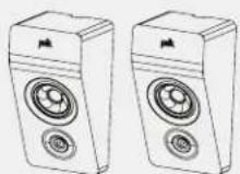
Bookshelf Speakers*
| Reserve Series Specifications | R100 R200 | |
| Tweeter 1 in (25 mm) Pinnacle ring radiator 1 in (25 mm) Pinnacle ring radiator | ||
| Mid-range/mid-bass 5.25 in (133 mm) Turbine cone 6.5 in (165 mm) Turbine cone | ||
| Woofers/subwoofers -- -- | ||
| Overall frequency response 44 Hz-50 kHz 39 Hz-50 kHz | ||
| Frequency response (-3 dB limits) 58 Hz-38 kHz 51 Hz-38 kHz | ||
| Recommended amplifier power 30-150 W 30-200 W | ||
| Amplifier output compatibility | 8Ω / 6Ω / 4Ω | 8Ω / 6Ω / 4Ω |
| Minimum impedance | 3.6Ω | 3.8Ω |
| Sensitivity (2.83V/1m) 86 dB SPL | 86 dB SPL | |
| Crossover Frequency | ||
| Tweeter/mid-range | 2700 Hz | 3000 Hz |
| Mid-range/mid-bass -- -- | ||
| Dimensions and Weight Attributes | ||
| Product dimensions (W x H x D)(greatest overall depth, grille) | 6.5 x 12.8 x 10.2 in166 x 324 x 259.5 mm | 7.5 x 14.1 x 13.9 in190 x 359 x 353.8 mm |
| Product weight | 12.2 lbs/5.5 kg | 19.1 lbs/8.7 kg |
| Shipping weight | 28.4 lbs/12.9 kg | 43.4 lbs/19.7 kg |
| Cabinetry | ||
| Mid-range enclosure type | -- -- | |
| Mid-bass/woofer enclosure type | Rear ETF port | Rear ETF port |
| Available finishes | Black/brown/white | Black/brown/white |
| Feet | Rubber feet | Rubber feet |
| Binding posts | Single nickel-plated, 5-way | Single nickel-plated, 5-way |
| Accessories | ||
| Designed for R900 speaker | No | Yes |
| Certifications (non-safety and regulatory) | ||
| Hi-res certified | Yes | Yes |
| IMAX certified | No | No |
*Subject to change without notice.
Caring for Your Reserve Loudspeakers
Enclosure Finish
Your Reserve loudspeakers are finished with a premium vinyl. To clean the panels, use a soft dry cloth. You may use furniture polish if needed. Never use harsh detergents or cleaning fluids.
Note: Do not use any petroleum-based cleaners or solvents on the loudspeaker cabinets.
- Do not use furniture polish on black gloss lacquer.
- Clean black lacquer veneer with a damp cloth.
Dusting the Baffle
Use a can of compressed air for the grille and/or baffle to dust. Use a "computer keyboard" vacuum (only on the grille, not the baffle).
Limited 5-Year Warranty
Polk Audio, Inc. warrants to the original purchaser only that this Polk Audio Loudspeaker Product (the "Product") will be free from defects in materials and workmanship for a period of five (5) years from the date of original retail purchase from a Polk Audio Authorized Dealer. However, this Warranty will automatically terminate prior to the expiration of the five (5) years if the original retail purchaser sells or otherwise transfers the Product to any other party. The original retail purchaser shall hereinafter be referred to as "you." To allow Polk Audio to offer the best possible warranty service, please fill out the Product Registration Card(s) and send it to the Factory, at the address provided on the Product Cards(s) within ten (10) days of the date of purchase.
Defective Products must be shipped, together with proof of purchase, prepaid insured to the Polk Audio Authorized Dealer from whom you purchased the Product, or an authorized service center. Products must be shipped in the original shipping container or its equivalent; in any case the risk of loss or damage in transit is to be borne by you. If upon examination at the Factory or Polk Audio Authorized Dealer it is determined that the unit was defective in materials or workmanship at any time during this Warranty period, Polk Audio or the Polk Audio Authorized Dealer will, at its option, repair or replace this Product at no additional charge, except as set forth below. All replaced parts and Products become the property of Polk Audio. Products replaced or repaired under this warranty will be returned to you, within a reasonable time, freight prepaid.
This warranty does not include service or parts to repair damage caused by accident, disaster, misuse, abuse, negligence, inadequate packing or shipping procedures, commercial use, voltage inputs in excess of the rated maximum of the unit, cosmetic appearance of cabinetry not directly attributable to defect in materials or workmanship, or service, repair, or modification of the Product which has not been authorized or approved by Polk Audio. This warranty shall terminate if the Serial number on the Product has been removed, tampered with or defaced. This warranty is in lieu of all other expressed Warranties. If this Product is defective in materials or workmanship as warranted above, your sole
remedy shall be repair or replacement as provided above. In no event will Polk Audio, Inc. be liable to you for any incidental or consequential damages arising out of the use or inability to use the Product, even if Polk Audio, Inc. or a Polk Audio Authorized Dealer has been advised of the possibility of such damages, or for any claim by any other party. Some states do not allow the exclusion or limitation of consequential damages, so the above limitation and exclusion may not apply to you. All implied warranties on this Product are limited to the duration of this expressed Warranty. Some states do not allow limitation on how long an implied Warranty lasts, so the above limitations may not apply to you. This Warranty gives you specific legal rights, and you also may have other rights which vary from state to state. This Warranty applies only to Products purchased in the United States of America, its possessions, and U.S. and NATO armed forces exchanges and audio clubs. The Warranty terms and conditions applicable to Products purchased in other countries are available from the Polk Audio Authorized Distributors in such countries.
polk
Sound United, LLC
5541 Fermi Court
Carlsbad, CA 92008 USA
EU Importer: D&M Europe B.V.
Eindhoven, The Netherlands
+1 800-377-7655
www.polkaudio.com
email: polkcs@polkaudio.com
twitter: @polkaudio
©2021 POLK AUDIO
All Rights Reserved.
Contenu
Assistance ou service technique
text_image
Warning sign and magnified view of a mechanical component with hand impact symbolnatural_image
Four technical illustrations of mechanical connectors with no visible text or symbolsConnecteurs
text_image
High Frequency Amplifier - L + Upper Input - L + Lower Input - L + Low Frequency Amplifier - R + Upper Input - R + Lower Input - R +(Figure 2)
Gestion des basses
natural_image
Technical line drawing of a vertical cylindrical device with attached base and mounting feet, showing internal mechanical assembly (no text or symbols)Primary Speakers
Front (L/R)
Surround Rear (L/R)


Stackable Height Option
Add R900 on top of Front (L/R) and Surround Rear (L/R)

text_image
+ R900 + R900 + R900 + R900 R200R R500 600 R700Wall Mountable
Height Option
Mount R900 above Front (L/R) and Surround Rear (L/R)

natural_image
Line drawing of two identical speaker units with circular buttons and a label R900 below (no text or symbols on the devices themselves)


Configuration DOLBY ATMOS® 7.2
POSITIONNEMENT DES ENCEINTES DANS LA ZONE D'ÉCOUTE

text_image
TV SUB FRONT LEFT Center 0° 22° 30° 22° 30° FRONT RIGHT SURROUND LEFT 90° 110° 135° 150° 150° 135° 110° 90° SURROUND RIGHT SURROUND LEFT SURROUND RIGHTPrimary Speakers
Front (L/R)
Surround (L/R)
Surround Rear (L/R)

R100


R500R200 R600

R700

Configuration DOLBY ATMOS® 7.2.4
POSITIONNEMENT DES ENCEINTES DANS LA ZONE D'ÉCOUTE
flowchart
graph TD
    A["Center"] --> B["FRONT LEFT"]
    A --> C["FRONT RIGHT"]
    A --> D["SURROUND LEFT"]
    A --> E["SURROUND RIGHT"]
    B --> F["STACKABLE HEIGHT"]
    C --> G["STACK ABILE HEIGHT"]
    D --> H["SURROUND REAR LEFT"]
    E --> I["SURROUND REAR RIGHT"]
    F --> J["STACKABLE HEIGHT"]
    G --> K["STACK ABILE HEIGHT"]
    H --> L["SURROUND REAR LEFT"]
    I --> M["SURROUND REAR RIGHT"]
    J --> N["30°"]
    K --> O["22°"]
    L --> P["110°"]
    M --> Q["90°"]
    N --> R["0°"]
    O --> S["30°"]
    P --> T["110°"]
    Q --> U["150°"]
    R --> V["150°"]
    S --> W["135°"]
    T --> X["135°"]
Primary Speakers
Front (L/R)
Surround (L/R)
Surround Rear (L/R)

R100

R200

R500

R600

R700
Stackable Height Option
Add R900 on top of Front (L/R), and Surrounds (L/R)

text_image
+ R900 R200 + R900 R500 + R900 R600 + R900 R700Wall Mountable Height Option
Mount R900 above Front (L/R), and Surrounds (L/R)

R900
PRIMARY


text_image
Warning sign and magnified view of a device with hand impact symbolhttps://www.polkaudio.com/declaration-of-conformance"
Sound United, LLC
5541 Fermi Court
Carlsbad, CA 92008, USA
natural_image
Four technical illustrations of a mechanical connector with threaded ports and a central pin (no text or symbols)Steckverbinder
text_image
RECHTS VORNEtext_image
High Frequency Amplifier - L + Upper Input - L + Lower Input - L + Low Frequency Amplifier (Abbildung 2) - R + Upper Input - R + Lower Input - R +Bass-Management
natural_image
Technical line drawing of a vertical cylindrical device with attached base and sensor points, showing internal mechanical assembly (no text or symbols)Primary Speakers
Front (L/R)
Surround Rear (L/R)

R100

R200
R500

R600

R700
Stackable Height Option
Add R900 on top of Front (L/R) and Surround Rear (L/R)

text_image
+ R900 R200R + R900 R500 + R900 600 + R900 R700Wall Mountable
Height Option
Mount R900 above Front (L/R) and Surround Rear (L/R)
R900
PRIMARY


Add R900 on top of Front (L/R), and Surrounds (L/R)

text_image
+ R900 R200 + R900 R500 + R900 R600 + R900 R700Wall Mountable Height Option
Mount R900 above Front (L/R), and Surrounds (L/R)

R900
PRIMARY


Standlautsprecher*
text_image
Warning sign and magnified view of a device with hand contact and spiral patternnatural_image
Four identical mechanical component diagrams showing different mounting or fitting configurations (no text or symbols)Connectors
natural_image
Line drawing of a vertical rectangular device with a close-up inset showing a small mechanical component (no text or symbols)Luisteren in 5.2 surround
Luisteren in 7.1 surround
Primary Speakers
Front (L/R)
Surround Rear (L/R)


Stackable Height Option
Add R900 on top of Front (L/R) and Surround Rear (L/R)

text_image
+ R900 R200R + R900 R500 + R900 600 + R900 R700Wall Mountable
Height Option
Mount R900 above Front (L/R) and Surround Rear (L/R)

natural_image
Illustration of two identical speaker speakers with circular buttons, labeled R900 (no text or symbols on devices)


DOLBY ATMOS® 7.2 Configuratie
PLAATSING VAN DE LUIDSPREKERS IN HET LUISTERGEBIED
text_image
TV SUB FRONT LEFT Center 0° 22° 30° 22° 30° FRONT RIGHT SURROUND LEFT 90° 110° 135° 150° 150° 135° 110° 90° SURROUND RIGHT SURROUND LEFT SURROUND RIGHTPrimary Speakers
Front (L/R)
Surround (L/R)
Surround Rear (L/R)

R100

R500R200 R600

R700

DOLBY ATMOS® 7.2.4 Configuratie
PLAATSING VAN DE LUIDSPREKERS IN HET LUISTERGEBIED
flowchart
graph TD
    A["TV"] --> B["Center"]
    B --> C["FRONT LEFT"]
    B --> D["FRONT RIGHT"]
    B --> E["SURROUND LEFT"]
    B --> F["SURROUND RIGHT"]
    B --> G["SURROUND REAR LEFT"]
    B --> H["SURROUND REAR RIGHT"]
    B --> I["STICKABLE HEIGHT 30°"]
    B --> J["STICKABLE HEIGHT 22°"]
    B --> K["WALL MOUNTABLE HEIGHT 150°"]
    B --> L["STICKABLE HEIGHT 135°"]
    B --> M["WALL MOUNTABLE HEIGHT 150°"]
    B --> N["SURROUND REAR LEFT 90°"]
    B --> O["SURROUND REAR RIGHT 90°"]
    style A fill:#f9f,stroke:#333
    style B fill:#ccf,stroke:#333
    style C fill:#cfc,stroke:#333
    style D fill:#cfc,stroke:#333
    style E fill:#fcc,stroke:#333
    style F fill:#fcc,stroke:#333
    style G fill:#fcc,stroke:#333
    style H fill:#fcc,stroke:#333
    style I fill:#fcc,stroke:#333
    style J fill:#fcc,stroke:#333
    style K fill:#fcc,stroke:#333
    style L fill:#fcc,stroke:#333
    style M fill:#fcc,stroke:#333
    style N fill:#fcc,stroke:#333
    style O fill:#fcc,stroke:#333
Primary Speakers
Front (L/R)
Surround (L/R)
Surround Rear (L/R)

R100

R200
R500
R600
R700
Stackable Height Option
Add R900 on top of Front (L/R), and Surrounds (L/R)
text_image
+ R900 R200 + R900 R500 + R900 R600 + R900 R700Wall Mountable Height Option
Mount R900 above Front (L/R), and Surrounds (L/R)

R900
PRIMARY


text_image
Warning sign and magnified view of a device with hand impact symbolnatural_image
Four technical illustrations of a mechanical connector with threaded ports and a central shaft, shown in different orientations (no text or symbols present)Conectores
natural_image
Technical line drawing of a vertical cylindrical device with attached mechanical components, showing a close-up inset of the component (no text or symbols present)Primary Speakers
Front (L/R)
Surround Rear (L/R)


Stackable Height Option
Add R900 on top of Front (L/R) and Surround Rear (L/R)

text_image
+ R900 + R900 + R900 + R900 R200R R500 600 R700Wall Mountable
Height Option
Mount R900 above Front (L/R) and Surround Rear (L/R)

natural_image
Illustration of two identical speaker speakers with circular buttons, labeled R900 (no text or symbols on devices)


Add R900 on top of Front (L/R), and Surrounds (L/R)

text_image
+ R900 R200 + R900 R500 + R900 R600 + R900 R700Wall Mountable Height Option
Mount R900 above Front (L/R), and Surrounds (L/R)

R900
PRIMARY


Altavoces de suelo*
text_image
Warning sign and magnified view of a device with hand contact and spiral patternhttps://www.polkaudio.com/declarations-of-conformity
Sound United, LLC
5541 Fermi Court
Carlsbad, CA 92008
Kontakt w UE: Sound United Europe, A division of D&M Europe B.V. Beemdstraat 11, 5653 MA Eindhoven, Holandia
natural_image
Four technical illustrations of a mechanical connector with threaded ports and a central pin (no text or symbols)Złącza
natural_image
Technical line drawing of a vertical cylindrical device with attached base and sensor points, showing internal mechanical assembly (no text or symbols)Primary Speakers
Front (L/R)
Surround Rear (L/R)

R100

R200
R500
R600

R700

Konfiguracja DOLBY ATMOS® 5.2.4
ROZMIESZCZENIE GŁOŚNIKÓW W MIEJSCU ODSŁUCHU

flowchart
graph TD
    A["Center"] --> B["FRONT LEFT"]
    A --> C["FRONT RIGHT"]
    A --> D["SURROUND REAR RIGHT"]
    B --> E["STACKABLE HEIGHT 30°"]
    C --> F["STACKABLE HEIGHT 22°"]
    D --> G["SURROUND RELA LEFT 110°"]
    D --> H["SURROUND RELA RIGHT 120°"]
    E --> I["WALL MOUNTABLE HEIGHT 22°"]
    F --> J["WALL MOUNTABLE HEIGHT 30°"]
    G --> K["WALL MOUNTABLE HEIGHT 110°"]
    style A fill:#f9f,stroke:#333
    style B fill:#ccf,stroke:#333
    style C fill:#ccf,stroke:#333
    style D fill:#ccf,stroke:#333
Primary Speakers
Front (L/R)
Surround Rear (L/R)

R100

R200

R500
R600
R700
Stackable Height Option
Add R900 on top of Front (L/R) and Surround Rear (L/R)

text_image
+ R900 R200R + R900 R500 + R900 600 + R900 R700Wall Mountable
Height Option
Mount R900 above Front (L/R) and Surround Rear (L/R)

R900
PRIMARY


Konfiguracja DOLBY ATMOS® 7.2
ROZMIESZCZENIE GŁOŚNIKÓW W MIEJSCU ODSŁUCHU

text_image
TV SUB FRONT LEFT Center 0° 22° 30° 22° 30° FRONT RIGHT SURROUND LEFT 90° 110° 135° 150° 150° 135° 110° 90° SURROUND RIGHT SURROUND LEFT SURROUND RIGHTPrimary Speakers
Front (L/R)
Surround (L/R)
Surround Rear (L/R)

R100


R500R200 R600


R700
PRIMARY
Konfiguracja DOLBY ATMOS® 7.2.4
ROZMIESZCZENIE GŁOŚNIKÓW W MIEJSCU ODSŁUCHU

flowchart
graph TD
    A["Center"] --> B["FRONT LEFT"]
    A --> C["FRONT RIGHT"]
    A --> D["SURROUND LEFT"]
    A --> E["SURROUND RIGHT"]
    B --> F["STICKABLE HEIGHT 30°"]
    C --> G["STICKABLE HEIGHT 22°"]
    D --> H["SURROUND REAR LEFT 110°"]
    E --> I["SURROUND REAR RIGHT 110°"]
    F --> J["WALL MOUNTABLE HEIGHT 22°"]
    G --> K["WELL MOUNTABLE HEIGHT 30°"]
    H --> L["WALL MOUNTABLE HEIGHT 150°"]
    I --> M["WALL MOUNTABLE HEIGHT 150°"]
    J --> N["STICKABLE HEIGHT 90°"]
    K --> O["STICKABLE HEIGHT 90°"]
    L --> P["STICKABLE HEIGHT 90°"]
    M --> Q["STICKABLE HEIGHT 90°"]
Primary Speakers
Front (L/R)
Surround (L/R)
Surround Rear (L/R)

R100

R200

R500

R600

R700
Stackable Height Option
Add R900 on top of Front (L/R), and Surrounds (L/R)

text_image
+ R900 R200 + R900 R500 + R900 R600 + R900 R700Wall Mountable Height Option
Mount R900 above Front (L/R), and Surrounds (L/R)
R900
PRIMARY


Głośniki podłogowe*
text_image
Warning sign and magnified view of a device with hand contact and spiral coil, indicating hazard or hazard.text_image
Warning sign and magnified view of a device with hand contact and spiral coil, indicating hazard or hazard.natural_image
Four technical illustrations of a mechanical connector with threaded ports and a central pin (no text or symbols)text_image
High Frequency Amplifier - L + Upper Input - L + Lower Input - L + Low Frequency Amplifier - R + Upper Input - R + Lower Input - R +(Рисунок 2)
Управление басами
natural_image
Technical line drawing of a vertical cylindrical device with a close-up inset showing internal components (no text or symbols)Primary Speakers
Front (L/R)
Surround Rear (L/R)

R100

R200

R500

R600

R700
Stackable Height Option
Add R900 on top of Front (L/R) and Surround Rear (L/R)
text_image
+ R900 + R900 + R900 + R900 R200R R500 600 R700Wall Mountable
Height Option
Mount R900 above Front (L/R) and Surround Rear (L/R)

R900
PRIMARY


Add R900 on top of Front (L/R), and Surrounds (L/R)
text_image
+ R900 R200 + R900 R500 + R900 R600 + R900 R700Wall Mountable Height Option
Mount R900 above Front (L/R), and Surrounds (L/R)
R900
PRIMARY


Напольные динамики*
text_image
Warning sign and magnified view of a mechanical component with hand contact and spiral coilnatural_image
Four identical mechanical component diagrams showing a cylindrical pin assembly, with no text or symbols present.Connettori
Bi-wiring (solo R700)
text_image
High Frequency Amplifier Upper Input Lower Input High Frequency Amplifier Upper Input Lower Input Upper Input Lower Input(Figura 2)
Gestione dei bassi
natural_image
Line drawing of a vertical shelf unit with a close-up inset showing the internal structure (no text or symbols)Primary Speakers
Front (L/R)
Surround Rear (L/R)


Stackable Height Option
Add R900 on top of Front (L/R) and Surround Rear (L/R)

text_image
+ R900 R200R + R900 R500 + R900 600 + R900 R700Wall Mountable
Height Option
Mount R900 above Front (L/R) and Surround Rear (L/R)

natural_image
Illustration of two identical speaker speakers with circular buttons, labeled R900 (no text or symbols on devices)


Add R900 on top of Front (L/R), and Surrounds (L/R)

text_image
+ R900 R200 + R900 R500 + R900 R600 + R900 R700Wall Mountable Height Option
Mount R900 above Front (L/R), and Surrounds (L/R)

R900
PRIMARY


Altoparlanti a pavimento*
text_image
Warning sign and magnified view of a device with hand impact symbolÅtervinning:
natural_image
Four technical line drawings of mechanical connectors or fittings, showing different mounting configurations (no text or symbols present)Anslutningar
natural_image
Line drawing of a vertical rectangular device with a close-up inset showing a mechanical component (no text or symbols)HÖGTALARENS PLACERING I LYSSNINGSOMRÅDET
text_image
TV SUB FRONT LEFT Center 0° 22° 30° 22° 30° FRONT RIGHT SUB SURROUND REAR RIGHT 110° 120° 110° 120°Primary Speakers
Front (L/R)
Surround Rear (L/R)

R100

R200

R500

R600
R700

Konfiguration av DOLBY ATMOS® 5.2.4
HÖGTALARENS PLACERING I LYSSNINGSOMRÅDET
flowchart
graph TD
    A["TV"] --> B["Center"]
    B --> C["FRONT LEFT"]
    B --> D["FRONT RIGHT"]
    B --> E["SURROUND REAR RIGHT"]
    B --> F["SURROUND RELA LEFT"]
    B --> G["SURROUND REAR HEIGHT"]
    B --> H["WALL MOUNTABLE HEIGHT"]
    B --> I["STACKABLE HEIGHT"]
    B --> J["STACKABLE HEIGHT"]
    B --> K["STACKABLE HEIGHT"]
    style A fill:#f9f,stroke:#333
    style B fill:#ccf,stroke:#333
    style C fill:#cfc,stroke:#333
    style D fill:#cfc,stroke:#333
    style E fill:#fcc,stroke:#333
    style F fill:#cff,stroke:#333
    style G fill:#ffc,stroke:#333
    style H fill:#ffc,stroke:#333
    style I fill:#ffc,stroke:#333
    style J fill:#ffc,stroke:#333
    style K fill:#ffc,stroke:#333
    style_L["STICKABLE HEIGHT"] --> M["30°"]
    L --> N["22°"]
    L --> O["0°"]
    L --> P["30°"]
    L --> Q["110°"]
    L --> R["120°"]
    L --> S["110°"]
    L --> T["120°"]
Primary Speakers
Front (L/R)
Surround Rear (L/R)


Stackable Height Option
Add R900 on top of Front (L/R) and Surround Rear (L/R)

text_image
+ R900 + R900 + R900 + R900 R200R R500 600 R700Wall Mountable
Height Option
Mount R900 above Front (L/R) and Surround Rear (L/R)

natural_image
Illustration of two identical speaker speakers with circular buttons, labeled R900 (no text or symbols on devices)


Konfiguration av DOLBY ATMOS® 7.2
HÖGTALARENS PLACERING I LYSSNINGSOMRÅDET

text_image
TV SUB FRONT LEFT Center 0° 22° 30° 22° 30° FRONT RIGHT SURROUND LEFT 90° 110° 135° 150° 150° 135° 110° 90° SURROUND RIGHT SURROUND LEFT SURROUND RIGHTPrimary Speakers
Front (L/R)
Surround (L/R)
Surround Rear (L/R)

R100


R500R200 R600


R700

Konfiguration av DOLBY ATMOS® 7.2.4
HÖGTALARENS PLACERING I LYSSNINGSOMRÅDET

flowchart
graph TD
    A["Center"] --> B["FRONT LEFT"]
    A --> C["FRONT RIGHT"]
    A --> D["SURROUND LEFT"]
    A --> E["SURROUND RIGHT"]
    B --> F["STICKABLE HEIGHT 30°"]
    C --> G["STICKABLE HEIGHT 22°"]
    D --> H["SURROUND REAR LEFT 110°"]
    E --> I["SURROUND REAR RIGHT 110°"]
    F --> J["STICKABLE HEIGHT 22°"]
    G --> K["STICKABLE HEIGHT 30°"]
    H --> L["SURROUND REAR LEFT 150°"]
    I --> M["SURROUND REAR RIGHT 150°"]
    J --> N["WALL MOUNTABLE HEIGHT 135°"]
    K --> O["WALL MOUNTABLE HEIGHT 150°"]
    L --> P["WALL MOUNTABLE HEIGHT 135°"]
    M --> Q["WALL MOUNTABLE HEIGHT 150°"]
    N --> R["TV Sub"]
    O --> S["TV Sub"]
Primary Speakers
Front (L/R)
Surround (L/R)
Surround Rear (L/R)

R100

R200

R500

R600

R700
Stackable Height Option
Add R900 on top of Front (L/R), and Surrounds (L/R)

text_image
+ R900 R200 + R900 R500 + R900 R600 + R900 R700Wall Mountable Height Option
Mount R900 above Front (L/R), and Surrounds (L/R)

R900
PRIMARY


Golvhögtalare*
text_image
Warning sign and magnified view of a device with hand impact symbolリサイクルに関する注意:
https://www.polkaudio.com/declarations-of-conformity
Sound United, LLC
5541 Fermi Court
Carlsbad, CA 92008
EUの連絡先: Sound United Europe, A division of D&M Europe B.V. Beemdstraat 11, 5653 MA Eindhoven, The Netherlands
捆包内容
次のものを同梱しています。
natural_image
Four technical illustrations of a mechanical connector with threaded ports and a central pin (no text or symbols)コネクター
natural_image
Technical line drawing of a vertical rectangular device with a close-up inset showing a mechanical component (no text or symbols)Primary Speakers
Front (L/R)
Surround Rear (L/R)

Stackable Height Option
Add R900 on top of Front (L/R) and Surround Rear (L/R)

text_image
+ R900 R200R + R900 R500 + R900 600 + R900 R700Wall Mountable
Height Option
Mount R900 above Front (L/R) and Surround Rear (L/R)
natural_image
Two identical 3D-rendered speaker units with circular buttons and a label R900 below (no text or symbols on the devices themselves)


DOLBY ATMOS® 7.2 Configuration
SPEAKER PLACEMENT IN LISTENING AREA
text_image
TV SUB FRONT LEFT Center 0° 22° 30° 22° 30° FRONT RIGHT SURROUND LEFT 90° 110° 135° 150° 150° 135° 110° 90° SURROUND RIGHT SURROUND LEFT SURROUND RIGHTPrimary Speakers
Front (L/R)
Surround (L/R)
Surround Rear (L/R)

R100


R500R200 R600


R700

DOLBY ATMOS® 7.2.4 Configuration
SPEAKER PLACEMENT IN LISTENING AREA

flowchart
graph TD
    A["Center"] --> B["FRONT LEFT"]
    A --> C["FRONT RIGHT"]
    A --> D["SURROUND LEFT"]
    A --> E["SURROUND RIGHT"]
    A --> F["SURROUND REAR LEFT"]
    A --> G["SURROUND REAR RIGHT"]
    H["STICKABLE HEIGHT"] --> I["0°"]
    J["STICKABLE HEIGHT"] --> K["22°"]
    L["STICKABLE HEIGHT"] --> M["30°"]
    N["STICKABLE HEIGHT"] --> O["110°"]
    P["STICKABLE HEIGHT"] --> Q["150°"]
    R["STICKABLE HEIGHT"] --> S["135°"]
    T["STICKABLE HEIGHT"] --> U["150°"]
    V["STICKABLE HEIGHT"] --> W["135°"]
    X["STICKABLE HEIGHT"] --> Y["150°"]
    Z["STICKABLE HEIGHT"] --> AA["135°"]
    AB["STICKABLE HEIGHT"] --> AC["150°"]
    AD["STICKABLE HEIGHT"] --> AE["135°"]
    AF["STICKABLE HEIGHT"] --> AG["150°"]
    AH["STICKABLE HEIGHT"] --> AI["135°"]
    AJ["STICKABLE HEIGHT"] --> AK["150°"]
    AL["STICKABLE HEIGHT"] --> AM["135°"]
    AN["STICKABLE HEIGHT"] --> AO["150°"]
    AP["STICKABLE HEIGHT"] --> AQ["135°"]
    AR["STICKABLE HEIGHT"] --> AS["150°"]
    AT["STICKABLE HEIGHT"] --> AU["135°"]
    AV["STICKABLE HEIGHT"] --> AW["150°"]
    AX["STICKABLE HEIGHT"] --> AY["135°"]
    AZ["STICKABLE HEIGHT"] --> BA["150°"]
    BB["SUB"] --> BC["TV"]
    BD["SUB"] --> BE["TV"]
    BF["SUB"] --> BG["TV"]
Primary Speakers
Front (L/R)
Surround (L/R)
Surround Rear (L/R)

R100

R200

R500
R600
R700
Stackable Height Option
Add R900 on top of Front (L/R), and Surrounds (L/R)

text_image
+ R900 R200 + R900 R500 + R900 R600 + R900 R700Wall Mountable Height Option
Mount R900 above Front (L/R), and Surrounds (L/R)

R900
PRIMARY


フロアスタンディングスピーカー *
Eindhoven, The Netherlands
+1 800-377-7655
www.polkaudio.com
メ - ル:polkcs@polkaudio.com
Twitterアカウント:@polkaudio
©2021 POLK AUDIO
All Rights Reserved.
目录
Expect Great Sound - Polk Reserve 品牌简介 2
安全说明 3
箱内物品清单 4
系统连接方式 4
Reserve 系列音箱定位.....5
Reserve 音箱保养 6
规格 7
Expect Great Sound - Polk Reserve 品牌简介
text_image
Warning sign and magnified view of a device with hand contact and spiral pattern使用说明
警告
natural_image
Four technical illustrations of a mechanical connector with threaded ports and a central pin (no text or symbols)接头
text_image
Diagram showing two connected electrical connectors with labeled terminals and a meter reading interface双线连接(仅适用于R700)
natural_image
Technical line drawing of a vertical cylindrical device with a close-up inset showing internal components (no text or symbols)Reserve 音箱保养
箱体表面
Add R900 on top of Front (L/R) and Surround Rear (L/R)
text_image
+ R900 R200R + R900 R500 + R900 600 + R900 R700Wall Mountable Height Option
Mount R900 above Front (L/R) and Surround Rear (L/R)
natural_image
Line drawing of two identical speaker units with circular buttons and a label R900 below (no text or symbols on the devices themselves)


DOLBY ATMOS® 7.2 配置
听音区域的音箱位置
text_image
TV SUB FRONT LEFT Center 0° 22° 30° 22° 30° FRONT RIGHT SURROUND LEFT 90° 110° 135° 150° 135° 150° SURROUND REAR LEFT SURROUND RIGHT 90° 110° SURROUND RIGHT SUBPrimary Speaker s
Front (L/R)
Surround (L/R)
Surround Rear (L/R)

R100

R500R200 R600
R700
PRIMARY
Add R900 on top of Front (L/R), and Surrounds (L/R)
text_image
+ R900 R200 + R900 R500 + R900 R600 + R900 R700Wall Mountable Height Option
Mount R900 above Front (L/R), and Surrounds (L/R)
R900
PRIMARY


落地音箱*
Eindhoven, The Netherlands
+1 800-377-7655
www.polkaudio.com
电子邮件:polkcs@polkaudio.com
twitter: @polkaudio
©2020 POLK AUDIO
保留所有权利。
HBP4451