PA D4000.4 - Speaker POLK - Free user manual and instructions
Find the device manual for free PA D4000.4 POLK in PDF.
| Product Type | 4-Channel Class D MOSFET Amplifier |
| RMS Power | 125 W x 4 @ 4 ohms, 200 W x 4 @ 2 ohms, 400 W x 2 bridged @ 4 ohms |
| Dimensions (H x W x D) | 46 x 277.8 x 171.5 mm (with terminal adapter: 296.9 mm width) |
| Weight | 2.7 kg |
| Power Supply | 10 - 16 V DC |
| Fuses | 2 x ATC: 40 A + 35 A |
| Frequency Response | 20 Hz - 20 kHz |
| Signal-to-Noise Ratio | 105 dB |
| Total Harmonic Distortion | < 0.1% at rated power |
| Damping Factor | > 100 |
| Minimum Impedance (Unbridged) | 2 ohms |
| Minimum Impedance (Bridged) | 4 ohms |
| Built-in Filters | High-pass (20 Hz - 4 kHz), low-pass (50 Hz - 5 kHz), full range, slope 12 dB/octave |
| Gain Control | 200 mV - 6 V (front and rear) |
| Line Level Inputs | Yes (4 pairs RCA) |
| Line Level Outputs | No |
| LED Indicators | Power (green) and Protection (red) |
| Protections | Short circuit, DC offset, overheat |
| Recommended Power/Ground Wire Gauge | 4 AWG minimum |
| Speaker Wire Gauge | 12 AWG |
| Warranty | 1 year (extendable to 2 years if installed by an authorized dealer) |
Frequently Asked Questions - PA D4000.4 POLK
User questions about PA D4000.4 POLK
0 question about this device. Answer the ones you know or ask your own.
Ask a new question about this device
Download the instructions for your Speaker in PDF format for free! Find your manual PA D4000.4 - POLK and take your electronic device back in hand. On this page are published all the documents necessary for the use of your device. PA D4000.4 by POLK.
USER MANUAL PA D4000.4 POLK
the speaker specialists®
PA
D4000.4
4-CHANNEL
AMPLIFIER
OWNER'S
MANUAL
polkaudio®
the speaker specialists®
5601 Metro Drive
Baltimore, MD 21215
800-377-7655
www.poikaudio.com

MARINE CERTIFIED
TABLE OF CONTENTS
INTRODUCTION....3
WHAT'S IN THE BOX 3
LISTEN CAREFULLY 3
INTERNAL BRIDGING 3
TOOLS OF THE TRADE 4
END PANEL LAYOUTS 4-5
Line Level Inputs/Controls 4 - 5
Power Inputs/Speaker Outputs 5
AMPLIFIER WIRING 6
Power Connections 6
Speaker Wiring Diagram....6
Bridging 6
AMPLIFIER INSTALLATION....7
Mounting Locations....7
Passenger Compartment 7
Trunk Compartment 7
INSTALLATION GUIDELINES 7-8
SET UP AND TROUBLESHOOTING 8-10
Testing the System 8-9
Adjusting the Sound of the System 9
Troubleshooting Tips 9 - 10
SPECIFICATIONS 11
FRANÇAIS 12 - 22
ESPAÑOL 23 - 33
DEUTSCH 34 - 44
ITALIANO 45 - 55
PORTUGUÊS....56 - 66
WARRANTY 67
ENGLISH
INTRODUCTION
Thank you for your purchase of a Polk Audio PA D Series amplifier. Each PA D Series amplifier is designed to be the leader in its class offering the most power, advanced features, and extreme ease of use. In high-end sound systems or high SPL systems, PA D Series amplifiers will give you years of trouble-free performance.
- PA D4000.4—200W x 4 RMS @ 2 Ohms; 125W x 4 RMS @ 4 Ohms; 400W x 2 Bridged @ 4 Ohms.
Note: Improper installation will not only limit the performance of your Polk Audio PA D Series amplifier but also potentially compromise the reliability of this amplifier. To ensure proper sonic results and component reliability, please refer to your authorized dealer for installation assistance or advice. If you decide to perform the installation yourself, be sure to read the entire manual before beginning the installation (see Installation Guidelines on page 71)
Important Note: If anything is missing or damaged, or if your Polk Audio PA D Series amplifier fails to operate, notify your dealer immediately. We recommend keeping your original carton and packing materials in case you need to ship the unit in the future.
WARNING: LISTEN CAREFULLY
Polk Audio amplifiers, loudspeakers and subwoofers are capable of playing at extremely high volume levels, which could cause serious or permanent hearing damage. Polk Audio accepts no liability for hearing loss, bodily injury or property damage resulting from the misuse of its products. Keep these guidelines in mind and always use your own good judgment when controlling volume. For more about safe volume levels, go to: www.osha.gov/dts/osta/otm/noise/standards_more.html
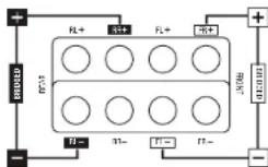
INTERNAL BRIDGING
Terminals that can be used in bridging mode are identified by the black and white boxes above each terminal. The two black boxes and the two outlined boxes work together to create an internally bridged hookup.
TOOLS OF THE TRADE
Listed next are the majority of the tools required to perform an installation. Having the proper tools will make the installation that much easier.
- Phillips head screwdriver
- Solderless, crimp-on connectors and a crimping tool
• Electric drill and 3/16" and 1/8" drill bits • Safety glasses
• Permanent ink marker or pencil • DMM or VOM - Safety glasses
- Nylon tie straps
- Wire strippers and cutters
- Wire crimper
• Electrical tape • Grommets for passing wires through metal car walls - Amplifier Power Wire
END PANEL LAYOUTS
PA D4000.4 Line Level Inputs/Controls
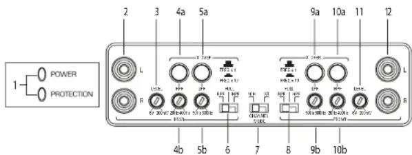
- Status LEDs (on top of amplifier): Power and Protection—Power will illuminate to indicate the amplifier is on and operating normally; protection will illuminate if the amplifier shuts down due to short circuit, DC offset, or overheating detected by onboard protection circuitry.
Rear Controls
- Rear Line Level Inputs—accepts line level input from the rear channels of a head unit.
- Rear Level Control—Adjusts the gain of the rear channels to match the output voltage from your head unit.
- (a) Rear High-Pass Frequency Button—When FREQ x 10 is engaged, the crossover's range increases to 200Hz - 4kHz.
(b) Rear HPF Control—Adjusts the high pass filter frequency to attenuate frequencies below the setting on the control. - (a) Rear Low-Pass Frequency Button—When FREQ x 10 is engaged, the crossover's range increases to 500Hz - 5kHz.
(b) Rear LPF Control—Adjusts the low pass filter frequency to attenuate frequencies above the setting on the control. - Rear BPF, FULL, HPF Switch—Selects full range, high pass filter, or band-pass filter. The BPF setting allows you to use both the high pass filter and low pass filter, and it is for use with mid-range drivers. The FULL setting does not attenuate any frequencies and is for full range speaker systems. The HPF setting attenuates low frequencies and is used with mid-range speakers and tweeters.
- Channel Mode Switch (ST/4Ch)—Set the switch to 4CH if you are using four channel outputs from your head unit to the FL, FR, RL, RR inputs on the amplifier. Set the switch to ST (stereo) mode if you are using two channel outputs from your head unit. In the ST position, the amplifier will take the signal input to the FL and RR inputs and send the same signal's also to the RL and RR amplifier channels.
-
Front BPF, FULL, HPF Switch—Selects full range, high pass filter, or band-pass filter. The BPF setting allows you to use both the high pass filter and low pass filter, and it is for use with mid-range drivers. The FULL setting does not attenuate any frequencies and is for full range speaker systems. The HPF setting attenuates low frequencies and is used with mid-range speakers and tweeters.
-
(a) Front Low-Pass Frequency Button—When FREQ x 10 is engaged, the crossover's range increases to 500Hz - 5kHz.
(b) Front LPF Control—Adjusts the low pass filter frequency to attenuate frequencies above the setting on the control.
10 (a) Front High-Pass Frequency Button—When FREQ x 10 is engaged, the crossover's range increases to 200Hz - 4kHz.
(b) Front HPF Control—Adjusts the high pass filter frequency to attenuate frequencies below the setting on the control. - Front Level Control—Adjusts the gain of the front channels to match the output voltage from your head unit.
- Front Line Level Inputs—Accepts line level input from the front channels of a head unit.
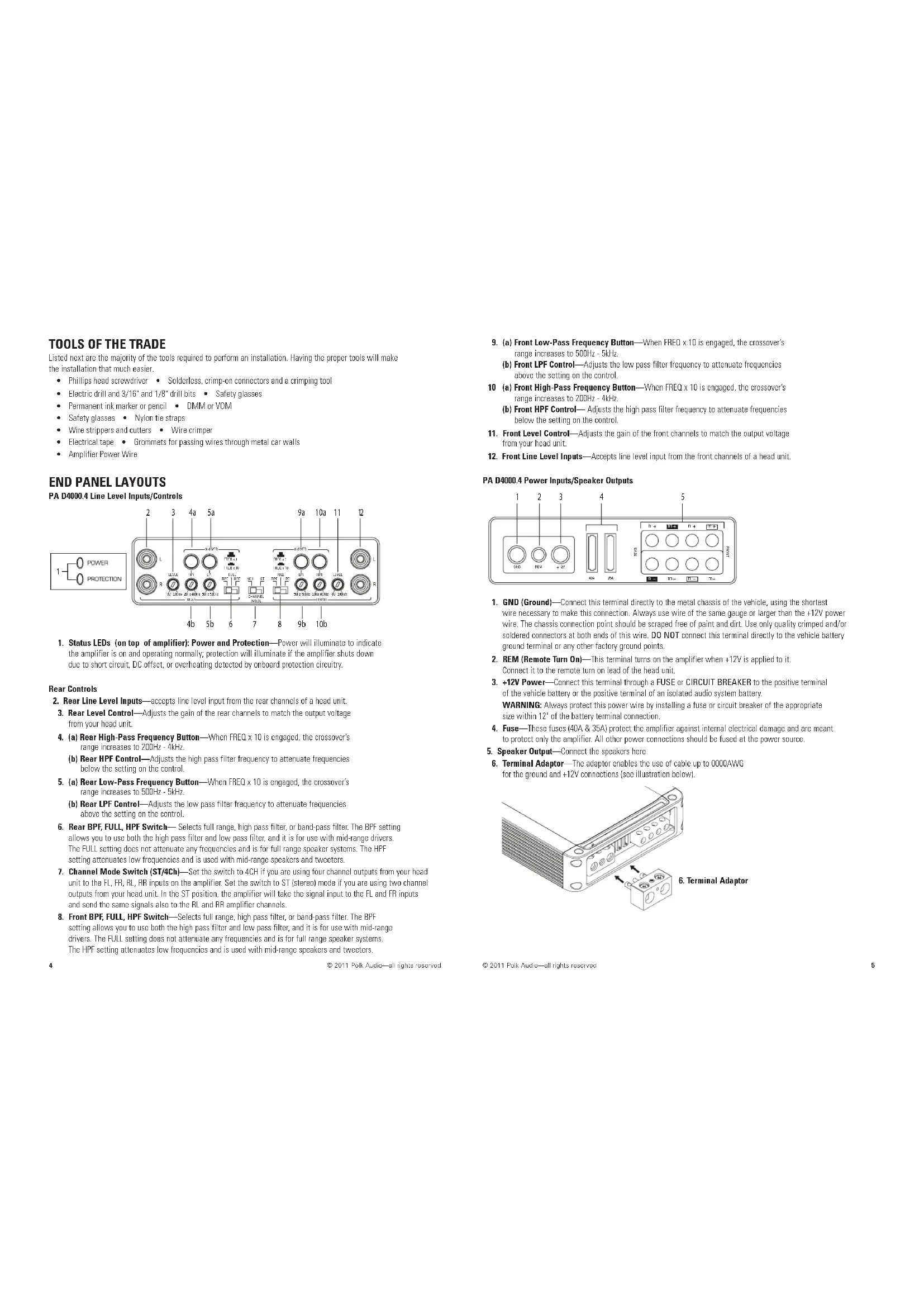
PA D4000.4 Power Inputs/Speaker Outputs
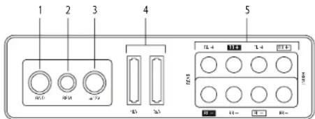
- GND (Ground)—Connect this terminal directly to the metal chassis of the vehicle, using the shortest wire necessary to make this connection. Always use wire of the same gauge or larger than the +12V power wire. The chassis connection point should be scraped free of paint and dirt. Use only quality crimped and/or soldered connectors at both ends of this wire. DO NOT connect this terminal directly to the vehicle battery ground terminal or any other factory ground points.
- REM (Remote Turn On)—This terminal turns on the amplifier when +12V is applied to it. Connect it to the remote turn on lead of the head unit.
- +12V Power—Connect this terminal through a FUSE or CIRCUIT BREAKER to the positive terminal of the vehicle battery or the positive terminal of an isolated audio system battery. WARNING: Always protect this power wire by installing a fuse or circuit breaker of the appropriate size within 12" of the battery terminal connection.
-
Fuse—These fuses (40A & 35A) protect the amplifier against internal electrical damage and are meant to protect only the amplifier. All other power connections should be fused at the power source.
-
Speaker Output—Connect the speakers here
-
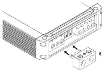
Terminal Adaptor—The adaptor enables the use of cable up to 0000AWG for the ground and +12V connections (see illustration below).
natural_image
Technical line drawing of a mechanical component with mounting holes and a separate housing (no text or symbols)- Terminal Adaptor
AMPLIFIER WIRING
Power Connections
• PA D4000.4 Fuse Size: 2 x 40 AMP ATC
• Power connections accept up to 4 AWG wire.
• 4 AWG power and ground wire recommended for optimal performance.
- Connect +12V to the battery through fuse holder. This connection provides
+12V main power to the amplifier.
• Power wire must be fused within 12" of the battery.
- Ground the amplifier using a good chassis ground as close as possible to the amplifier.
- Connect REM terminal to remote turn-on lead from the head unit. This connection provides +12V power to turn-on the amplifier.
- Add extra ground wire between the negative terminal of the battery and the chassis.
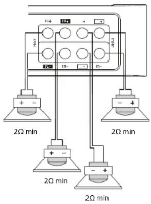
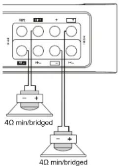
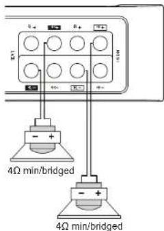
Speaker Wiring Diagram PA D4000.4
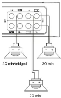
Bridging
The amplifier is capable of bridging two full range channels into a single full range channel with higher output power. For instance, one Front and one Rear channel when wired as shown will increase the output power from 125W per channel to 400W per channel (for a 4 Ohm load). The most common are shown in the figure: four full range channels, two full range channels and a bridged sub, or two bridged subwoofers.
Internal Bridging
Terminals that can be used in bridging mode are identified by the black and outlined boxes next to each terminal. The two black boxes and the two outlined boxes work together to create an internally bridged hookup.
AMPLIFIER INSTALLATION
Mounting Locations
The location of your amplifier will depend on several important issues. Due to the low profile and compact size of the Polk Audio PA D Series amplifier, there are many possible installation locations that will yield satisfactory amplifier performance. Always mount the amplifier in a place that protects the amplifier from the elements. In addition, mount the amplifier on a stable, flat surface.
NOTE: Mounting amplifiers upside down is not recommended and may cause premature thermal shutdown.
WARNING! DO NOT MOUNT any amplifier in the engine compartment. Amplifiers are not designed to endure the harsh environment of an engine compartment.
Passenger Compartment
If you are going to mount the amplifier in the passenger compartment, make sure you have adequate room for ventilation. When mounting your amplifier under a seat or similar area, keep a minimum of 1" of clearance around the amplifier for adequate cooling.
Trunk Compartment
Mounting your amplifier in the trunk provides excellent performance as long as you do not restrict the airflow around the heatsink of the amplifier. For optimal results, mount the amplifier with as much clearance as possible. This type of mounting will yield the best cooling due to the convection effect of the amplifier chassis.
INSTALLATION GUIDELINES
Power for systems with a single amplifier can be supplied by most automotive electrical systems. Systems with multiple amplifiers may require a higher capacity battery, altamator or the use of a storage capacitor. Polk Audio PA D Series amplifiers do generate a certain amount of heat as part of normal operation. Be sure the area around the amplifier is unobstructed to allow adequate air circulation. Remember, beach blankets, last week's laundry, school books and homework papers placed on top of the amplifier impede air flow and may cause damage.
- Please read this owner's manual carefully before installing your amplifier.
- Disconnect the battery ground terminal prior to making any electrical connections.
- Check for any hazards or obstructions such as gas tanks, fuel or brake lines, and wiring harnesses before mounting the amplifier.
- Pick a mounting location that will provide adequate access and ventilation and protect the amplifier from heat, moisture, and dirt.
- Avoid sharp metal areas when routing cables to the amplifier, and run RCA cables away from the power cables and other potentially noisy car harnesses.
- The amplifier should be grounded with a short, heavy gauge wire connected directly to the car at a bare metal surface, preferably scraped body metal. Do not use factory ground locations, seat bolts, or brackets that are spot welded.
- Always fuse your power connection within 12 inches of the battery terminal. Use a fuse or circuit breaker rated slightly more than the on-board fuse(s) of the amplifiers). The gauge of power wire used should take into account the total current draw of the system, and the length of wire used. IASCA and other auto sound competition organizations have charts available for this; you can also find a chart in the MECP study guide. Minimum wire gauge recommendations for the individual amplifiers are listed on the specification page. Always use the same gauge wire for the amplifier ground that you use for the power wire. Be sure to examine the battery ground cable of the vehicle, and if necessary, upgrade it by adding an additional ground wire that is the same gauge as the amplifier's power wire. Remember, the amplifier can only deliver its rated output when it is not current limited by the power and ground supply wires.
-
This amplifier is designed to drive a speaker load that measures from 2 to 8 Ohms for full range channels and 4 Ohm minimum for bridged channels. Keep in mind that heat is the long-term enemy of automotive electronics and the lower your speaker load, the more heat is generated. For low-impedance speaker applications or restricted ventilation installations, an external cooling fan may be advisable.
-
Battery and ground connections to the vehicle should be made with crimped ring terminals of the appropriate size (surface area is what counts;) soldering the terminals after crimping is also recommended.
-
Due to the high-frequency MOSFET switching power supply, filtering the power cable is not generally required (remember that the amp can't deliver full output if the power supply is restricted.) Proper grounding of the signal source is mandatory for the amplifier to reach its performance peak. If the RCA inputs are not grounded adequately via the signal source, electrical noise from the vehicle may be picked up in the system.
Step By Step Installation
-
Determine the location for the amplifier. Refer to the Mounting Locations section of this guide.
-
Decide on the system configuration for your amplifier. For system suggestions, refer to the Speaker Wiring Diagrams section of this guide.
-
Run all the wires from the amplifier location to the speakers, source unit, and battery. Do not connect the battery at this time. Be sure to run Line levels and power and speaker wires away from factory electrical wires and system as they pose a great potential for induced system noise.
-
Pre-drill amplifier mounting holes. Be sure to "think before you drill." Gas tanks, fuel lines, and other obstructions have a nasty way of hiding themselves. For best results use a marking pen to mark the mounting holes and pre-drill these holes with a standard 1/8" drill bit.
-
Mount the amplifier. Make sure the amplifier is mounted on a flat surface. If this is not possible, do not over tighten the screws so that the chassis of the amplifier is twisted or bent.
-
Turn the vehicle's key switch to the off position.
-
Disconnect the vehicle's battery ground terminal.
B. Connect power wires to the amplifier (ground first, then +12V and REM).
-
Connect the line level and speaker wires to the amplifier. Check the quality of your speakers and signal connections. This will determine the ultimate performance of your Polk Audio PA D Series amplifier. Refer to the Line Level Inputs/Controls and Speaker Wiring Diagrams sections of this guide for correct wiring instructions.
-
Reconnect the ground terminal to the battery after power, speaker, and line level connections are completed.
-
Set crossovers. Refer to the Line Level Inputs/Controls section of this manual for detailed instructions.
-
Once satisfied that all connections and settings are correct, install the fuse located near the vehicle's battery and proceed to the Testing the System section of this manual.
WARNING! NEVER exceed the recommended fuse size of this amplifier. Failure to do so will result in the voiding of your warranty and possible damage to the amplifier.
SET UP AND TROUBLESHOOTING
Testing the System
After you have completed the installation, you need to test the system. This will help ensure years of trouble-free operation. Please refer to the listed steps below when testing the sound of your Polk Audio PA D Series amplifier.
- Check all the wiring connections to be sure they are correct and secure.
- Turn the signal source volume control all the way down. Set any tone controls to their flat or defeated positions. This includes the loudness control.
- Turn the level controls of the amplifier to their minimum positions.
- Turn the head unit on. Check to see if the power LED located on the connection side of the amplifier is on. If not, please refer to the Power Inputs/Speaker Outputs and the Troubleshooting Tips sections of this manual for instructions.
- If using an aftermarket head unit, turn the level controls of the amplifier about one quarter of a turn counterclockwise. Slowly increase the volume level of the head unit so that you can hear the output of the system. If no sound is heard or if the output is distorted, turn the system off immediately. Refer to the Power Inputs/Speaker Outputs and the Troubleshooting Tips sections of this manual to solve your installation problems.
- Check to make sure the output for each channel is correct. If the active crossovers are used, check to make sure that each output is correct from the amplifier. When using active crossovers on midrange
and tweeters, do not use crossover frequencies lower than recommended. If the system is not configured properly, refer to the Line Level Inputs/Controls section of this manual and take corrective action.
- If the output is clear and undistorted, continue to the Adjusting the Sound of the System section of this manual.
Adjusting the Sound of the System
Once you have checked the system's operation, adjust the sound of the system. Adjusting the sound of the system is accomplished by setting the level controls and adjusting the internal crossovers (see Line Level Inputs/Controls on page 4).
- Turn the signal source volume control all the way down. Set any tone controls to their flat or defeated positions. This includes the loudness control.
- Turn the level controls of the amplifier to their minimum positions.
- Choose music with high dynamic content that you like, with which you are familiar, and will be used most often in the system.
- Turn the head unit's volume control up to its highest undistorted output level. If you lack test equipment, this point occurs between 3/4 to full volume depending on the quality of your head unit. Listen for any audible distortion. If any distortion is audible, reduce the volume of the head unit until you have an undistorted output. Leave the volume control at this position during your system tuning.
- While listening to your chosen dynamic music, turn up the level control corresponding to the midrange output until you hear slight distortion and turn the level control back slightly for an undistorted output. Depending on your system, the midrange and tweeter output may be on the same output channels.
- Turn up the level control corresponding to the tweeter output until you hear slight distortion and turn back the level control slightly for an undistorted output. Depending on your system the midrange and tweeter output may be on the same output channels.
- Fine-tune the output level between midrange and tweeters. Refer to the Line Level Inputs/Controls section of this manual for detailed instructions.
- Repeat Steps 5-7 for the rear speakers. If you do not have rear speakers continue to Step 10.
- Set levels between the front and rear midrange and tweeters for optimum front/rear balance.
- Turn up the level control corresponding to the woofer output until you hear slight distortion and turn back the level control slightly for an undistorted output.
- Fine-tune the output level between satellite speakers and the woofers. Refer to the Line Level Inputs/Controls section of this manual for controls. Adjust the level to the bass output of the woofer to match the sonic requirements of the system.
- Enjoy your awesome Polk Audio PA D Series amplifier.
TROUBLESHOOTING TIPS
| Symptom Probable Cause | Action To Take |
| No output | |
| Low or no remote turn-on. | Check remote turn-on at amplifier and repair as needed. |
| Fuse blown. | Check power wire's integrity and check for speaker shorts. Fix as needed and replace fuse. |
| Power wires not connected. | Check power wire and ground connections and repair or replace as needed. |
| Audio input not connected. | Check line level connections and repair or replace as needed. |
| Speaker wires not connected. | Check speaker wires and repair or replace as needed. |
| Speakers are blown. | Check system with known working speaker and repair or replace speakers as needed. |
TROUBLESHOOTING TIPS
| Symptom Probable Cause | Action To Take |
| Audio cycles on and off | |
| Thermal protection engages when amplifier heat sink temperature exceeds 85^ C ( 185^ F). | Make sure there is proper ventilation for amplifier and improve ventilation as needed. |
| Loose or poor audio input. Check line level | connections and repair or replace as needed. |
| Loose power connections. Check power wires and ground connections and repair or replace as needed. | |
| Distorted output | |
| Amplifier level sensitivity set too high exceeding maximum capability of amplifier. | Readjust gain. Refer to the Adjusting the Sound of the System section of this manual. |
| Impedance load to amplifier too low. Check speaker impedance load if below (2 Ohms, 4 Ohms min bridged); rewire speakers to create higher impedance. | |
| Shorted speaker wires. Check speaker wires and repair or replace as needed. | |
| Speaker not connected to amplifier properly. | Check speaker wires and repair or replace as needed. |
| Internal crossover not set properly for speakers. | Readjust crossovers. Refer to the Line Level Inputs/Controls section of this manual. |
| Speakers are blown. Check system with known working speakers and fix or replace as needed. | |
| Poor bass response | |
| Speakers wired with wrong polarity causing cancellation at low frequencies. | Check speaker polarity and fix as needed. |
| Crossover set incorrectly. Reset crossovers. Refer to the Amplifier Settings section. | |
| Impedance load at amplifier is too low. Check speaker impedance load if below (2 Ohms, 4 Ohms min bridged); rewire speakers to create higher impedance. | |
| Battery fuse blowing | |
| Short in power wire or incorrect wiring. Check power wires and ground connections and repair or replace as needed. | |
| Fuse used is smaller than recommended. Replace with proper fuse size. | |
| Actual current exceeds fuse rating. Check speaker impedance load if below (2 Ohms, 4 Ohms min bridged); rewire speakers to create higher impedance. | |
| Amplifier fuse blowing | |
| Fuse used is smaller than recommended. Replace with proper fuse size. | |
| Impedance load at amplifier is too low. Check speaker impedance load if below (2 Ohms, 4 Ohms min bridged); rewire speakers to create higher impedance. | |
| Speaker is blown with shorted outputs. Check system with known working speakers and fix or replace as needed. | |
| Actual current exceeds fuse rating. Check speaker impedance load if below (2 Ohms, 4 Ohms min bridged); rewire speakers to create higher impedance. | |
SPECIFICATIONS
| Amplifier | PA D4000.4 |
| Type | BridgeableClass D MOSFET |
| Channels | 4 channel |
| RMS Continuous Power @ 4 Ohms | 125 W x 4 |
| RMS Continuous Power @ 2 Ohms | 200 W x 4 |
| Power Bridged @ 4 Ohms | 400 W x 2 |
| Distortion at Rated Power | <0.1% |
| Minimum Impedance Bridged 4 Ohms | |
| Minimum Impedance Not Bridged | 2 Ohms |
| Signal-to-noise Ratio | 105dB |
| Frequency Response | 20Hz-20kHz |
| Damping Factor | >100 |
| Crossover Filter Slope (dB/octave) | 12 dB/octave |
| Filter Switch (Front) | 3-position(IHPF, Full, BPF) |
| High Pass Filter Frequency Range (Front) | 20Hz - 4kHz |
| Low Pass Filter Frequency Range (Front) | 50Hz - 5kHz |
| Front Gain Control | 200mV - 6V |
| Amplifier | PA D4000.4 |
| Filter Switch (Rear) | 3-position(HPF, Full, BPF) |
| High Pass FilterFrequency Range (Rear) | 20Hz - 4kHz |
| Low Pass FilterFrequency Range (Rear) | 50Hz - 5kHz |
| Roar Gain Control | 200mV - 6V |
| Line Level Inputs (y/nl) | Yes |
| Line Level Outputs (y/nl) | No |
| LED Power Indicator | Yes |
| LED Protection Indicator | Yes |
| Supply Voltage | 10V - 16V |
| Fusing & Power/Type | {1} 40A {1} 35A ATC |
| Power Connections | 4 AWG |
| Ground Connections | 4 AWG |
| Speaker Connections | 12 AWG |
| Height | 1 13/16" (46 mm) |
| Depth | 6 3/4" (171.5 mm) |
| Width | 10 15/16" (277.8 mm) |
| Width w/ Terminal Adaptor | 11 11/16" (299.9 mm) |
| Weight | 5 lbs (2.7 kg) |
TABLE DES MATIÈRES
INTRODUCTION....13
CONTENU DE LA BOÎTE 13
ÉCOUTEZ BIEN 13
PONTAGE INTERNE 13
OUTILS REQUIS....14
CONFIGURATION DES PANNEAUX....14 - 15
OUTILS REQUIS
natural_image
Technical line drawing of a mechanical component with mounting holes and a separate inset showing a pin detail (no text or symbols)© 2011 Polk Audio—al rights reserved
CÂBLAGE DE L'AMPLIFICATEUR
Alimentation
natural_image
Technical diagram of a mechanical assembly with bolt holes and a separate housing (no text or symbols)- Terminal-Adapter
VERSTÄRKERANSCHLUSS
Stromanschlüsse
4Ω min/bridged
VERSTÄRKERINSTALLATION
Einbaupositionen
natural_image
Technical line drawing of a mechanical component with mounting holes and a separate inset showing internal structure (no text or symbols)© 2011 Polk Audio-al rights reserved
2Ω min
Ligação em ponte
Polk Audio, Inc., warrants to the original retail purchaser only. This warranty will terminate automatically prior to its stated expiration if the original retail purchaser sets or transfers the Product to any other party. Polk Audio, Inc., warrants, to the original retail purchaser only, that the this Polk Audio Amplifier Product will be free from defects in material and workmanship for a period of one (1) year from the date of original retail purchase from a Polk Audio Authorized Dealer, and 2 years if installed by the same dealer.
To allow Polk Audio to offer the best possible warranty service, please register your new product online at www.polkaudio.com/registration or call Polk customer service 800-377-7655 in the USA and Canada (provide the USA: 410-258-3600) within ten (10) days of the date of original purchase. Be sure to keep your original purchase receipt. Defective Products must be shipped, together with proof of purchase, prepaid insured to the Polk Audio Authorized Dealer from whom you purchased the Product, or to the Factory at 1 West Way, Visa, California 92081. Products must be shipped in the original shipping container or its cocktail; in any case the risk of loss or damage in transit is to be borne by you. If upon examination at the Factory or Polk Audio Authorized Dealer it is determined that the unit was defective in materials or workmanship at any time during this Warranty period. Polk Audio or the Polk Audio Authorized Dealer will, at its option, repair or replace this Product at no additional charge, except as sat forth below. All replaced parts and Products become the property of Polk Audio. Products replaced or repaired under this warranty will be returned to you, within a reasonable time, freight preparation.
This warranty does not include service or parts to repair damage caused by accident, disaster, misuse, nausea, negligence, inadequate packing or shipping procedures, commercial use, votoops inputs in excess of the rated maximum of the unit, cosmetic appearance of cabinetry not directly attributable to defect in materials or workmanship, or service, repair, or modification of the Product which has not been authorized or approved by Polk Audio. This warranty shall terminate if the Serial number on the Product has been removed, tampered with or defaced. This warranty is in lieu of all other expressed Warranties. If this Product is defective in materials or workmanship as warranted above, your solo remote shall be repair or replacement as provided above. In no event will Polk Audio, Inc. be liable to you for any incidental or consequential damages arising out of the use or inability to use the Product, even if Polk Audio, Inc. or a Polk Audio Authorized Dealer has been advised of the possibility of such damages, or for any claim by any other party. Some states do not allow the exclusion of limitation to consequential damages, so the above limitation and exclusion may not apply to you. All implied warranties on this product are limited to the duration of this expressed Warranty. Some states do not allow limitation on how long an implies Warranty lasts, so the above limitations may not apply to you. This Warranty gives you specific legal rights, and you also may have other rights which vary from state to state.
This Warranty applies only to Products purchased in Canada, the United States of America, its possessions, and U.S. and NATO armed forces exchanges and audio clubs. The Warranty terms and conditions applicable to Products purchased in other countries are available from the Polk Audio Authorized Distributors in such countries.