PDUMV20HV36 - Power strip Tripp Lite - Free user manual and instructions
Find the device manual for free PDUMV20HV36 Tripp Lite in PDF.
User questions about PDUMV20HV36 Tripp Lite
0 question about this device. Answer the ones you know or ask your own.
Ask a new question about this device
Download the instructions for your Power strip in PDF format for free! Find your manual PDUMV20HV36 - Tripp Lite and take your electronic device back in hand. On this page are published all the documents necessary for the use of your device. PDUMV20HV36 by Tripp Lite.
USER MANUAL PDUMV20HV36 Tripp Lite
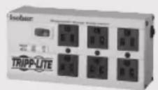
Basic, Metered and Metered with Isobar® Surge Protection Vertical Rack PDUs
Models:
PDUMV30, PDUMV30HV, PDUV30HV, PDUV30-36, PDUMV30-ISO, PDUMV20HV, PDUMV20HVL6, PDUMV20HV-36, PDUV20HVL6-72
(Series Numbers: AGIB6672, AGPD6673, AGPD6674)
Important Safety Instructions 2 ImportantWarnings 2
Installation 4
Features 4
Warranty & Product Registration 6
Espanol 7
Français 13
Pycckn 19
Deutsch 25
WARRANTY REGISTRATION
Register your product today and be automatically entered to win an ISOBAR® surge protector in our monthly drawing!

triplite.com/warranty

TrippLite.Eaton.com/support
Copyright © 2023 Tripp Lite. All rights reserved.
Important Safety Instructions
SAVE THESE INSTRUCTIONS
This manual contains instructions and warnings that should be followed during the installation, operation and storage of this product. Failure to heed these instructions and warnings will void the product warranty.

CAUTION Only those who are properly trained or qualified to use this device should do so. Anyone who is not trained or qualified should not use this device unless it is under the supervision of someone who is properly trained or qualified to do so. Children must be supervised to ensure that they do not use the device as a toy.
Do not install this device if there is not at least 10 meters (30 feet) or more of wire between the electrical outlet and the electrical service panel.
Never use the device if the cord and plug are damaged; if it is not working properly, or if it has been dropped or damaged, take it to an authorized service center for inspection and repair.
If the power cord is damaged, it must be replaced by the manufacturer, its authorized service agent, or by qualified personnel in order to avoid a danger.
ImportantWarnings
- The PDUMV30-ISO PDU model provides surge and line noise protection to connected equipment through its outlets.
- Non-ISO PDUs do not provide surge and line protection to connected equipment.
- The PDU is designed for indoor use only in a controlled environment away from excess moisture, temperature extremes, conductive contaminants, dust or direct sunlight.
- The PDU must be installed by a qualified technician only.
- Install in accordance with National Electrical Code standards. Be sure to use the proper overcurrent protection for the installation, in accordance with the plug/equipment rating.
- Connect the PDU to an outlet that is in accordance with your local building codes and adequately protected against excess currents, short circuits, and earth faults.
- Keep indoor ambient temperatures between 32^ and 77^ (0^ and 25^)
- Use of this equipment in life support applications where failure of this equipment can reasonably be expected to cause the failure of the life support equipment or to significantly affect its safety or effectiveness is not recommended. Do not use this equipment in the presence of a flammable anesthetic mixture with air, oxygen or nitrous oxide.
- Do not connect the PDU to an ungrounded outlet or extension cords or adapters that eliminate the connection to ground.
- The power requirement for each piece of equipment connected to the PDU must not exceed the individual outlet's load rating.
- The plug on the power supply cord serves as the disconnect device.
ImportantWarnings
- The electrical outlets that supply power to the equipment should be near the equipment and easily accessible.
- The total power requirement for equipment connected to the PDU must not exceed the maximum load rating for the PDU.
- Do not drill into or attempt to open any part of the PDU housing. There are no user-serviceable parts inside.
- Do not attempt to modify the PDU, including the input plugs and power cables.
- Do not attempt to use the PDU if any part of it becomes damaged.
- Do not attempt to mount the PDU to an insecure or unstable surface.
- Never attempt to install electrical equipment during a thunderstorm.
- Install in accordance with National Electrical Codes. Be sure to use the proper overcurrent protection for the installation, in accordance with the plug rating/equipment rating as follows:
| Model Series Number Overcurrent Protection | ||
| PDUV30HV AGIB6672 30A | ||
| PDUV20HVL6-72 AGIB6672 20A | ||
| PDUMV30, PDUMV30-ISO AGPD6673 | 30A | |
| PDUMV16HV, PDUMV20HV, PDUMV20HVL6, PDUMV20HV-36 | AGPD6674 20A | |
| PDUMV30HV AGPD6675 30A | ||
Installation
Note: Regardless of configuration, the user must determine the fitness of hardware and procedures before mounting. The PDU and included hardware are designed for common rack and rack enclosure types and may not be appropriate for all applications.
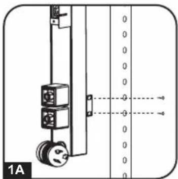
1A Zero U Rack Configuration (Mounting Brackets).
Prior to installation, determine the rack location in which the PDU is to be installed. Attach the mounting brackets to the back of the PDU as shown, using the included screws. To assist with proper positioning, the brackets have four screw holes each; make sure that the same two holes are used to attach each bracket to the PDU. After attaching the brackets, position the PDU in the rack and mount it by installing four user-supplied fasteners through the brackets into the rack.
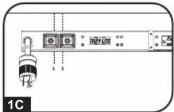
13 Zero U Rack Configuration (Mounting Buttons).
Attach the included mounting buttons to the PDU. Position the PDU as desired in the rack enclosure, align the buttons with the rack mounting slots, and slide the PDU into position.
1C Under-Counter Configuration. The PDU may be
installed under a counter using the included mounting brackets. Attach the mounting brackets to the back of the PDU as shown in STEP 1A. Secure the PDU to the underside of the counter by installing two user-supplied screws through each bracket into the counter.
Note: Your model may differ.
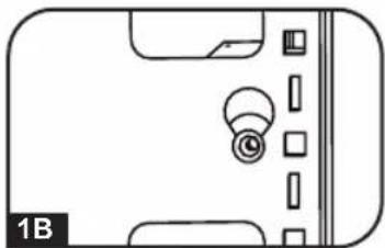
Features
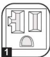

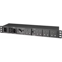
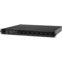
1 NEMA 5-15/20R Outlet (PDUMV30, PDUMV30-ISO, PDUV30-36)
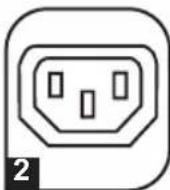
C13 Outlet (PDUMV20HV, PDUV20HVL6-72, PDUMV20HVL6, PDUMV20HV-36, PDUMV30HV, PDUV30HV)
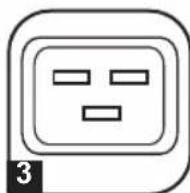
C19 Outlet (PDUMV20HV, PDUV20HVL6-72, PDUMV20HVL6, PDUMV20HV-36, PDUMV30HV, PDUV30HV)
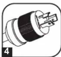
4 L5-30P, L6-20P or L6-30P Locking Plug
Features
5 Circuit Breaker: If the current drawn by the equipment connected to the PDU exceeds the Maximum Load Rating, the circuit breaker will trip to prevent possible damage. When the circuit breaker trips,

PROTECTION

PRESENTFAULT

LINE

OK
its plunger will pop up. Disconnect excess equipment and allow the breaker to cool at least one minute before depressing the plunger to reset the breaker.
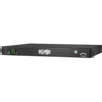
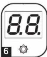
6 Ammeter: The total electrical current used by the PDU will be displayed on the digital meter in amperes (select models only).
7 Diagnostic Indicator Lights: The three
LEDs on the front panel show current power conditions (from left to right):
Protection Present (Green LED): Indicates the surge-suppression components are intact and providing full protection against spikes and surges. This LED should be lit anytime the PDU is plugged in and power is present. If the Protection Present LED does not light, then some of the surge suppression components are not functioning and the unit should be returned for repair as soon as possible. You may still use the unit; however, connected equipment will be protected from spikes and surges at a lesser level than normal.
Line Fault (Red LED)*: Indicates a wiring fault has been detected. If this LED illuminates at any time while the unit is plugged in, the fault should be repaired by a qualified electrician as soon as possible. This LED indicates that phases are reversed, ground is missing or some other sort of wiring error exists in the circuit the PDU is plugged into. The Line Fault detector circuitry will identify most common wiring faults, but will not necessarily detect every possible type of fault.
Line "OK" (Green LED): Indicates that nominal AC power is present with no wiring faults detected. When this LED is illuminated, AC power is safe for connected equipment.
- If the Line Fault (Red LED) indicator illuminates, carefully check the AC receptacle the PDU is plugged into. The receptacle must be tight and securely grounded. A loose AC receptacle may cause the Line Fault LED to illuminate. The Red LED indicates the presence of a wiring fault, but does not indicate the exact nature of the fault. Only qualified electricians should make necessary outlet repairs.
If the Line Fault indicator illuminates and power is not present at the outlets, the PDU's surge-suppression components have been compromised as a result of surge damage. For service, call Tripp Lite Customer Support at 773.869.1234 to remedy the problem or receive instructions about return, repair or exchange.
Warranty & Product Registration
LIMITED WARRANTY
Seller warrants this product, if used in accordance with all applicable instructions, to be free from original defects in material and workmanship for a period of 5 years (except internal UPS system batteries outside USA and Canada, 1 year) from the date of initial purchase. If the product should prove defective in material or workmanship within that period, Seller will repair or replace the product, in its sole discretion. Service under this Warranty can only be obtained by your delivering or shipping the product (with all shipping or delivery charges prepaid) to: Tripp Lite, 1111 W. 35th Street, Chicago, IL 60609 USA. Seller will pay return shipping charges. Visit tripplite.com/support before sending any equipment back for repair.
THIS WARRANTY DOES NOT APPLY TO NORMAL WEAR OR TO DAMAGE RESULTING FROM ACCIDENT, MISUSE, ABUSE OR NEGLECT. SELLER MAKES NO EXPRESS WARRANTY OTHER THAN THE WARRANTY EXPRESSLY SET FORTH HEREIN. EXCEPT TO THE EXTENT PROHIBITED BY APPLICABLE LAW, ALL IMPLIED WARRANTYES, INCLUDING ALL WARRANTYES OF MERCHANTABILITY OR FITNESS, ARE LIMITED IN DURATION TO THE WARRANTY PERIOD SET FORTH ABOVE; THIS WARRANTY EXPRESSLY EXCUSES ALL INCIDENTAL AND CONSEQUENTIAL DAMAGES. (Some states do not allow limitations on how long an implied warranty lasts, and some states do not allow the exclusion or limitation of incidental or consequential damages, so the above limitations or exclusions may not apply to you. This Warranty gives you specific legal rights, and you may have other rights which vary from jurisdiction to jurisdiction).
WARNING: The individual user should take care to determine prior to use whether this device is suitable, adequate or safe for the use intended. Since individual applications are subject to great variation, the manufacturer makes no representation or warranty as to the suitability or fitness of these devices for any specific application.
PRODUCT REGISTRATION
Visit tripplite.com/warranty today to register your new Tripp Lite product. You'll be automatically entered into a drawing for a chance to win a FREE Tripp Lite product!*
- No purchase necessary. Void where prohibited. Some restrictions apply. See website for details.
Regulatory Compliance Identification Numbers
For the purpose of regulatory compliance certifications and identification, your Tripp Lite product has been assigned a unique series number. The series number can be found on the product nameplate label, along with all required approval markings and information. When requesting compliance information for this product, always refer to the series number. The series number should not be confused with the marking name or model number of the product.
Tripp Lite has a policy of continuous improvement. Specifications are subject to change without notice. Photos and illustrations may differ slightly from actual products.

TrippLite.Eaton.com/support
PykoBODCTBO NOJIb3OBaTeJIA
BepTnkaJIbHbIe cToeUHbIe PDU: 6a3ObIe; c N3MepNTeJIeM; c N3MepNTeJIeM n CeTeBbIM φnJIbTpom Isobar®
Modell:
PDUMV30, PDUMV30HV, PDUV30HV, PDUV30-36, PDUMV30-ISO, PDUMV20HV, PDUMV20HVL6, PDUMV20HV-36, PDUV20HVL6-72
(Homep cepin: AGIB6672, AGPD6673, AGPD6674)
Baxhblye yka3aHnno TeXnke 20
6e3OnacHocTn
BaxHbIe npedynpeXdEHHa 20
YctaHOBka 22