
PDUMH15HVNET - Power strip Tripp Lite - Free user manual and instructions
Find the device manual for free PDUMH15HVNET Tripp Lite in PDF.

| Product Type | Switched PDU for rack mounting |
| Brand | Tripp Lite |
| Model | PDUMH15HVNET |
| Input Voltage | 208/230 V AC, 50/60 Hz |
| Input Current Rating | 15 A maximum |
| Input Type | IEC 60320 C14 (detachable cord with C13 connector) |
| Output Receptacles | IEC 60320 C13 (quantity varies by model, typically 8 to 12) |
| Digital Display | Ammeter indicating total load in amps |
| Network Management | Via integrated WEBCARDLX card (SNMP, Web, SSH, Telnet) |
| Mounting | 1U horizontal, vertical (0U), wall, under-counter, reduced depth |
| Enclosure Material | Steel |
| Operating Temperature | 0 °C to 50 °C |
| Warranty | 2 years |
| Weight | Approximately 2-3 kg (not supplied, estimate) |
| Usage | Indoor only, controlled environment |
| Installation | By qualified technician only |
| Overload Protection | Requires upstream 15 A maximum circuit breaker |
| Main Functions | AC power distribution, remote outlet switching via network, load display |
| Maintenance | No user-serviceable parts. Clean with a dry cloth. |
| Spare Parts | Contact Tripp Lite technical support (techsupport@tripplite.com) |
| Repairability | Not user-repairable. Return to manufacturer for repair. |
Frequently Asked Questions - PDUMH15HVNET Tripp Lite
User questions about PDUMH15HVNET Tripp Lite
0 question about this device. Answer the ones you know or ask your own.
Ask a new question about this device
Download the instructions for your Power strip in PDF format for free! Find your manual PDUMH15HVNET - Tripp Lite and take your electronic device back in hand. On this page are published all the documents necessary for the use of your device. PDUMH15HVNET by Tripp Lite.
USER MANUAL PDUMH15HVNET Tripp Lite
• 208/230V, 50/60 Hz AC Input and Output
Important Safety Instructions 2
Installation 3
Features 6
Technical Support 8
Warranty and Product Registration 8
Español 9
Français 17
Русский 25
Deutsch 33
PROTECT YOUR INVESTMENT!
Register your product for quicker service and ultimate peace of mind.
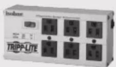
You could also win an ISOBAR6ULTRA surge protector— a \$100 value!
www.tripplite.com/warranty


TrippLite.Eaton.com/support
Copyright © 2023 Tripp Lite. All rights reserved.
Important Safety Instructions
SAVE THESE INSTRUCTIONS
This manual contains instructions and warnings that should be followed during the installation, operation, and storage of this product. Failure to heed these instructions and warnings may affect the product warranty.

CAUTION Only those who are properly trained or qualified to use this device should do so. Anyone who is not trained or qualified should not use this device unless it is under the supervision of someone who is properly trained or qualified to do so.
Children must be supervised to ensure that they do not use the device as a toy.
Never use the device if the cord and plug are damaged; if it is not working properly, or if it has been dropped or damaged, take it to an authorized service center for inspection and repair.
If the power cord is damaged, it must be replaced by the manufacturer, its authorized service agent, or by qualified personnel in order to avoid a danger.
- The PDU provides the convenience of multiple outlets, but DOES NOT provide surge or line noise protection for connected equipment.
- The PDU is designed for indoor use only, in a controlled environment, away from excess moisture, temperature extremes, conductive contaminants, dust or direct sunlight.
- Keep indoor ambient temperature between 32^ and 122^ (0°C and 50°C).
- The PDU must be installed by a qualified technician only.
- Do not attempt to mount the PDU to an insecure or unstable surface.
• Install in accordance with National Electrical Code standards. Be sure to use the proper overcurrent protection for the installation, in accordance with the plug/equipment rating. - Connect the PDU to an outlet that is in accordance with your local building codes and that is adequately protected against excess currents, short circuits and earth faults.
- The electrical outlets supplying power to the equipment should be installed near the equipment and easily accessible.
- Do not connect the PDU to an ungrounded outlet or to extension cords or adapters that eliminate the connection to ground.
- Be sure to provide a local disconnect device on any models that are permanently installed without a plug that is easily accessible.
- Never attempt to install electrical equipment during a thunderstorm.
- Individual equipment connected to the PDU should not draw more current than the individual PDU's outlet's rating.
- The total load connected to the PDU must not exceed the maximum load rating for the PDU.
- Do not attempt to modify the PDU, input plugs or power cables.
- Do not drill into or attempt to open any part of the PDU housing. There are no user-serviceable parts inside.
- Do not attempt to use the PDU if any part of it becomes damaged.
- Use of this equipment in life support applications where failure of this equipment can reasonably be expected to cause the failure of the life support equipment or to significantly affect its safety or effectiveness is not recommended.
Installation
Mounting the PDU
The PDU supports five primary mounting configurations: 1U Rack, 0U Rack (Vertical), Wall, Under-Counter and Reduced-Depth.
Note: Regardless of configuration, the user must determine the fitness of hardware and procedures before mounting. The PDU and included hardware are designed for common rack and rack enclosure types and may not be appropriate for all applications. Exact mounting configurations may vary. Screws for attaching the mounting brackets to the PDU are included. Use only the screws supplied by the manufacturer, or their exact equivalent (#6-32, 3/16" flat head).

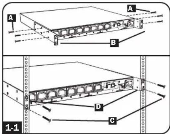
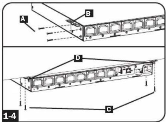
1U Rack Mounting: Use 3 screws A to attach each of the 2 longer mounting brackets B to the PDU as shown. You can mount the PDU in a recessed position by attaching the mounting brackets so they extend beyond the front panel of the PDU. Mount the PDU in the rack by inserting 4 user-supplied screws C through the mounting brackets D and into the mounting holes of the rack rails.

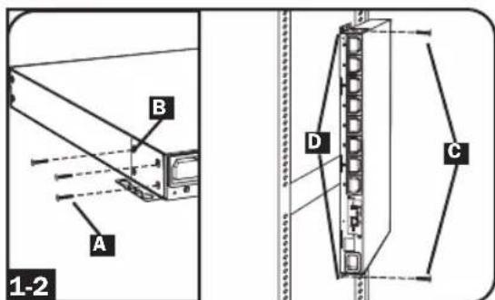
OU Rack Mounting: Use 3 screws A to attach each of the 2 shorter mounting brackets B to the PDU as shown. Mount the PDU vertically by inserting 2 or more user-supplied screws C through the mounting brackets D and into mounting points in the rack or rack enclosure.

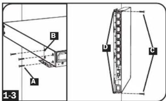
Wall Mounting: Use 3 screws A to attach each of the 2 shorter mounting brackets B to the PDU as shown. Mount the PDU to the wall by inserting 2 or more user-supplied screws C through the mounting brackets D and into secure mounting points.
Installation
1-4 Under-Counter Mounting: Use 3 screws A to attach each of the 2 shorter mounting brackets B to the PDU as shown. Mount the PDU under the counter by inserting 2 or more user-supplied screws C through the mounting brackets D and into secure mounting points.
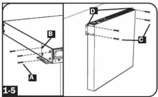
1-5 Reduced-Depth Mounting: Use 3 screws A to attach each of the 2 shorter mounting brackets B to the PDU as shown. Mount the PDU to a stable surface with the outlets facing upward by inserting 2 or more user-supplied screws C through the mounting brackets D and into secure mounting points.
Connecting the PDU
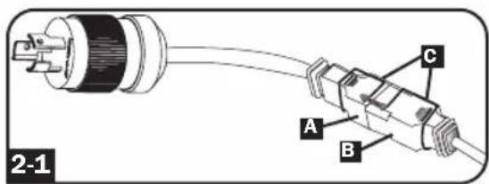
2-1 NEMA Adapter Connection (Optional - PDUMH20HVNET Only): The PDUMH20HVNET includes a plug adapter that adds a NEMA L6-20P plug to the input power cord. Use this adapter only if you will be connecting the PDUMH20HVNET to a NEMA L6-20R outlet. Insert the IEC 60320 C19 connector A of the adapter into the IEC 60320 C20 connector B of the input power cord. Secure the connection with the retention bracket C by using the included bolts to fasten the two halves of the bracket around the connection as shown.
Caution: To avoid the risk of electric shock, ensure that the Neutral (L2) conductor has been identified before connecting the PDU.
Installation

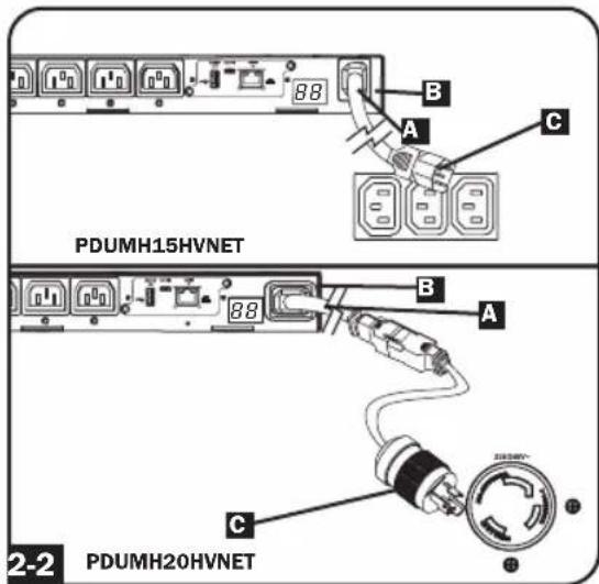
Input Power Cord Connection (Select Models with Unattached Power Cords
Only): Insert the IEC 60320 C19
(PDUMH20HVNET) or IEC 60320 C13
(PDUMH15HVNET) connector A of the input power cord into the IEC 60320
C20 (PDUMH20HVNET) or IEC 60320 C14 (PDUMH15HVNET) inlet B of the
PDU. Connect the other end of the input power cord to a compatible source of AC power, such as a UPS system, PDU or utility outlet. The PDU should be provided with over-current protection:
PDUMH20HVNET should be provided with a maximum 20A branch-rated over-current protection device;
PDUMH15HVNET should be provided with a maximum 15A branch-rated over-current protection device.
Note: The AC power source should not share a circuit with a heavy electrical load (such as an air conditioner or refrigerator).

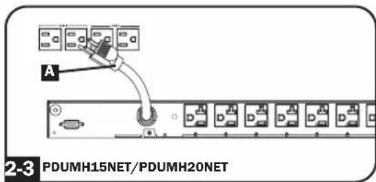
Connect Input Power Cord (PDUMH15NET and PDUMH20NET):
Connect the input plug A to a compatible source of AC power, such as a UPS system, PDU or utility outlet. The PDU should be provided with over-current protection: PDUMH15NET with a maximum 15A branch-rated protection device. PDUMH20NET with a maximum 20A branch-rated protection device.

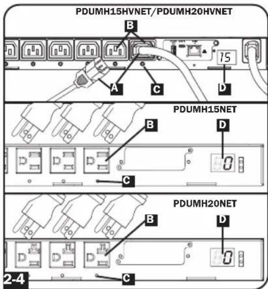
Equipment Power Cord Connection:
Insert the IEC 60320 C14 connectors A of the equipment power cords into the IEC 60320 C13 output receptacles B of the PDU (PDUMH15HVNET and PDUMH20HVNET). Insert power cords into the NEMA 5-15R output receptacles
B (PDUMH15NET) or NEMA 5-15/20R output receptacles B (PDUMH20NET).
The LED near each output receptacle illuminates when the receptacle is ready to distribute live AC power. The digital load meter will display the total connected equipment load in amps.
Networking the PDU
For network configuration instructions, please refer to the WEBCARDLX owner's manual (PN 93358E) included with this product.
Features
natural_image
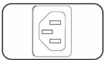
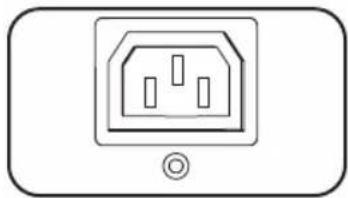
Simple line drawing of an electrical outlet with three slots (no text or symbols)AC Input Power Inlet (Model PDUMH15HVNET): The IEC 60320 C14 inlet connects to the detachable AC Input Power Cord.
natural_image
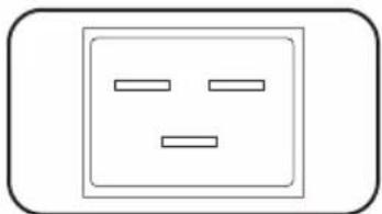
Simple line drawing of a square electrical outlet with two horizontal lines inside, no text or symbols present.AC Input Power Inlet (Model PDUMH20HVNET): The IEC 60320 C20 inlet connects to the detachable AC Input Power Cord.
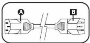
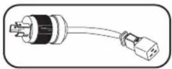
AC Input Power Cord (Model PDUMH15HVNET): The detachable cord has an IEC 60320 C13 connector A and an IEC 60320 C14 connector B
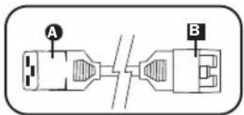
AC Input Power Cord (Model PDUMH20HVNET): The detachable cord has an IEC 60320 C19 connector A and an IEC 60320 C20 connector B
natural_image
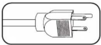
Line drawing of a three-pin electrical plug (no text or symbols)AC Input Power Cord (Model PDUMH15NET): The cord is permanently attached to the PDU and has a NEMA 5-15P plug.
natural_image
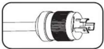
Cross-sectional diagram of a cable or connector with internal components (no text or symbols)AC Input Power Cord (Model PDUMH20NET): The cord is permanently attached to the PDU and has a NEMA L5-20P plug.
natural_image
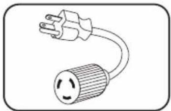
Line drawing of a plug with two connectors (no text or symbols)AC Input Adapter (Model PDUMH20HVNET): The adapter converts the AC input power cord to a NEMA L6-20P plug. The included retention bracket (not shown) secures the connection.
natural_image
Simple line drawing of a voltage outlet with a bulb (no text or symbols)AC Input Adapter (Model PDUMH20NET): The adapter converts NEMA L5-20P input plugs to NEMA 5-20P input plugs.
natural_image
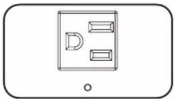
Simple line drawing of a device with three rectangular blocks and a D-shaped element, no text or symbols present.NEMA 5-15R Output Receptacles (PDUMH15NET): During normal operation, the output receptacles distribute AC power to connected equipment. When an outlet is live, the associated LED illuminates.
Features
natural_image
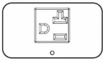
Simple line drawing of a device with three labeled parts (D, L, T) inside a rectangular frame, no text or symbols present.NEMA 5-15/20R Output Receptacles (PDUMH20NET): During normal operation, the output receptacles distribute AC power to connected equipment. When an outlet is live, the associated LED illuminates.
natural_image
Simple line drawing of an electrical outlet with three slots and a base symbol (no text or labels)IEC 60320 C13 Output Receptacles (PDUMH15HVNET & PDUMH20HVNET): During normal operation, the output receptacles distribute AC power to connected equipment. When an outlet is live, the associated LED illuminates.
natural_image
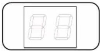
Simple line drawing of two stacked rectangular blocks inside a rounded rectangle (no text or symbols)Digital Load Meter (Ammeter): The total electrical current drawn by connected equipment is displayed on the meter in amperes.
natural_image
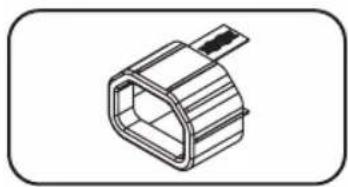
Technical line drawing of a hexagonal connector (no text or symbols)C14 Plug-Lock Insert Sleeve (Optional): Use the included plastic sleeves to secure C13 power cords to C14 inlets. Fit the sleeve over the end of the cord, making sure the pull-tabs remain outside the cord and the fit is secure. To unplug equipment properly, grip both the cord and the insert's tabs at the same time and pull.
natural_image
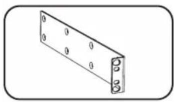
Simple line drawing of a rectangular metal bracket with bolt holes (no text or symbols)Longer Mounting Brackets: Use these brackets to mount the PDU horizontally in a standard rack or rack enclosure. The mounting depth can be adjusted by attaching the brackets to different positions on the PDU.
natural_image
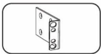
Simple line drawing of a rectangular panel with four circular holes, no text or symbols present.Shorter Mounting Brackets: Use these brackets to mount the PDU in a OU rack, wall or under-counter configuration.
natural_image
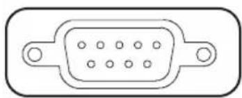
Pure electrical connector diagram without any text or symbolsFactory Port: The port is reserved for configuration by factory authorized personnel only. Do not connect anything to the port.
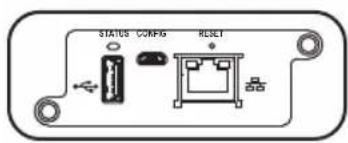
WEBCARDLX: Allows you to operate this PDU as a managed network device, accessible via SNMP network management platform, web browser, SSH or Telnet.
Technical Support
Website: www.tripplite.com/support
E-mail: techsupport@tripplite.com
Warranty and Product Registration
LIMITED WARRANTY
Seller warrants this product, if used in accordance with all applicable instructions, to be free from original defects in material and workmanship for a period of 2 years from the date of initial purchase. If the product should prove defective in material or workmanship within that period, Seller will repair or replace the product, in its sole discretion. Service under this Warranty can only be obtained by your delivering or shipping the product (with all shipping or delivery charges prepaid) to: Tripp Lite, 1111 W. 35th Street, Chicago, IL 60609 USA. Seller will pay return shipping charges. Visit www.tripplite.com/support before sending any equipment back for repair.
THIS WARRANTY DOES NOT APPLY TO NORMAL WEAR OR TO DAMAGE RESULTING FROM ACCIDENT, MISUSE, ABUSE OR NEGLECT. SELLER MAKES NO EXPRESS WARRANTIES OTHER THAN THE WARRANTY EXPRESSLY SET FORTH HEREIN. EXCEPT TO THE EXTENT PROHIBITED BY APPLICABLE LAW, ALL IMPLIED WARRANTIES, INCLUDING ALL WARRANTIES OF MERCHANTABILITY OR FITNESS, ARE LIMITED IN DURATION TO THE WARRANTY PERIOD SET FORTH ABOVE; AND THIS WARRANTY EXPRESSLY EXCLUDES ALL INCIDENTAL AND CONSEQUENTIAL DAMAGES. (Some states do not allow limitations on how long an implied warranty lasts, and some states do not allow the exclusion or limitation of incidental or consequential damages, so the above limitations or exclusions may not apply to you. This Warranty gives you specific legal rights, and you may have other rights which vary from jurisdiction to jurisdiction).
WARNING: The individual user should take care to determine prior to use whether this device is suitable, adequate or safe for the use intended. Since individual applications are subject to great variation, the manufacturer makes no representation or warranty as to the suitability or fitness of these devices for any specific application.
PRODUCT REGISTRATION
Visit www.triplite.com/warranty today to register your new Tripp Lite product. You'll be automatically entered into a drawing for a chance to win a FREE Tripp Lite product!*
* No purchase necessary. Void where prohibited. Some restrictions apply. See website for details.
FCC Notice, Class A
This device complies with part 15 of the FCC Rules. Operation is subject to the following two conditions: (1) This device may not cause harmful interference, and (2) this device must accept any interference received, including interference that may cause undesired operation.
Note: This equipment has been tested and found to comply with the limits for a Class A digital device, pursuant to part 15 of the FCC Rules. These limits are designed to provide reasonable protection against harmful interference when the equipment is operated in a commercial environment. This equipment generates, uses, and can radiate radio frequency energy and, if not installed and used in accordance with the instruction manual, may cause harmful interference to radio communications. Operation of this equipment in a residential area is likely to cause harmful interference in which case the user will be required to correct the interference at his own expense. The user must use shielded cables and connectors with this equipment. Any changes or modifications to this equipment not expressly approved by Tripp Lite could void the user's authority to operate this equipment.
Regulatory Compliance Identification Numbers
For the purpose of regulatory compliance certifications and identification, your Tripp Lite product has been assigned a unique series number. The series number can be found on the product nameplate label, along with all required approval markings and information. When requesting compliance information for this product, always refer to the series number. The series number should not be confused with the marking name or model number of the product.
WEEE Compliance Information for Tripp Lite Customers and Recyclers (European Union)

Under the Waste Electrical and Electronic Equipment (WEEE) Directive and implementing regulations, when customers buy new electrical and electronic equipment from Tripp Lite they are entitled to:
- Send old equipment for recycling on a one-for-one, like-for-like basis (this varies depending on the country)
- Send the new equipment back for recycling when this ultimately becomes waste
Tripp Lite has a policy of continuous improvement. Specifications are subject to change without notice.

TrippLite.Eaton.com/support
natural_image
Simple line drawing of an electrical outlet with three slots (no text or symbols)natural_image
Simple line drawing of a square electrical outlet with two horizontal lines inside, no text or symbols present.natural_image
Line drawing of a three-pin electrical plug (no text or symbols)natural_image
Cross-sectional diagram of a cable or connector with internal components (no text or symbols)natural_image
Illustration of a black and white electrical plug with a terminal connector (no text or symbols)natural_image
Simple line drawing of an open electrical plug with a circular fuse (no text or symbols)natural_image
Simple line drawing of a rectangular device with three internal compartments and a circular button at the bottom (no text or symbols)natural_image
Simple line drawing of a device with three labeled components (D, L, T) and a circular button at the bottom right (no text or symbols)natural_image
Simple line drawing of an electrical outlet with three slots and a circular button at the bottom (no text or symbols)natural_image
Two identical 3D rectangular blocks inside a rounded rectangle, no text or symbols present.natural_image
Technical line drawing of a hexagonal connector or connector (no text or symbols)natural_image
Isometric view of a rectangular metal bracket with bolt holes (no text or symbols)natural_image
Simple line drawing of a rectangular frame with four circular holes, no text or symbols present.natural_image
Line drawing of a rectangular electronic component with a central port and two side ports (no text or symbols)Website: www.tripplite.com/support
Correo Electrónico: techsupport@tripplite.com