
GTS 18V216 Professional - Saw BOSCH - Free user manual and instructions
Find the device manual for free GTS 18V216 Professional BOSCH in PDF.
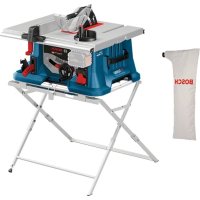



| Product type | Cordless table saw |
| Brand | Bosch |
| Model | GTS 18V216 Professional |
| Category | Saw |
| Power source | 18 V lithium-ion battery (compatible with GBA 18V… and ProCORE18V…) |
| No-load speed | 4500 rpm |
| Saw blade diameter | 216 mm (bore 30 mm or 25.4 mm depending on variant) |
| Maximum cutting depth | 70 mm (bevel angle 0°), 50 mm (bevel angle 45°) |
| Miter angle range (horizontal) | -30° to +30° (with miter stop) |
| Bevel angle range (vertical) | 0° to 45° |
| Dimensions (L × W × H) | 658 × 332 × 553 mm |
| Weight (according to EPTA 01:2014) | 20.5 – 21.6 kg (depending on battery used) |
| Saw table with extension | Right extension up to 29 cm additional |
| Safety devices | Protective guard, riving knife, anti-kickback, emergency stop, restart protection |
| Main functions | Rip cuts and cross cuts, miter cuts, bevel cuts, grooving (with accessories) |
| Sound level | Sound pressure 81 dB(A) / Sound power 94 dB(A) (uncertainty K=3 dB) |
| Maintenance and cleaning | Disconnect the battery before any operation; regularly clean the ventilation slots and the lower blade guard; use a brush or compressed air |
| Spare parts and repairability | Bosch saw blades (wood, aluminum, laminate); work support GTA 560/60W; Bosch after-sales service |
Frequently Asked Questions - GTS 18V216 Professional BOSCH
User questions about GTS 18V216 Professional BOSCH
0 question about this device. Answer the ones you know or ask your own.
Ask a new question about this device
Download the instructions for your Saw in PDF format for free! Find your manual GTS 18V216 Professional - BOSCH and take your electronic device back in hand. On this page are published all the documents necessary for the use of your device. GTS 18V216 Professional by BOSCH.
USER MANUAL GTS 18V216 Professional BOSCH
General Power Tool Safety Warnings
WARNING
Read all safety warnings, instructions, illustrations and specifications.
tions provided with this power tool. Failure to follow all instructions listed below may result in electric shock, fire and/or serious injury.
Save all warnings and instructions for future reference.
The term "power tool" in the warnings refers to your mains-operated (corded) power tool or battery-operated (cordless) power tool.
Keep work area clean and well lit. Cluttered or dark areas invite accidents.
- Keep work area clean and well lit. Cluttered or dark areas invite accidents.
- Do not operate power tools in explosive atmospheres, such as in the presence of flammable liquids, gases or dust. Power tools create sparks which may ignite the dust or fumes.
- Keep children and bystanders away while operating a power tool. Distractions can cause you to lose control.
Power tool plugs must match the outlet. Never modify the plug in any way. Do not use any adapter plugs with earthed (grounded) power tools. Unmodified plugs and matching outlets will reduce risk of electric shock. Avoid body contact with earthed or grounded surfaces, such as pipes, radiators, ranges and refrigerators. There is an increased risk of electric shock if your body is earthed or grounded. Do not expose power tools to rain or wet conditions. Water entering a power tool will increase the risk of electric shock. Do not abuse the cord. Never use the cord for carrying, pulling or unplugging the power tool. Keep cord away from heat, oil, sharp edges or moving parts. Damaged or entangled cords increase the risk of electric shock. When operating a power tool outdoors, use an extension cord suitable for outdoor use. Use of a cord suitable for outdoor use reduces the risk of electric shock. If operating a power tool in a damp location is unavoidable, use a residual current device (RCD) protected supply. Use of an RCD reduces the risk of electric shock.
Power tool plugs must match the outlet. Never modify the plug in any way. Do not use any adapter plugs with earthed (grounded) power tools. Unmodified plugs and matching outlets will reduce risk of electric shock. Avoid body contact with earthed or grounded surfaces, such as pipes, radiators, ranges and refrigerators. There is an increased risk of electric shock if your body is earthed or grounded. Do not expose power tools to rain or wet conditions. Water entering a power tool will increase the risk of electric shock. Do not abuse the cord. Never use the cord for carrying, pulling or unplugging the power tool. Keep cord away from heat, oil, sharp edges or moving parts. Damaged or entangled cords increase the risk of electric shock. When operating a power tool outdoors, use an extension cord suitable for outdoor use. Use of a cord suitable for outdoor use reduces the risk of electric shock. If operating a power tool in a damp location is unavoidable, use a residual current device (RCD) protected supply. Use of an RCD reduces the risk of electric shock.
Stay alert, watch what you are doing and use common sense when operating a power tool. Do not use a power tool while you are tired or under the influence of drugs, alcohol or medication. A moment of inattention while operating power tools may result in serious personal injury.
Stay alert, watch what you are doing and use common sense when operating a power tool. Do not use a power tool while you are tired or under the influence of drugs, alcohol or medication. A moment of inattention while operating power tools may result in serious personal injury.
tion while operating power tools may result in serious personal injury.
Use personal protective equipment. Always wear eye protection. Protective equipment such as a dust mask, non-skid safety shoes, hard hat, or hearing protection used for appropriate conditions will reduce personal injuries. Prevent unintentional starting. Ensure the switch is in the off-position before connecting to a power source and/or battery pack, picking up, or carrying the tool. Carrying power tools with your finger on the switch or energizing power tools that have the switch on invites accidents. Remove any adjusting key or wrench before turning the power tool on. A wrench or a key left attached to a rotating part of the power tool may result in personal injury. Do not overreach. Keep proper footing and balance at all times. This enables better control of the power tool in unexpected situations. Dress properly. Do not wear loose clothing or jewelry. Keep your hair and clothing away from moving parts. Loose clothes, jewelry, or long hair can be caught in moving parts. If devices are provided for the connection of dust extraction and collection facilities, ensure these are connected and properly used. Use of dust collection can reduce dust-related hazards. Do not let familiarity gained from frequent use of tools allow you to become complacent and ignore tool safety principles. A careless action can cause severe injury within a fraction of a second.
Power tool use and care
Do not force the power tool. Use the correct power tool for your application. The correct power tool will do the job better and safer at the rate for which it was designed. Do not use the power tool if the switch does not turn it on and off. Any power tool that cannot be controlled with the switch is dangerous and must be repaired. Disconnect the plug from the power source and/or remove the battery pack, if detachable, from the power tool before making any adjustments, changing accessories, or storing power tools. Such preventive safety measures reduce the risk of starting the power tool accidentally. Store idle power tools out of the reach of children and do not allow persons unfamiliar with the power tool or these instructions to operate the power tool. Power tools are dangerous in the hands of untrained users. Maintain power tools and accessories. Check for misalignment or binding of moving parts, breakage of parts, and any other condition that may affect the power tool's operation. If damaged, have the power tool repaired before use. Many accidents are caused by poorly maintained power tools.
- Keep cutting tools sharp and clean. Properly maintained cutting tools with sharp cutting edges are less likely to bind and are easier to control. Use the power tool, accessories, and tool bits etc. in accordance with these instructions, taking into account the working conditions and the work to be performed. Use of the power tool for operations different from those intended could result in a hazardous situation.
- Keep handles and grasping surfaces dry, clean and free from oil and grease. Slippery handles and grasping surfaces do not allow for safe handling and control of the tool in unexpected situations.
Battery tool use and care
- Recharge only with the charger specified by the manufacturer. A charger that is suitable for one type of battery pack may create a risk of fire when used with another battery pack.
- Use power tools only with specifically designated battery packs. Use of any other battery packs may create a risk of injury and fire.
- When battery pack is not in use, keep it away from other metal objects, like paper clips, coins, keys, nails, screws or other small metal objects, that can make a connection from one terminal to another. Shorting the battery terminals together may cause burns or a fire. Under abusive conditions, liquid may be ejected from the battery; avoid contact. If contact accidentally occurs, flush with water. If liquid contacts eyes, additionally seek medical help. Liquid ejected from the battery may cause irritation or burns. Do not use a battery pack or tool that is damaged or modified. Damaged or modified batteries may exhibit unpredictable behaviour resulting in fire, explosion or risk of injury. Do not expose a battery pack or tool to fire or excessive temperature. Exposure to fire or temperature above 130°C may cause explosion. Follow all charging instructions and do not charge the battery pack or tool outside the temperature range specified in the instructions. Charging improperly or at temperatures outside the specified range may damage the battery and increase the risk of fire.
Service
Have your power tool serviced by a qualified repair person using only identical replacement parts. This will ensure that the safety of the power tool is maintained. Never service damaged battery packs. Service of battery packs should only be performed by the manufacturer or authorized service providers.
Safety instructions for table saws
Guarding related warnings
- Keep guards in place. Guards must be in working order and be properly mounted. A guard that is loose,
damaged, or is not functioning correctly must be repaired or replaced.
Always use saw blade guard and riving knife for every through-cutting operation. For through-cutting operations where the saw blade cuts completely through the thickness of the workpiece, the guard and other safety devices help reduce the risk of injury. Immediately reattach the guarding system after completing an operation (such as rabbeting) which requires removal of the guard and/or riving knife. The guard and riving knife help to reduce the risk of injury. Make sure the saw blade is not contacting the guard, riving knife or the workpiece before the switch is turned on. Inadvertent contact of these items with the saw blade could cause a hazardous condition. Adjust the riving knife as described in this instruction manual. Incorrect spacing, positioning and alignment can make the riving knife ineffective in reducing the likelihood of kickback. For the riving knife to work, it must be engaged in the workpiece. The riving knife is ineffective when cutting workpieces that are too short to be engaged with the riving knife. Under these conditions a kickback cannot be prevented by the riving knife. Use the appropriate saw blade for the riving knife. For the riving knife to function properly, the saw blade diameter must match the appropriate riving knife and the body of the saw blade must be thinner than the thickness of the riving knife and the cutting width of the saw blade must be wider than the thickness of the riving knife.
Cutting procedures warnings
WARNING: Never place your fingers or hands in the vicinity or in line with the saw blade. A moment of inattention or a slip could direct your hand towards the saw blade and result in serious personal injury. Feed the workpiece into the saw blade only against the direction of rotation. Feeding the workpiece in the same direction that the saw blade is rotating above the table may result in the workpiece, and your hand, being pulled into the saw blade. Never use the mitre gauge to feed the workpiece when ripping and do not use the rip fence as a length stop when cross cutting with the mitre gauge. Guiding the workpiece with the rip fence and the mitre gauge at the same time increases the likelihood of saw blade binding and kickback. When ripping, always apply the workpiece feeding force between the fence and the saw blade. Use a push stick when the distance between the fence and the saw blade is less than 150 mm and use a push block when this distance is less than 50 mm. "Work helping" devices will keep your hand at a safe distance from the saw blade. Use only the push stick provided by the manufacturer or constructed in accordance with the instructions.
This push stick provides sufficient distance of the hand from the saw blade.
- Never use a damaged or cut push stick. A damaged push stick may break, causing your hand to slip into the saw blade. Do not perform any operation "freehand". Always use either the rip fence or the mitre gauge to position and guide the workpiece. "Freehand" means using your hands to support or guide the workpiece, in lieu of a rip fence or mitre gauge. Freehand sawing leads to misalignment, binding, and kickback.
- Never reach around or over a rotating saw blade. Reaching for a workpiece may lead to accidental contact with the moving saw blade.
- Provide auxiliary workpiece support to the rear and/or sides of the saw table for long and/or wide workpieces to keep them level. A long and/or wide workpiece has a tendency to pivot on the table's edge, causing loss of control, saw blade binding, and kickback. Feed the workpiece at an even pace. Do not bend or twist the workpiece. If jamming occurs, turn the tool off immediately, unplug the tool, then clear the jam. Jamming the saw blade by the workpiece can cause kickback or stall the motor. Do not remove pieces of cut-off material while the saw is running. The material may become trapped between the fence or inside the saw blade guard and the saw blade, pulling your fingers into the saw blade. Turn the saw off and wait until the saw blade stops before removing material. Use an auxiliary fence in contact with the table top when ripping workpieces less than 2 mm thick. A thin workpiece may wedge under the rip fence and create a kickback.
Kickback causes and related warnings
Kickback is a sudden reaction of the workpiece due to a pinched, jammed saw blade or misaligned line of cut in the workpiece with respect to the saw blade, or when a part of the workpiece binds between the saw blade and the rip fence or other fixed object.
Most frequently during kickback, the workpiece is lifted from the table by the rear portion of the saw blade and is propelled towards the operator.
Kickback is the result of saw misuse and/or incorrect operating procedures or conditions and can be avoided by taking proper precautions as given below.
- Never stand directly in line with the saw blade. Always position your body on the same side of the saw blade as the fence. Kickback may propel the workpiece at high velocity towards anyone standing in front and in line with the saw blade.
- Never reach over or in back of the saw blade to pull or to support the workpiece. Accidental contact with the saw blade may occur or kickback may drag your fingers into the saw blade.
Never hold and press the workpiece that is being cut off against the rotating saw blade. Pressing the workpiece being cut off against the saw blade will create a binding condition and kickback. Align the fence to be parallel with the saw blade. A misaligned fence will pinch the workpiece against the saw blade and create kickback. Use a featherboard to guide the workpiece against the table and fence when making non-through cuts such as rabbeting. A featherboard helps to control the workpiece in the event of a kickback. Support large panels to minimise the risk of saw blade pinching and kickback. Large panels tend to sag under their own weight. Support(s) must be placed under all portions of the panel overhanging the table top. Use extra caution when cutting a workpiece that is twisted, knotted, warped or does not have a straight edge to guide it with a litre gauge or along the fence. A warped, knotted, or twisted workpiece is unstable and causes misalignment of the kerf with the saw blade, binding and kickback. - Never cut more than one workpiece, stacked vertically or horizontally. The saw blade could pick up one or more pieces and cause kickback. When restarting the saw with the saw blade in the workpiece, centre the saw blade in the kerf so that the saw teeth are not engaged in the material. If the saw blade binds, it may lift up the workpiece and cause kickback when the saw is restarted. - Keep saw blades clean, sharp, and with sufficient set. Never use warped saw blades or saw blades with cracked or broken teeth. Sharp and properly set saw blades minimise binding, stalling and kickback.
Table saw operating procedure warnings
Turn off the table saw and disconnect the battery pack when removing the table insert, changing the saw blade or making adjustments to the riving knife or blade guard, and when the machine is left unattended. Precautionary measures will avoid accidents. - Never leave the table saw running unattended. Turn it off and don't leave the tool until it comes to a complete stop. An unattended running saw is an uncontrolled hazard. Locate the table saw in a well-lit and level area where you can maintain good footing and balance. It should be installed in an area that provides enough room to easily handle the size of your workpiece. Cramped, dark areas, and uneven slippery floors invite accidents. Frequently clean and remove sawdust from under the saw table and/or the dust collection device. Accumulated sawdust is combustible and may self-ignite. The table saw must be secured. A table saw that is not properly secured may move or tip over. - Remove tools, wood scraps, etc. from the table before the table saw is turned on. Distraction or a potential jam can be dangerous.
Always use saw blades with correct size and shape (diamond versus round) of arbour holes. Saw blades that do not match the mounting hardware of the saw will run off-centre, causing loss of control. Never use damaged or incorrect saw blade mounting means such as flanges, saw blade washers, bolts or nuts. These mounting means were specially designed for your saw, for safe operation and optimum performance. Never stand on the table saw, do not use it as a stepping stool. Serious injury could occur if the tool is tipped or if the cutting tool is accidentally contacted. Make sure that the saw blade is installed to rotate in the proper direction. Do not use grinding wheels, wire brushes, or abrasive wheels on a table saw. Improper saw blade installation or use of accessories not recommended may cause serious injury.
Additional safety warnings
When mounting the saw blade, wear protective gloves. This poses a risk of injury. Do not use HSS saw blades. Such saw blades can easily break. Only use saw blades that match the specifications given in this operating manual and that are tested and marked in accordance with EN 847-1. Never use the tool without the table insert. Replace table insert if defective. Without flawless table inserts, injuries are possible from the saw blade. Keep your work area clean. Material mixtures are particularly hazardous. Light metal dust may catch fire or explode. Choose the saw blade suited to the material you want to work on. Only use saw blades that are recommended by the power tool manufacturer and are suitable for using on the material you want to saw. Only advance the workpiece towards the saw blade when it is running. Otherwise there is a risk of kickback occurring if the saw blade catches in the workpiece. In case of damage and improper use of the battery, vapours may be emitted. The battery can set alight or explode. Ensure the area is well ventilated and seek medical attention should you experience any adverse effects. The vapours may irritate the respiratory system. Do not open the battery. There is a risk of short-circuiting. The battery can be damaged by pointed objects such as nails or screwdrivers or by force applied externally. An internal short circuit may occur, causing the battery to burn, smoke, explode or overheat. Only use the battery with products from the manufacturer. This is the only way in which you can protect the battery against dangerous overload.
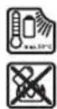
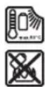
Protect the battery against heat, e.g. against continuous intense sunlight, fire, dirt, water and moisture. There is a risk of explosion and short-circuiting.
Symbols
The following symbols may be important for the operation of your power tool. Please take note of these symbols and their meaning. Correctly interpreting the symbols will help you to operate the power tool more effectively and safely.
Symbols and their meaning

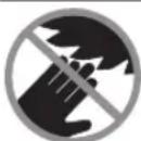
Keep hands away from the cutting area while the power tool is running. Contact with the saw blade can lead to injuries.
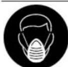
Wear a dust mask.

Wear hearing protection. Exposure to noise can cause hearing loss.

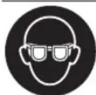
Wear safety goggles.
3601M44000 3601M440K0 3601M44040
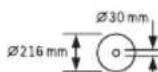
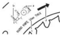
If it is necessary to use reducers, ensure that the dimensions of the reducer are suitable for the base blade thickness and the saw blade hole diameter, as well as the tool spindle diameter. Wherever possible, use the reducers provided with the saw blade.
3601M44OB0
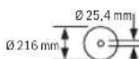
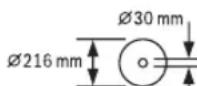
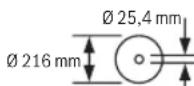
The saw blade diameter must match the information specified on the symbol.
3601M44000 3601M44OK0 3601M44040
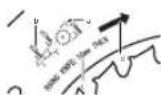
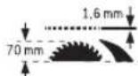
a The saw blade must be no more than 216 mm in diameter. b When changing the saw blade, make sure that the cutting width is no smaller than 1.7 mm and the base blade thickness is no larger than 1.5 mm. Otherwise, there is a risk that the riving knife will hook into the workpiece.
c The riving knife is 1.6 mm thick.
d The cutting direction of the teeth (direction of the arrow on the saw blade)
Symbols and their meaning
must match the direction of the arrow on the riving knife.
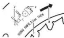
3601M440B0
a The saw blade must be no more than 216 mm in diameter.
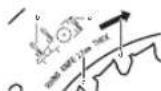
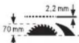
b When changing the saw blade, make sure that the cutting width is no smaller than 2.3 mm and the base blade thickness is no larger than 2.1 mm. Otherwise, there is a risk that the riving knife will hook into the workpiece.
c The riving knife is 2.2 mm thick.
d The cutting direction of the teeth (direction of the arrow on the saw blade) must match the direction of the arrow on the riving knife.
3601M44000
The riving knife is 1.6 mm thick.
3601M440K0
The maximum possible workpiece height is 70 mm.
3601M44040
The riving knife is 2.2 mm thick.
3601M440B0
The maximum possible workpiece height is 70 mm.
Left-hand side:
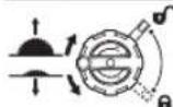
Indicates the direction of rotation of the crank for lowering (transport position) and raising (work position) the saw blade.
Right-hand side:
Indicates the position of the locking lever for securing the saw blade and setting the bevel angle (saw blade can be swivelled).

The CE mark provides confirmation from the manufacturer that the power tool complies with the applicable EU Directives.
Product Description and Specifications

Read all the safety and general instructions.
Failure to observe the safety and general instructions may result in electric shock, fire and/or serious injury.
Please observe the illustrations at the beginning of this operating manual.
Intended use
The power tool is a stationary machine for cutting in a straight line with and against the grain in hardwood, softwood, chipboard and fibreboard. Mitre angles of -30° to +30° as well as bevel angles of 0° to 45° are possible.
It is also possible to saw aluminium profiles and plastic using the appropriate saw blades.
Product Features
The numbering of the product features refers to the diagram of the power tool on the graphics page.
(1) Scale for spacing between saw blade and parallel guide (2) Angle guide (3) Protective cover (4) Riving knife (5) Parallel guide (6) Saw table expansion (7) Angle guide storage compartment (8) Mounting holes (9) Ring spanner (23 mm; 13 mm) (10) Hex key (5 mm) (11) Bracket for storing the protective cover (12) Push stick (13) Clamping handle for saw table expansion (14) Hand wheel (15) Crank for raising and lowering the saw blade (16) On/off switch (17) Battery (18) Stop for 45° bevel angle. (19) Scale for bevel angles (20) Locking lever for setting the bevel angle (21) Angle indicator (vertical) (22) Stop for 0° bevel angle (23) Saw table. (24) Adjusting screw for adjusting the clamping force of the parallel guide (25) Table insert (26) Saw blade (27) Guide groove for parallel guide (28) Battery release button (29) Carrying handle (30) Guide groove for angle guide (31) Dust extraction adapter (32) V guide groove on the saw table for the parallel guide (33) Base grid (34) Locking screw for base grid (35) Clamping lever/clamp markings
(36) Clamping lever for riving knife (37) Positioning pins for riving knife (38) Table insert locking screw (39) Clamping lever for protective cover (40) Guide pin for protective cover (41) Clamping handle for parallel guide (42) V guide for parallel guide (43) Additional parallel guide (44) "Additional parallel guide" fastening set (45) Guide rail for angle guide (46) Lower saw blade cover (47) Tab for lower saw blade cover (48) Gripping hole for lifting the table insert (49) Clamping nut (50) Spindle locking lever (51) Clamping flange (52) Mounting flange (53) Tool spindle (54) Locking knob for all metre angles
(55) Angle indicator on the angle guide (56) Scale display (57) Saw table spacing indicator (58) Cross-head screw for setting the 0° stop (59) Screw for bevel angle indicator (60) Cross-head screw for setting the 45° stop (61) Hex socket screws (5 mm) on the front for adjusting the parallelism of the saw blade (62) Hex socket screws (5 mm) on the rear for adjusting the parallelism of the saw blade (63) Screw for saw table spacing indicator (64) Hex socket screws (5 mm) for adjusting the parallelism of the parallel guide (65) Screw for parallel guide spacing indicator (66) Adjusting screws for table insert (67) Push stick storage compartment (68) Hex key storage compartment (69) Ring spanner storage compartment
a) Accessories shown or described are not included with the product as standard. You can find the complete selection of accessories in our accessories range.
Technical Data
Table saw GTS 18V-216 GTS 18V-216
| Article number | 3 601 M44 0003 601 M44 0403 601 M44 0KO | 3 601 M44 0BO | |
| Rated voltage V= 18 18 | |||
| No-load speedA) | min-1 | 4500 4500 | |
| Starting current limitation ● ● | |||
| Weight according to EPTA-Procedure 01:2014B) | kg 20,5-21,6 20,5-21,6 | ||
| Recommended ambient temperature during charging | °C 0...+35 0...+35 | ||
| Permitted ambient temperature during operationC) and during storage | °C -20...+50 -20...+50 | ||
| Compatible rechargeable batteries GBA 18V... | ProCORE18V... | GBA 18V...ProCORE18V... | |
| Recommended rechargeable batteries for maximum performance | ProCORE18V... ≥ 5,5 Ah | ProCORE18V... ≥ 5,5 Ah | |
| Recommended chargers GAL 18... | GAX 18... | GAX 18... | |
| GAL 36... | GAL 36... |
Dimensions (including detachable parts of the tool)
Width x depth x height mm 658 x 332 x 553 658 x 332 x 553
Dimensions of suitable saw blades
| Saw blade diameter mm | 216 | 216 | |
| Base blade thickness | mm | <1,5 | 1,5-2,1 |
| Min. tooth thickness/offset | mm | >1,7 | >2,3 |
Table saw GTS 18V-216 GTS 18V-216
Hole diameter mm 30 25.4
A) Measured at 20 - 25°C with rechargeable battery ProCORE18V 12.0Ah. B) Depends on battery in use C) Limited performance at temperatures < 0°C Maximum workpiece dimensions: (see "Maximum workpiece dimensions", page 26)
Noise information
Noise emission values determined according to EN 62841-3-1.
Typically, the A-weighted noise level of the power tool is: Sound pressure level 81 dB(A); sound power level 94 dB(A). Uncertainty K = 3 dB.
Wear hearing protection!
The noise emission value given in these instructions has been measured in accordance with a standardised measuring procedure and may be used to compare power tools. It may also be used for a preliminary estimation of noise emissions.
The noise emission value given represents the main applications of the power tool. However, if the power tool is used for other applications, with different application tools or is poorly maintained, the noise emission value may differ. This may significantly increase noise emissions over the total working period.
To estimate noise emissions accurately, the times when the tool is switched off, or when it is running but not actually being used, should also be taken into account. This may significantly reduce noise emissions over the total working period.
Assembly
- Remove the battery from the power tool before carrying out work on the power tool (e.g. maintenance, changing tool, etc.). The battery should also be removed for transport and storage. There is risk of injury from unintentionally pressing the on/off switch.
Items included
Check to ensure that all the parts listed below have been supplied before using the power tool for the first time:
- Table saw with fitted saw blade (26) and riving knife (4) Angle guide (2)
- Parallel guide (5)
- Additional parallel guide (43)
- "Additional parallel guide" fastening set (44) (2 fastening screws, 2 washers, 2 wing nuts)
- Protective cover (3)
- Hex key (10)
- Ring spanner (9) with slotted screwdriver tip
- Push stick (12)
- Table insert (25)
Note: Check the power tool for possible damage. Before continuing to use the power tool, carefully check that
all protective devices or slightly damaged parts are working perfectly and according to specifications. Check that the moving parts are working perfectly and without jamming; check whether any parts are damaged. All parts must be fitted correctly and all the conditions necessary to ensure smooth operation must be met.
If the protective devices or any parts become damaged, you must have them properly repaired or replaced by an authorised service centre.
Extra tools required (not included in the delivery):
- Cross-headed screwdriver Angle gauge
Fitting individual components
- Carefully remove all parts included in the delivery from their packaging.
- Remove all packing material from the power tool and the accessories provided.
- Turn the locking screws (34) as far as possible in the "Unlock" direction using the tip of the ring spanner (9) and open the base grid (33) (see figure a).
Remove the packing material under the motor block.
The following tool elements are attached directly to the tool housing: Push stick (12), ring spanner (9), hex key (10), parallel guide (5), angle guide (2), extraction adapter (31), additional parallel guide (43) with fastening set (44), protective cover (3). - If you require one of these parts, remove it carefully from its storage location.
Positioning the riving knife (see figures b1-b2)
Note: If necessary, clean all parts to be fitted before you position them.
Turn the crank (15) clockwise as far as possible so that the saw blade (26) is in the highest possible position above the saw table. - Release the clamping lever (36) clockwise until it points upwards. - Slide the riving knife (4) towards the clamping lever (36) until it can be pulled upwards. - Pull the riving knife all the way up until it is positioned exactly over the centre of the saw blade. - Allow both pins (37) to engage in the lower bore holes in the riving knife and then retighten the clamping lever (36).
The markings (35) on the clamp and clamping lever (36) must be aligned as shown.
22 | English
Fitting the table insert (see figure c)
- Place the table insert (25) over the riving knife (4) and into the tool chamber.
- Turn the locking screw (38) as far as it will go in the "Lock" direction using the tip of the ring spanner (9).
The front side of the table insert (25) must lie flush with or a little below the saw table; the rear must lie flush with or a little above the saw table.
Fitting the protective cover (see figures d1-d2)
Note: Only fit the protective cover when the riving knife is in the top position directly over the centre of the saw blade (see figure b2). Do not fit the protective cover when the riving knife is in the bottom position (position when delivered/ position for sawing grooves) (see figure b1).
- Loosen the clamping lever (39) and remove the protective cover (3) from the bracket (11).
- Hold the saw blade guard (upper metal rail) of the protective cover (3) with one hand, while using the other hand to move the clamping lever (39) up.
- Push the guide pin (40) backwards into the groove on the riving knife (4).
- Move the protective cover (3) down until the saw blade guard (upper metal rail) is parallel with the surface of the saw table (23).
- Push the clamping lever (39) down. The clamping lever must be felt and heard to engage; the protective cover (3) must be securely and safely fitted.
Always check that the blade guard can move properly before use. Do not use the power tool if the blade guard cannot move freely and does not close immediately.
Fitting the parallel guide (see figure e)
The parallel guide (5) can be positioned on either the left or the right of the saw blade.
- Loosen the clamping handle (41) of the parallel guide (5). This lightens the load on the V guide (42).
- First insert the parallel guide with the V guide into the guide groove (32) of the saw table. Then position the parallel guide in the front guide groove (27) of the saw table. The parallel guide can now be moved freely.
- To secure the parallel guide, push the clamping handle (41) down.
Fitting the additional parallel guide (see figure f)
To saw narrow workpieces and bevel angles, you must fit the additional parallel guide (43) on the parallel guide (5).
The additional parallel guide can be fitted on the left or right of the parallel guide (5) as required.
Use the "additional parallel guide" fastening set (44) (two fastening screws, two washers, two wing nuts) for fitting the guide.
- Slide the fastening screws through the lateral holes on the parallel guide (5).
- The heads of the screws are used to guide the additional parallel guide.
- Slide the additional parallel guide (43) over the heads of the fastening screws.
- Place the washers on the fastening screws and tighten the screws using the wing nuts.
Fitting the angle guide (see figure g)
- Push the rail (45) of the angle guide (2) into one of the guide grooves (30) provided in the saw table.
Battery Charging
Use only the chargers listed in the technical data. Only these chargers are matched to the lithium-ion battery of your power tool.
Note: The battery is supplied partially charged. To ensure full battery capacity, fully charge the battery in the charger before using your power tool for the first time.
The lithium-ion battery can be charged at any time without reducing its service life. Interrupting the charging process does not damage the battery.
The lithium-ion battery is protected against deep discharge by the "Electronic Cell Protection (ECP)". When the battery is discharged, the power tool is switched off by means of a protective circuit: The application tool no longer rotates.
Do not continue to press the On/Off switch after the power tool has automatically switched off. The battery can be damaged.
Follow the instructions on correct disposal.
Removing the Battery
The battery (17) is equipped with two locking levels to prevent the battery from falling out if the battery release button (28) is pressed unintentionally. The battery is held in place by a spring when fitted in the power tool.
- To remove the battery (17), press the release button (28) and pull the battery out of the power tool. Do not use force to do this.
Battery charge indicator
The green LEDs on the battery charge indicator indicate the state of charge of the battery. For safety reasons, it is only possible to check the state of charge when the power tool is not in operation.
Press the button for the battery charge indicator or to show the state of charge. This is also possible when the battery is removed.
If no LED lights up after pressing the button for the battery charge indicator, then the battery is defective and must be replaced.
Battery model GBA 18V...


LEDs Capacity
3x continuous green light: 60-100% | 2x continuous green light: 30-60%
LEDs Capacity
1x continuous green light: 5-30% | 1x flashing green light: 0-5%
Battery model ProCORE18V...

LEDs Capacity
5x continuous green light: 80-100% | 4x continuous green light: 60-80% | 3x continuous green light: 40-60% | 2x continuous green light: 20-40% | 1x continuous green light: 5-20% | 1x flashing green light: 0-5%
Stationary or flexible mounting
To ensure safe handling, the power tool must be mounted on a flat, stable work surface (e.g., work bench) before use.
Mounting on a work surface (see figure h)
- Use suitable screw fasteners to secure the power tool to the work surface. The holes (8) are used for this purpose.
Mounting on a Bosch saw stand (see figure i)
Thanks to their height-adjustable legs, Bosch saw stands (e.g., GTA 560) provide firm support for the power tool on any surface.
Read all the warnings and instructions included with the saw stand. Failure to observe the warnings and follow instructions may result in electric shock, fire and/or serious injury. - Assemble the saw stand properly before mounting the power tool. Correct assembly is important to prevent the risk of collapsing. - Mount the power tool on the saw stand in the transport position.
Dust/chip extraction
The dust from materials such as lead paint, some types of wood, minerals and metal can be harmful to human health. Touching or breathing in this dust can trigger allergic reactions and/or cause respiratory illnesses in the user or in people in the near vicinity.
Certain dusts, such as oak or beech dust, are classified as carcinogenic, especially in conjunction with wood treatment additives (chromate, wood preservative). Materials containing asbestos may only be machined by specialists.
- Use a dust extraction system that is suitable for the material wherever possible.
- Provide good ventilation at the workplace.
- It is advisable to wear a P2 filter class breathing mask.
The regulations on the material being machined that apply in the country of use must be observed.
- Avoid dust accumulation at the workplace. Dust can easily ignite.
The dust/chip extraction system can be blocked by dust, chips or fragments of the workpiece.
- Switch the power tool off and remove the battery.
- Wait until the saw blade has come to a complete stop.
- Determine the cause of the blockage and eliminate it. To prevent the risk of fire when sawing aluminium, empty the lower saw blade cover and do not use chip extraction.
Cleaning the lower saw blade cover (see figure j)
You can open the lower saw blade cover (46) to remove workpiece fragments and large chips.
- Switch the power tool off and remove the battery from the power tool.
- Wait until the saw blade has come to a complete stop.
- Tilt the power tool sideways.
- Open the base grid (33) (see figure a). Gently pull apart the tabs (47) of the lower saw blade cover and open the lower saw blade cover (46).
- Remove workpiece fragments and chips.
- Close the lower saw blade cover (46) again, making sure that the tabs click into place (47).
- Close the base grid (33).
- Bring the power tool into the work position.
External dust extraction (see figure k)
- Firmly insert a suitable dust extraction hose into the dust extraction adapter (31).
The dust extractor must be suitable for the material being worked.
When extracting dry dust that is especially detrimental to health or carcinogenic, use a special dust extractor.
Changing the saw blade (see figures I1-I4)
- Remove the battery from the power tool before carrying out work on the power tool (e.g. maintenance, changing tool, etc.). The battery should also be removed for transport and storage. There is risk of injury from unintentionally pressing the on/off switch. When mounting the saw blade, wear protective gloves. This poses a risk of injury. Only use saw blades the maximum permitted speed of which is higher than the no-load speed of the power tool. Only use saw blades that match the specifications given in this operating manual and that are tested and marked in accordance with EN 847-1. Only use saw blades that are recommended by the power tool manufacturer and are suitable for use on the material you want to saw. This prevents the saw tooth tips from overheating and the plastic you want to saw from melting.
Do not use HSS saw blades. Such saw blades can easily break.
Removing the saw blade
- Open the clamping lever (39) and pull the protective cover (3) out of the groove on the riving knife (4).
- Turn the locking screw (38) as far as possible in the "Unlock" direction using the tip of the ring spanner (9) and lift the table insert (25) out of the tool chamber. A gripping hole (48) is integrated into the tool for ease of lifting.
- Turn the crank (15) clockwise as far as possible so that the saw blade (26) is in the highest possible position above the saw table.
- Turn the clamping nut (49) using the ring spanner (9) while pulling the spindle locking lever (50) until it engages.
- Keep pulling the spindle locking lever and unscrew the clamping nut anticlockwise.
- Remove the clamping flange (51).
- Remove the saw blade (26).
Fitting the saw blade
- If necessary, clean all the parts you want to fit before installing them.
- Place the new saw blade on the mounting flange (52) of the tool spindle (53).
Note: Use sufficiently large saw blades. The radial clearance between the saw blade and the riving knife must not exceed 3 - 8mm (max.).
- When fitting the saw blade, make sure that the cutting direction of the teeth (direction of the arrow on the saw blade) matches the direction of the arrow on the riving knife.
- Fit the clamping flange (51) and the clamping nut (49).
- Turn the clamping nut (49) using the ring spanner (9) while pulling the spindle locking lever (50) until it engages.
- Tighten the clamping nut by turning it clockwise.
- Place the table insert (25) over the riving knife (4) and into the tool chamber. Turn the locking screw (38) as far as it will go in the "Lock" direction using the tip of the ring spanner (9).
- Refit the protective cover (3).
Operation
- Remove the battery from the power tool before carrying out work on the power tool (e.g. maintenance, changing tool, etc.). The battery should also be removed for transport and storage. There is risk of injury from unintentionally pressing the on/off switch.
Transport position and work position of the saw blade
Transport position
- Remove the protective cover (3), remove the table insert (25) and place the riving knife (4) in the bottom position. Reinsert the table insert (25).
- Turn the crank (15) anticlockwise until the teeth of the saw blade (26) lie below the saw table (23).
- Push the saw table expansion (6) in fully. Push the clamping handle (13) down. This fixes the saw table expansion in place.
Work position
- Position the riving knife (4) in the top position directly over the centre of the saw blade, insert the table insert (25) and fit the protective cover (3).
- Turn the crank (15) clockwise until the top teeth of the saw blade (26) are approx. 3 - 6 mm above the workpiece.
Extending the saw table
The free end of long and heavy workpieces must have something placed underneath it or be supported.
Saw table expansion (see figure A)
The saw table expansion (6) increases the width of the saw table (23) on the right.
- Pull the clamping handle (13) for the saw table expansion all the way up.
- Pull out the saw table expansion (6) to the required length.
- Push the clamping handle (13) down. This fixes the saw table expansion in place.
Setting metre and bevel angles
To ensure precise cuts, the basic settings of the power tool must be checked and adjusted as necessary after intensive use.
Setting Bevel Angles (saw blade) (see figure B)
The bevel angle can be set between 0° and 45° .
- Loosen the locking lever (20) by turning it anticlockwise.
Note: When the locking lever is fully loosened, gravity causes the saw blade to tilt into a position that corresponds to approximately 30° .
- Pull or push the hand wheel (14) along the slotted link until the angle indicator (21) shows the required bevel angle.
- Hold the hand wheel in this position and retighten the locking lever (20).
For quick and precise setting of the standard bevel angles of 0° and 45° , there are pre-set stops ((22)),((18)).
Setting litre angles (angle guide) (see figure C)
The mitre angle can be set between 30° (left-hand side) and 30° (right-hand side). - Loosen the locking knob (54) if it is tightened.
- Turn the angle guide until the angle indicator (55) shows the required metre angle.
- Retighten the locking knob (54).
Adjusting the parallel guide
The parallel guide (5) can be positioned on either the left (black scale) or the right (silver scale) of the saw blade. The marking in the scale display (56) shows the set distance between the parallel guide and the saw blade on the scale (1).
Position the parallel guide on the required side of the saw blade (see "Fitting the parallel guide (see figure e)", page 22).
Adjusting the parallel guide when the saw table is not pulled out
- Loosen the clamping handle (41) of the parallel guide (5). Move the parallel guide until the marking in the scale display (56) indicates the required distance from the saw blade. When the saw table is not pulled out, the lower marking on the silver scale (1) applies.
- To secure it in place, push the clamping handle (41) back down.
Adjusting the parallel guide when the saw table is pulled out (see figure D)
- Position the parallel guide on the right of the saw blade. Move the parallel guide until the marking in the scale display (56) shows 29 cm on the lower scale. To secure it in place, push the clamping handle (41) back down.
- Pull the clamping handle (13) for the saw table expansion all the way up.
- Pull out the saw table expansion (6) until the spacing indicator (57) shows the required distance from the saw blade on the upper scale.
- Push the clamping handle (13) down. This fixes the saw table expansion in place.
Adjusting the additional parallel guide (see figure E)
To saw narrow workpieces and bevel angles, you must fit the additional parallel guide (43) on the parallel guide (5).
The additional parallel guide can be fitted on the left or right of the parallel guide (5) as required.
When sawing, workpieces can become jammed between the parallel guide and the saw blade, caught in the saw blade as it rises and ejected.
You should therefore set the additional parallel guide so that the end of the guide is between the front tooth of the saw blade and the front edge of the riving knife.
- To do so, loosen all wing nuts of the fastening set (44) and move the additional parallel guide until only the front two screws are used for attachment.
- Retighten the wing nuts.
Adjusting the riving knife
The riving knife (4) prevents the saw blade (26) from becoming jammed in the kerf. Otherwise there is a risk of kickback occurring if the saw blade catches in the workpiece. It is therefore important to ensure that the riving knife is set up correctly:
- The radial clearance between the saw blade and the riving knife must not exceed 3-8 mm (max.).
- The thickness of the riving knife must be smaller than the cutting width and larger than the base blade thickness.
- The riving knife must always be aligned with the saw blade.
- For normal cuts, the riving knife must always be in the highest possible position.
Adjusting the riving knife height (see figure F)
The height of the riving knife must be adjusted in order to saw grooves.
Only use the power tool for grooving or routing if a suitable protective guard (e.g. tunnel blade guard, featherboard) is in place.
- Open the clamping lever (39) and pull the protective cover (3) out of the groove on the riving knife (4). To prevent damage to the protective guard, store it in the bracket (11) provided on the housing (see figure 02). Turn the crank (15) clockwise as far as possible so that the saw blade (26) is in the highest possible position above the saw table.
- Release the clamping lever (36) clockwise until it points upwards.
- Pull the riving knife off the pins (37) (pull the clamping lever (36) outwards slightly) and push the riving knife (4) down as far as possible.
- Allow both pins (37) to engage in the upper bore holes in the riving knife and then retighten the clamping lever (36). The markings (35) on the clamp and clamping lever (36) must be aligned as shown.
Start-up
Switching on (see figure G1)
Switching off (see figure G2)
Protection against unauthorised use (see figure G3)
- To start the tool, squeeze both sides of the on/off switch (16) and pull it upwards.
- Press the on/off switch (16) all the way downwards. To protect against unauthorised use, you can lock the on/off switch (16) with a padlock.
- Push a padlock with a long shackle through the hole in the on/off switch (16) and lock it.
Practical advice
General sawing instructions
Before making any cuts, first make sure that the saw blade cannot come into contact with the stops or any other parts of the tool at any time. Only use the power tool for grooving or routing if a suitable protective guard (e.g. tunnel blade guard, featherboard) is in place. - Do not use the power tool for cutting slots (stopped grooves).
Protect the saw blade against impact and shock. Do not subject the saw blade to lateral pressure.
The riving knife must be aligned with the saw blade in order to prevent the workpiece from jamming.
Do not saw workpieces that have become bent or twisted out of shape. The workpiece must always have a straight edge to face against the parallel guide.
Always store the push stick on the power tool.
Position of the operator (see figure H)
- Never stand directly in line with the saw blade. Always position your body on the same side of the saw blade as the fence. Kickback may propel the workpiece at high velocity towards anyone standing in front and in line with the saw blade.
- Keep hands, fingers and arms away from the rotating saw blade. Pay attention to the following instructions:
- Hold the workpiece firmly with both hands and press it securely against the saw table.
- When using narrow workpieces or sawing bevel angles, always use the push stick (12) and the additional parallel guide (43) provided.
Maximum workpiece dimensions
| Bevel angle max. height of the workpiece [mm] | |
| 0° | 70 |
| 45° | 50 |
Sawing
Making straight cuts
- Adjust the parallel guide (5) to the desired cutting width.
- Place the workpiece on the saw table in front of the protective cover (3).
- Use the crank (15) to raise or lower the saw blade as far up or down as needed to position the top teeth of the saw blade (26) approx. 3-6 mm above the workpiece.
- Switch on the power tool.
- Saw through the workpiece applying uniform feed. If you apply too much pressure, the tip of the saw blade could overheat and damage the workpiece.
- Switch off the power tool and wait until the saw blade has come to a complete stop.
Sawing a bevel angle
- Set the required saw blade bevel angle. If the saw blade is tilted to the left, the parallel guide (5) must be to the right of the blade.
- Follow the work steps set out in the section "Making straight cuts" (see page 26).
Sawing mitre angles (see figure 1)
- Set the desired mitre angle on the angle guide (2).
- Place the workpiece against the angle guide (2).
- Raise or lower the saw blade using the crank (15) until the upper saw teeth lie approx. 5 mm above the surface of the workpiece.
- Switch the power tool on.
- Hold the workpiece against the angle guide with one hand; place your other hand on the locking knob (54) and slide the angle guide slowly forwards in the guide groove (30).
- Switch off the power tool and wait until the saw blade has come to a complete stop.
Checking and adjusting the basic settings
To ensure precise cuts, the basic settings of the power tool must be checked and adjusted as necessary after intensive use.
Experience and suitable special tools are required for this.
A Bosch after-sales service point will handle this work quickly and reliably.
Adjusting the stops for a standard bevel angle 0° / 45°
- Bring the power tool into the work position.
- Set the saw blade to a bevel angle of 0° .
- Remove the blade guard (3).
Checking (see figure J1)
- Remove the table insert (25) (see "Fitting the table insert (see figure c)", page 22).
- Set an angle gauge to 90° and place it on the saw table (23).
The leg of the angle gauge must be flush with the saw blade (26) along its entire length.
Setting (see figure J2)
- Loosen the screw (58). This enables the 0° stop (22) to be moved.
- Loosen the locking lever (20).
- Slide the hand wheel (14) towards the 0° stop until the leg of the angle gauge is flush with the saw blade along its entire length.
- Hold the hand wheel in this position and retighten the locking lever (20).
- Retighten the screw (58).
- Refit the table insert (25) (see "Fitting the table insert (see figure c)", page 22).
If the angle indicator (21) is not aligned with the 0° mark on the scale (19) following adjustment, loosen the screw (59) using a conventional cross-headed screwdriver and align the angle indicator along the 0° mark.
Repeat the above work steps for the bevel angle of 45° (loosen the screw (60); move the 45° stop (18)). The angle indicator (21) must not be repositioned when doing this.
Parallelism of the saw blade with the guide grooves of the angle guide (see figure K)
- Bring the power tool into the work position.
- Remove the blade guard (3).
Checking
- Use a pencil to mark the first left-hand saw tooth that is visible at the back above the table insert.
- Set an angle gauge to 90° and place it on the edge of the guide groove (30).
- Move the leg of the angle gauge until it touches the marked saw tooth and read the distance between the saw blade and the guide groove.
- Turn the saw blade until the marked tooth at the front lies above the table insert.
- Move the angle gauge along the guide groove up to the marked saw tooth.
- Measure the distance between the saw blade and the guide groove again.
The two measured distances must be identical.
Setting
- Loosen the hex socket screws (61) at the front beneath the saw table and the hex socket screws (62) at the rear beneath the saw table using the hex key (10) provided.
- Carefully move the saw blade until it lies parallel with the guide groove (30).
- Retighten all screws (61) and (62).
Adjusting the saw table spacing indicator (see figure L)
- Position the parallel guide on the right of the saw blade. Move the parallel guide until the marking in the scale display (56) shows 29 cm on the lower scale. To secure it in place, push the clamping handle (41) back down.
- Pull the clamping handle (13) all the way up and pull the saw table expansion (6) out as far as possible.
Checking
The upper scale (1) of the spacing indicator (57) must show the same value as the marking in the scale display (56) on the lower scale (1).
Setting
- Pull the saw table expansion (6) out fully.
- Loosen the screw (63) with a cross-headed screwdriver and align the spacing indicator (57) along the 29 cm mark on the upper scale (1).
Adjusting the parallelism of the parallel guide (see figure M)
- Bring the power tool into the work position.
- Remove the blade guard (3).
- Loosen the clamping handle (41) of the parallel guide and move it until it touches the saw blade.
Checking
The parallel guide (5) must touch the saw blade along its entire length.
Setting
- Loosen the hex socket screws (64) using the hex key (10) provided.
- Carefully move the parallel guide (5) until it touches the saw blade along its entire length. Hold the parallel guide in this position and push the clamping handle (41) down again.
- Retighten the hex socket screws (64).
Adjusting the clamping force of the parallel guide
The clamping force of the parallel guide (5) can deteriorate after frequent use. - Tighten the adjusting screw (24) until the parallel guide can be securely fixed to the saw table again.
Setting the scale display of the parallel guide (see figure M)
- Bring the power tool into the work position.
- Remove the protective cover (3).
- Move the parallel guide (5) from the right until it touches the saw blade.
Checking
The marking in the scale display (56) must be in line with the 0 mm mark on the scale (1).
Setting
- Loosen the screw (65) using a cross-headed screwdriver and align the marking along the 0 mm mark.
Adjusting the level of the table insert (see figure N)
Checking
The front side of the table insert (25) must lie flush with or a little below the saw table; the rear must lie flush with or a little above the saw table.
Setting
- Use the tip of the ring spanner (9) to set the adjusting screws (66) to the correct level.
Storage and transport
Storing tool elements (see figures 01 - 02)
You can attach certain tool elements to the power tool to store them.
- Detach the additional parallel guide (43) from the parallel guide (5).
- Place all loose components of the tool in their storage compartments on the housing (see the following table).
Tool element Storage compartment
Parallel guide (5) Turn around, suspend from below in the guide rails and secure the clamping handle (41)
Push stick (12) Place in the storage compartment (67)
| Tool element Storage compartment | |
| Protective cover (3) | Place in the recess on the bracket (11) and secure using the clamping lever (39) |
| Hex key (10) | Place in the storage compartment (68) |
| Ring spanner (9) | Place in the storage compartment (69) |
| Angle guide (2) | Place in the storage compartment (7) |
| Additional parallel guide (43) | Push into the groove at the back of the parallel guide (5) and tighten using the wing bolts |
Transporting the power tool
- Remove the battery from the power tool before carrying out work on the power tool (e.g., maintenance, changing tool, etc.). The battery should also be removed for transport and storage. There is risk of injury from unintentionally pressing the on/off switch. Before transporting the power tool, the following steps must be carried out:
- Bring the power tool into the transport position (see "Transport position", page 24).
- Remove all accessories that cannot be securely fitted to the power tool. If possible, transport unused saw blades in a closed container.
- Slide the saw table expansion (6) in fully and push the clamping handle (13) downwards to secure it in place.
- Use the carrying handles (29) to lift or transport the tool. Only use the transport devices to transport the power tool and never the protective devices.
Maintenance and Service
Maintenance and Cleaning
- Remove the battery from the power tool before carrying out work on the power tool (e.g., maintenance, changing tool, etc.). The battery should also be removed for transport and storage. There is risk of injury from unintentionally pressing the on/off switch. To ensure safe and efficient operation, always keep the power tool and the ventilation slots clean.
Cleaning
Always remove dust and chips after working by blowing out with compressed air or using a brush.
Noise reduction measures
Measures implemented by the manufacturer:
- Soft start
- Provided with a saw blade specially developed for noise reduction
Measures implemented by the operator: - Low-vibration mounting on a stable work surface
- Use of saw blades with noise-reducing functions
- Regular cleaning of the saw blade and power tool
Accessories
| Article number | |
| GTA 560 saw stand | 0 601 B22 700 |
| GTA 60 W saw stand | 0 601 B12 000 |
| Dust bag 1 600 A01 ZE5 | |
| Saw blades for wood and fibreboard, panels and strips | |
| for 3 601 M44 0B0 : | |
| Standard for Wood | |
| 216 x 2.0/1.4 x 25.4 mm, 24 teeth | 2 608 841 163 |
| for 3 601 M44 000 , 3 601 M44 0K0 | 3 601 M44 040 : |
| Standard for Wood | |
| 216 x 2.0/1.4 x 30 mm, 48 teeth | 2 608 837 726 |
| Expert for Wood | |
| 216 x 1.7/1.2 x 30 mm, 24 teeth | 2 608 644 520 |
| 216 x 1.7/1.2 x 30 mm, 48 teeth | 2 608 644 521 |
| Saw blades for aluminium | |
| Expert for Aluminium | 2 608 644 544 |
| 216 x 2.0/1.4 x 30 mm, 66 teeth | |
| Saw blades for laminated panels | |
| Expert for Laminated Panel | 2 608 644 552 |
| 216 x 2.1/1.4 x 30 mm, 66 teeth | |
After-Sales Service and Application Service
Our after-sales service responds to your questions concerning maintenance and repair of your product as well as spare parts. You can find explosion drawings and information on spare parts at: www.bosch-pt.com
The Bosch product use advice team will be happy to help you with any questions about our products and their accessories.
In all correspondence and spare parts orders, please always include the 10-digit article number given on the nameplate of the product.
Malaysia
Robert Bosch Sdn. Bhd.(220975-V) PT/SMY
No.8A, Jalan 13/6
46200 Petaling Jaya
Selangor
Tel.: (03) 79663194
Toll-Free: 1800 880188
Fax: (03) 79583838
E-Mail: kiathoe.chong@my.bosch.com
www.bosch-pt.com.my
You can find further service addresses at:
www.bosch-pt.com/serviceaddresses
Transport
The contained lithium-ion batteries are subject to the Dangerous Goods Legislation requirements. The batteries are
suitable for road-transport by the user without further restrictions.
When shipping by third parties (e.g.: by air transport or forwarding agency), special requirements on packaging and labelling must be observed. For preparation of the item being shipped, consulting an expert for hazardous material is required.
Dispatch battery packs only when the housing is undamaged. Tape or mask off open contacts and pack up the battery in such a manner that it cannot move around in the packaging. Please also observe the possibility of more detailed national regulations.
Disposal

Power tools, rechargeable batteries, accessories and packaging should be sorted for environmental-friendly recycling.
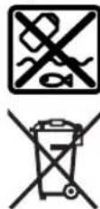
Do not dispose of power tools and batteries/re-chargeable batteries into household waste!
Battery packs/batteries:
Li-ion:
Please observe the notes in the section on transport (see
"Transport", page 28).
French
Robert Bosch Morocco SARL
- Rue Lieutenant Mahmoud Mohamed
20300 Casablanca
Tel.: +212 5 29 31 43 27
E-Mail: sav.outillage@ma.bosch.com
www.bosch-pt.com/serviceaddresses
Transport
www.bosch-pt.com/serviceaddresses
Transport
Calle Robert Bosch No. 405
C.P. 50071 Zona Industrial, Toluca - Estado de Mexico
Tel.: (52) 55 528430-62
Tel.: 8006271286
www.bosch-pt.com/serviceaddresses
Transport
Check the dimensions of the blade
3601M440K0
www.bosch-pt.com/serviceaddresses
92|Chinese
Transport
www.bosch-pt.com/serviceaddresses
Transport
www.bosch-pt.com/serviceaddresses
Transport
118
a 1
m
a
4 1
120


3601 M44 000 3601M440K0 3601M44040
3601M44OB0
3601M44000 3601M440K0 3601M44040
a 1234567890123456789012345678901234567890123456789012345678901234567890123456789012345678901234567890123456789 b wuulwulwulwulwulwulwulwulwulwulwulwulwulwulwulwulwulwulwulwulwulwulwulwulwulwulwulwulwulwulwulwulwulwulwulwulwulwulwulwulwulwulwulwulwulwulwulwulwulwulwul cpanunuynnnn 1.6 d nannnnaeauu (nnnnuanrnuuun) naaonnu
3601M44OB0
124
-173:11000000000000000000000000000000
- 100000000000000000000000000000000000000000000000
muaaunuunnun (uuu) (unwnuunB) uuuuuuuuuuuuuuuuuuuuuuuuuuuuuuuuuuuuuuuuuuuuuuuuuuuuuuuuuuuuuuuuuuuuuuuuuuuuuuuuuuuuuuuuuuuuuuuuuuuuuuuuuuuuuuuuuuuuuuuuuuuuuuuuuuuuuuuuuuuuuuuuuuuuuuuuuuuuuuuuuuuuuuuuuuuuuuuuuuuuuuuuuuuuuuuuuuuuuuuuuUU
-anaunuaa (20) onlunumunuunm mnnnnaaannnnaanana aunna 30 - 14 (14) slotted link uuuu (21) - uunuululucunununuaaunu(20)nun
nunuunnuunnuunnuuunnu 0' uae 45 uuuuuuuuuuuuuuuuuuuuuuuuuuuuuuuuuuuuuuuuuuuuuuuuuuuuuuuuuuuuuuuuuuuuuuuuuuuuuuuuuuuuuuuuuuuuuuuuuuuuuuuuuuuuuuuuuuuuuuuuuuuuuuuuuuuuuuuuuuuuuuuuuuuuuuuuuuuuuuuuuuuuuuuuuuuuuuuuuuuuuuuuuuuuuuuuuuuuuuuuUU
1nwnnnn nn nnnnnae 2nnnne
m0/45°
- 一
- 30
nannnnnau (gnwnnuJ1)
nnuu (3) uunnuuuvnuu (11) uuuuuuuuuuuu (39)
10
JUANNUO (9) JIJIUNN (69)
| 3 601 M44 0BO: | |
| Standard for Wood 216 x 2.0/1.4 x 25.4 mm., 24 mm/min | 2608841163 |
| 3 601 M44 000, 3 601 M44 0K0, 3 601 M44 040: | |
| Standard for Wood 216 x 2.0/1.4 x 30 mm., 48 mm mm/min | 2608837726 |
| Expert for Wood 216 x 1.7/1.2 x 30 mm., 24 mm mm/min | 2608644520 2608644521 |
| 216 x 1.7/1.2 x 30 mm., 48 mm mm/min | |
| laser powder powder powder powder powder powder powder powder powder powder powder powder powder powder powder powder powder powder powder powder powder powder powder powder powder powder powder powder powder powder powder powder powder powder powder powder powder powder powder powder powder powder powder powder powder powder powder powder powder powder powder powder powder powder powder powder powder powder powder powder powder powder powder powder powder powder powder powder powder powder powder powder powder powder powder powder powder powder powder powder powder powder powder powder powder powder powder powder powder powder powder powder powder powder powder powder powder powder powder powderpowder powder powder powder powder powder powder powder powder powder powder powder powder powder powder powder powder powder powder powder powder powder powder powder powder powder powder powder powder powder powder powder powder powder powder powder powder powder powder powder powder powder powder powder powder powder powder powder powder powder powder powder powder powder powder powder powder powder powder powder powder powder powder powder powder powder powder powder powder powder powder powder powder powder powder powder powder powder powder powder powder powder powder powder powder powder powder powder powder powder powder powder powder powder powder powder powder powder powder powder powders | |
| Expert for Aluminium 216 x 2.0/1.4 x 30 mm., 66 mm mm/min | |
| laser powder powder powder powder powder powder powder powder powder powder powder powder powder powder powder powder powder powder powder powder powder powder powder powder powder powder powder powder powder powder powder powder powder powder powder powder powder powder powder powder powder powder powder powder powder powder powder powder powder powder powder powder powder powder powder powder powder powder powder powder powder powder powder powder powder powder powder powder powder powder powder powder powder powder powder powder powder powder powder powder powder powder powder powder powder powder powder powder powderpowder powder powder powder powder powder powder powder powderpowder powder powder powder powder powder powder powder powder powder powder powder powder powder powder powder powder powder powder powder powder powder powder powder powder powder powder powder powder powder powder powder powder powder powder powder powder powder powder powder powder powder powder powder powder powder powder powder powder powder powder powder powder powder powder powder powder powder powder powder powder powder powder powder powder powder powder powder powder powder powder powder powder powder powder powder powder powder powder powder powder powder powder powder powder powder powder powder powder powderpowder powder powder powder powder powder powder powder powder powders | |
| Expert for Laminated Panel 216 x 2.1/1.4 x 30 mm., 66 mm mm/min | 2608644552 |
nwnnnnnaaannnnnnae
In
15
10110
In: +66 2012 8888
wn: +66 2064 5800
www.bosch.co.th
www.bosch-pt.com/serviceaddresses

Personnel safety
Palma Tower 10th Floor
Jalan RA Kartini II-S Kaveling 6
Pondok Pinang, Kebayoran Lama
www.bosch-pt.com/serviceaddresses
Transport
Additional safety warnings
When fitting the saw blade, wear protective gloves. This involves a risk of injury. Do not use HSS steel saw blades. Such saw blades can break easily. Only use saw blades that match the technical characteristics specified in the operating instructions and on the power tool, and that have been tested and marked in accordance with EN 847-1. Do not use the power tool without the riving knife. Replace a damaged riving knife. An imperfect riving knife can cause injury. Keep your workplace clean. Material mixtures are particularly dangerous. Light metal dust can burn or explode. Choose a saw blade suitable for the material you want to work on. Only use saw blades recommended by the manufacturer and suitable for cutting the type of material being processed. You may only work with the saw blade running. Otherwise, there is a risk of kickback when the saw blade becomes jammed in the workpiece. If the battery is damaged or used incorrectly, vapors may escape. The battery can burn or explode. Ensure good ventilation and seek medical attention if you experience discomfort. Vapors can irritate the respiratory tract. Do not disassemble the battery. There is a risk of short circuit. The battery can be damaged by sharp objects such as nails or screwdrivers or by external impacts. This can lead to internal short circuits and cause the battery to burn, smoke, explode, or overheat. Only use the battery in products from the manufacturer. Only in this way will the battery be protected against overload.
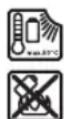
Protect the battery from heat, for example, from prolonged exposure to direct sunlight, fire, dirt, water, and moisture. There is a risk of explosion and short circuit.
Symbols
The following symbols may convey meaning about how to use your cordless power tool.
Please take note of the symbols and their meanings. Understanding the symbols will help you use the machine better and more safely.
Insert the chuck (9) into the Depot (69)
Insert the auxiliary handle (2) into the Depot (7)
Push the auxiliary handle (43) into the groove on the rear of the handle (5) and tighten with the bolt at the side
Carrying the Power Tool
Before carrying out any work on the machine (e.g., maintenance, tool change, etc.) as well as when transporting or storing, remove the battery from the power tool. There is a risk of injury if the On/Off switch is accidentally activated. Before transporting the power tool, carry out the following steps: - Move the power tool to the transport position (see "Transport Position", page 159). - If possible, place the saw blades that are not being used in a closed container for transport.
If possible, place the saw blades that are not being used in a closed container for transport.
Push the saw blade guard fully back (6) and press the locking lever (13) down to secure it.
- Use the handles to lift or transport (29). When transporting the power tool, only use the transport devices and never use the protective devices to carry or lift.
www.bosch-pt.com/serviceaddresses
Transport
Batteries with Li-Ion are subject to the regulations for Dangerous Goods. The user can transport the battery by road without any further requirements.
When transported by third parties (e.g., by air freight or forwarding agent), special requirements for packaging and labeling must be observed. Consult the dangerous goods specialist when preparing the shipment.
When storing the battery pack, keep it away from moisture to prevent damage. Cover the contact points with tape or seal them, and package the battery pack so that it cannot move around inside the packaging. Additionally, please comply with any additional detailed regulations that may be imposed by your country.
164 | Vietnamese
Disposal

Power tools, batteries, accessories, and packaging should be recycled in accordance with environmental regulations.
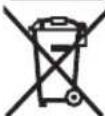
Do not dispose of power tools and batteries in household waste!
Batteries/rechargeable batteries:
Li-Ion:
Follow the instructions in the transport section (see "Transport," page 163).
__SUPPIMER__
The device is designed to be used in accordance with the instructions provided in this manual.
Please read the instructions carefully before use.
Keep the device away from water and moisture.
Do not expose the device to extreme temperatures.
If the device is damaged, do not use it and contact customer support.
__SUPPIMER__
49
aJlglaiolwU (49) wI dGol -
(50) UJgU Jgoo CwE gU S wIg (9)
auiu uuaagglmuai
aJoljLgliojolgolwJgolw
.
(4) (25)
38) uJ. aL
.1SsoJgOJou . - aJll aioi
1gol auiu 5s L gaiu1 pLs
LgaiIoo ggejoll
- Jooai jka
aJgggw oJU
JjI Jn oJwJ/JeJabJw j
.1juii aia 0o ojuu o jai g i juiil g
. lo la
. lo la
.
(a ojgl jbl) (33) aJjAaW e1-
Jwll 47
Iaill Iaill g, aai lao 10
46(1101 8jai
.1jwll aabg oJluw g Ukuw Uji -
(Ajgall jbl) JuaiaIoo
10 6) 1111 23
JUbLolai JI (13) 1uO - JuaJI OcIg
(6)jwaiolosclsioaog 1gajllglal
jgJUwI (13) uU Juaa bdu - UuJuaia I dlaI a
aJgsslllallllglj
aaglg
yI yI yI yI yI yI yI yI yI yI yI yI yI yI yI yI yI yI yI yI yI yI yI yI yI yI yI yI yI yI yI yI yI yI yI yI yI yI yI yI yI yI yI yI yI yI yI yI yI yI yI
(jlaij j) a gssllgj (Bgjgl)
gai yasal allal lglj bdo kso 45g0 u2g
176
Jc 0gagall (35) UoIaI I gSj uI aI .Gogo go loa aggo (36) laalgljg eluall
山
(G1jgJJIj)
(16)labg uawu liao lc beol uuwu - .Ucl dag uil
(G2gJgJlJI)
U1(16)abg uusuui elao Uc bai
jbl) a jaoJI Jn JlaaWJI Jo aJoo (G3 oJgJU
gio elSao a jaoaJmu JuswJoo ayLsU 16 LbIg Jswu Iao oJau
g 16. g
JdI 1
aolemuUko
XgabaaLac gJl JgddSgJg 1g jg dgsaJgJiaaiol oaw mdoj .abJg jqll no jg jgjll JajuJgKJgJgJgJgJgJgJgJgJgJgJgJgJgJgJgJgJgJgJgJgJgJgJgJgJgJgJgJgJgJgJgJgJgJgJgJgJgJgJgJgJgJgJgJgJgJgJgJgJgJgJg
aJgSj 0sJg 0g - oJg 0sJg 0sJg 0sJg 0sJg 0sJg 0sJg 0sJg 0sJg 0sJg 0sJg 0sJg 0sJg 0sJg 0sJg 0sJg 0sJg 0sJg 0sJg 0sJg 0sJg 0
J30) jJI J (54) 1
178
25) 1000000000000000000000000000000000000000000000000000000000000000000000
(2) [5g]
JgU 5
! (5jglg 43)
aJyj≤JJ oJdJI Jaa
Jl Jd auiyjSJJ oSJJ eji 1
gI gai iie Ig (..g 1sJl J Ic baii sic gjy aol jia liu. qiu jsi gao u Kuy labygl uui aliao
0sJ1 Jai jia auiu 1gbi (auii
jai)jaiIgglcduuJgSJIosJIbui- (175 aaiJl,“jaiIg
0sJU 1u2gulglgulg
Lg LlAsiw pi y uuiuaiu uow g
buai
-wwJl aawLsw
wJlI aWJw cJgUg JluuI JwI
62(paiwjuiai
10(
-1030.
62) g(61) UgUaLbJp≤
jgl) juiiJ 0dLg 1
: www.bosch-pt.com/serviceaddresses
JaiI gilaasajgulilgipgsj Jai paoi pssuaaagaa. jgal bgw ayuauuuguui ggl uallp
jull:10) jI jI jI jI qI JUJU JUJU UJU UJU UJU UJU UJU UJU UJU UJU UJU UJU UJU UJU UJU UJU UJU UJU UJU UJU UJU UJU UJU UJU UJU UJU UJU UJU UJU UJU UJU UJU UJU UJU UJU U
auijseJoo yalil
auiy 000000000000000000000000000000000000000000000000000000000000000
/ajjJg aJUaJG 1 JI JI JI JI JI JI JI JI JI
:UJbJI/psJJI
gull Uglj 1
-1uioiaol oscIg u
JU 13(jo JwJg
-(20 19
4aJai sic lai
__SUPPIMER__
osch-pt.com
Therefore, m - 1 ≠ 0;
0601B22700 GTA560Joaia
0601B12000 GTA 60W JosJoo
1600A01ZE5
:3601M44OBU
Standard for Wood
2608841163 25,4x2,0/1,4x216
24
3601M440KO,3601M44000
:3601M44040
Standard for Wood
2608837726 48.030x2,0/1,4x216
Expert for Wood
2608644520 24,30x1,7/1,2x216
2608644521 48,30x1,7/1,2x216
180|
__SUPPIMER__
(1 + u)/8 = u/8
150g 10g 10g 10g 10g 10g 10g 10g 10g 10g 10g 10g 10g 10g 10g 10g 10g 10g 10g 10g 10g 10g 10g 10g 10g 10g 2
4LwJd ω μ a g l j
150j
__SUPPIMER__

3601M44000 3601M440K0 3601M44040
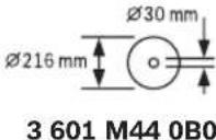
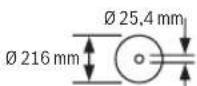
Dimensions: 216 mm
The cable entry is 1.7 mm thick, and the cable entry is 1.5 mm thick. The cable entry is made of rubber, and the cable entry is made of plastic.
1.6 mm diameter
3601M44000 3601M44OK0 3601M44040
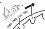
Cable entry (cable entry) for 10 mm cable (cable entry).
Dimensions: 216 mm
The cable entry is 2.3 mm thick, and the cable entry is 2.1 mm thick. The cable entry is made of rubber, and the cable entry is made of plastic.
2.2 mm diameter
3601M44OB0
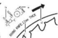
Cable entry (cable entry) for 10 mm cable (cable entry).
1.6 mm diameter, with a sealing ring and a locking nut.
3601M44000 3601M44OK0 3601M44040
A
J
i 1
.
Lgaw Lg
g j 1 g j
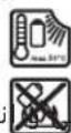
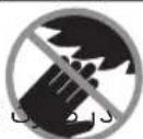

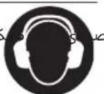
| (5 mm) | (10) |
| (11) | |
| (12) | |
| (13) | |
| (14) | |
| (15) | |
| (16) | |
| (17) | |
| (18) | |
| (19) | |
| (20) | |
| (21) | |
| (22) | |
| (23) | |
| (24) | |
| (25) | |
| (26) | |
| (27) | |
| (a) | (28) |
| (b) | (29) |
| (c) | (30) |
| (d) | (31) |
| (e) | (32) |
| (f) | (33) |
| (g) | (34) |
| (h) | (35) |
| (i) | (36) |
| (j) | (37) |
| (k) | (38) |
| (l) | (39) |
| (m) | (40) |
| (n) | (41) |
| (o) | (42) |
| (p) | (43) |
| (q) | (44) |
| (r) | (45) |
| (s) | (46) |
| (t) | (47) |
| (u) | (48) |
| (v) | (49) |
| (w) | (50) |
| (x) | (51) |
| (y) | (52) |
(3) 46.15 mm
__SUPPIMER__
Remove
Remove
Remove
Remove
Remove
Remove
Remove
Remove
Remove
Remove
Remove
Remove
Remove
Remove
Remove
Figure 9. Tool according to EN 847-1. Dimensions in mm
The tool must be used only for the intended purpose.
Safety instructions
Warning
[5g] Read the operating instructions
Before use, check the tool for damage.
(Figure) 8. Dimensions in mm
J5 J 59] o ogo Bosch du sEgj jgi
jL jo Bosch wlo) GTA 5
gai gui jui jui jiu o l qij elajl aS (59)j pao g jiaowu yjulj (s) . jluo paolj 1 s dioj dig
labl 1sIJgws
gJjL joI abI j0saw
aJlbojUcLjcJwli
cuii i jaij 150 jaij g g lSi
__SUPPIMER__
__SUPPIMER__
| aòbā lαòjì lαiùyù [jǎo] jL | lǜyù lǜyù yī gǔ lǚ |
| 70 | 0° |
| 50 | 45° |
a 10
| Jr | Olg | L | Sj | Pj | Gg | Ij | (5) | Sj | go | L | Sj | g | - |
| . | . | . | . | . | . | . | . | . | . | . | . | . | . |
| Jr | (3) | L | Sj | Sg | J | Sj | J | Sj | J | J | Sj | d | - |
| . | . | . | . | . | . | . | . | . | . | . | . | . | J |
| d | S | S | S | S | J | J | J | J | J | J | J | J | J |
| 3 | -6 | mm | Sg | d | (26) | J | J | d | d | J | J | J | J |
| . | . | . | . | . | . | . | . | . | . | . | . | . | J |
| . | . | . | . | . | . | . | . | . | . | . | . | . | J |
| . | . | . | . | . | . | . | . | . | . | . | . | . | J |
www.bosch-pt.com/serviceaddresses
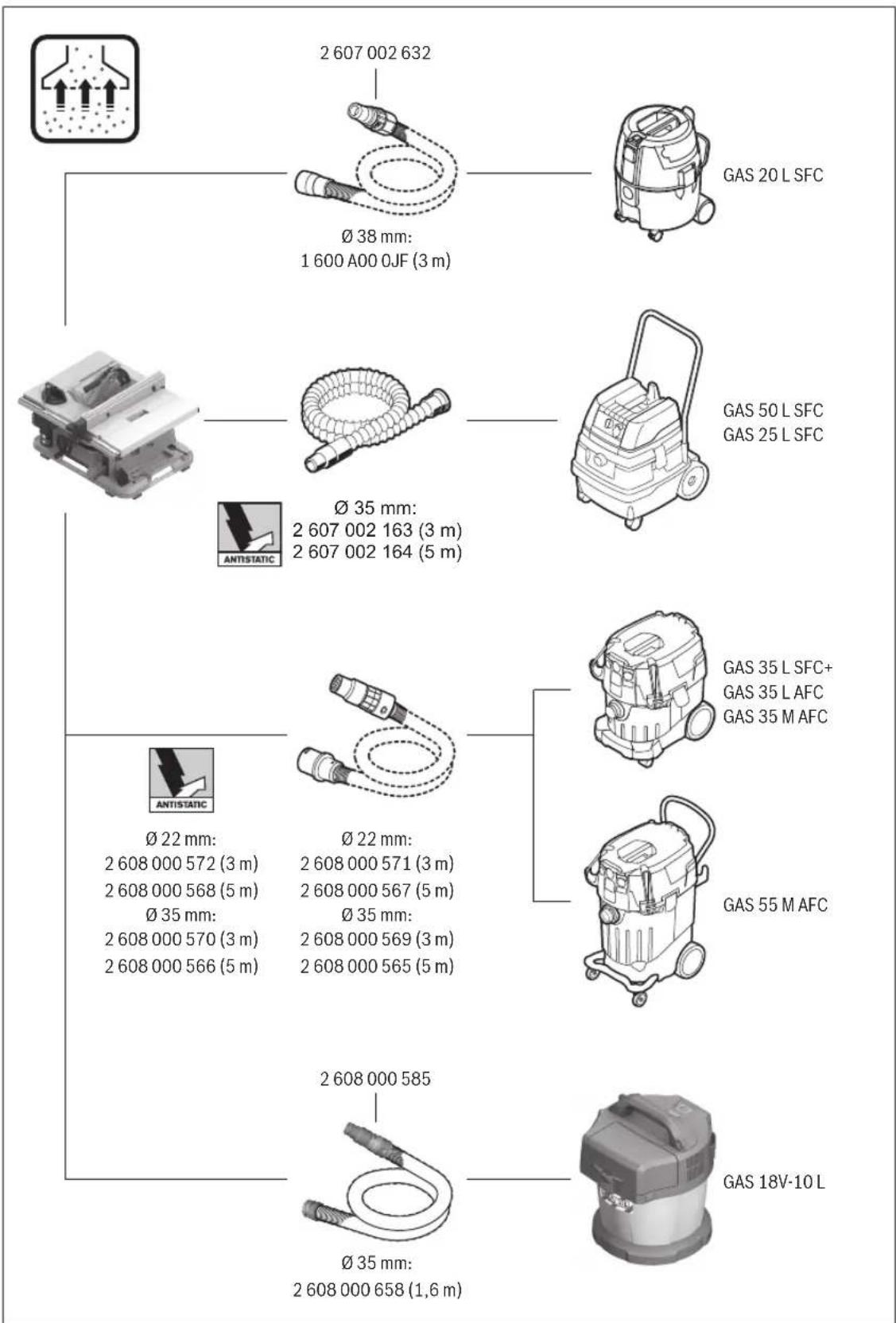
Licenses
Copyright © 2009-2020 ARM LIMITED
All rights reserved.
Redistribution and use in source and binary forms, with or without modification, are permitted provided that the following conditions are met:
- Redistributions of source code must retain the above copyright notice, this list of conditions and the following disclaimer.
- Redistributions in binary form must reproduce the above copyright notice, this list of conditions and the following disclaimer in the documentation and/or other materials provided with the distribution.
- Neither the name of ARM nor the names of its contributors may be used to endorse or promote products derived from this software without specific prior written permission.
THIS SOFTWARE IS PROVIDED BY THE COPYRIGHT HOLDERS AND CONTRIBUTORS "AS IS" AND ANY EXPRESS OR IMPLIED WARRANTIES, INCLUDING, BUT NOT LIMITED TO, THE IMPLIED WARRANTIES OF MERCHANTABILITY AND FITNESS FOR A PARTICULAR PURPOSE ARE DISCLAIMED. IN NO EVENT SHALL THE COPYRIGHT OWNER OR CONTRIBUTORS BE LIABLE FOR ANY DIRECT, INDIRECT, INCIDENTAL, SPECIAL, EXEMPLARY, OR CONSEQUENTIAL DAMAGES (INCLUDING, BUT NOT LIMITED TO, PROCUREMENT OF SUBSTITUTE GOODS OR SERVICES; LOSS OF USE, DATA, OR PROFITS; OR BUSINESS INTERRUPTION) HOWEVER CAUSED AND ON ANY THEORY OF LIABILITY, WHETHER IN CONTRACT, STRICT LIABILITY, OR TORT (INCLUDING NEGLIGENCE OR OTHERWISE) ARISING IN ANY WAY OUT OF THE USE OF THIS SOFTWARE, EVEN IF ADVISED OF THE POSSIBILITY OF SUCH DAMAGE.
Apache License
Copyright © 2009-2019 Arm Limited. All rights reserved.
Version 2.0, January 2004
http://www.apache.org/licenses/
TERMS AND CONDITIONS FOR USE, REPRODUCTION, AND DISTRIBUTION
1. Definitions.
"License" shall mean the terms and conditions for use, reproduction, and distribution as defined by Sections 1 through 9 of this document.
"Licensor" shall mean the copyright owner or entity authorized by the copyright owner that is granting the License.
"Legal Entity" shall mean the union of the acting entity and all other entities that control, are controlled by, or are under common control with that entity. For the purposes of this definition, "control" means (i) the power, direct or indirect, to cause the direction or management of such entity, whether by contract or otherwise, or (ii) ownership of fifty percent (50%) or more of the outstanding shares, or (iii) beneficial ownership of such entity.
"You" (or "Your") shall mean an individual or Legal Entity exercising permissions granted by this License.
"Source" form shall mean the preferred form for making modifications, including but not limited to software source code, documentation source, and configuration files.
"Object" form shall mean any form resulting from mechanical transformation or translation of a Source form, including but not limited to compiled object code, generated documentation, and conversions to other media types.
"Work" shall mean the work of authorship, whether in Source or Object form, made available under the License, as indicated by a copyright notice that is included in or attached to the work (an example is provided in the Appendix below).
"Derivative Works" shall mean any work, whether in Source or Object form, that is based on (or derived from) the Work and for which the editorial revisions, annotations, elaborations, or other modifications represent, as a whole, an original work of authorship. For the purposes of this License, Derivative Works shall not include works that remain separable from, or merely link (or bind by name) to the interfaces of, the Work and Derivative Works thereof.
"Contribution" shall mean any work of authorship, including the original version of the Work and any modifications or additions to that Work or Derivative Works thereof, that is intentionally submitted to Licensor for inclusion in the Work by the copyright owner or by an individual or Legal Entity authorized to submit on behalf of the copyright owner. For the purposes of this definition, "submitted" means any form of electronic, verbal, or written communication sent to the Licensor or its representatives, including but not limited to communication on electronic mailing lists, source code control systems, and issue tracking systems that are managed by, or on behalf of, the Licensor for the purpose of discussing and improving the Work, but excluding communication that is conspicuously marked or otherwise designated in writing by the copyright owner as "Not a Contribution."
"Contributor" shall mean Licensor and any individual or Legal Entity on behalf of whom a Contribution has been received by Licensor and subsequently incorporated within the Work.
- Grant of Copyright License. Subject to the terms and conditions of this License, each Contributor hereby grants to You a perpetual, worldwide, non-exclusive, no-charge, royalty-free, irrevocable copyright license to reproduce, prepare Derivative Works of, publicly display, publicly perform, sublicense, and distribute the Work and such Derivative Works in Source or Object form.
- Grant of Patent License. Subject to the terms and conditions of this License, each Contributor hereby grants to You a perpetual, worldwide, non-exclusive, no-charge, royalty-free, irrevocable (except as stated in this section) patent license to make, have made, use, offer to sell, sell, import, and otherwise transfer the Work, where such license applies only to those patent claims licensable by such Contributor that are necessarily infringed by their Contribution(s) alone or by combination of their Contribution(s) with the Work to which such Contribution(s) was submitted. If You institute patent litigation against any entity (including a cross-claim or counterclaim in a lawsuit) alleging that the Work or a Contribution incorporated within the Work constitutes direct or contributory patent infringement, then any patent licenses granted to You under this License for that Work shall terminate as of the date such litigation is filed.
- Redistribution. You may reproduce and distribute copies of the Work or Derivative Works thereof in any medium, with or without modifications, and in Source or Object form, provided that You meet the following conditions:
- You must give any other recipients of the Work or Derivative Works a copy of this License; and
- You must cause any modified files to carry prominent notices stating that You changed the files; and You must retain, in the Source form of any Derivative Works that You distribute, all copyright, patent, trademark, and attribution notices from the Source form of the Work, excluding those notices that do not pertain to any part of the Derivative Works; and If the Work includes a "NOTICE" text file as part of its distribution, then any Derivative Works that You distribute must include a readable copy of the attribution notices contained within such NOTICE file, excluding those notices that do not pertain to any part of the Derivative Works, in at least one of the following places: within a NOTICE text file distributed as part of the Derivative Works; within the Source form or documentation, if provided along with the Derivative Works; or, within a display generated by the Derivative Works, if and wherever such third-party notices normally appear. The contents of the NOTICE file are for informational purposes only and do not modify the License.
You may add Your own attribution notices within Derivative Works that You distribute, alongside or as an addendum to the NOTICE text from the Work, provided that such additional attribution notices cannot be construed as modifying the License. You may add Your own copyright statement to Your modifications and may provide additional or different license terms and conditions for use, reproduction, or distribution of Your modifications, or for any such Derivative Works as a whole, provided Your use, reproduction, and distribution of the Work otherwise complies with the conditions stated in this License.
- Submission of Contributions. Unless You explicitly state otherwise, any Contribution intentionally submitted for inclusion in the Work by You to the Licensee shall be under the terms and conditions of this License, without any additional terms or conditions. Notwithstanding the above, nothing herein shall supersede or modify the terms of any separate license agreement you may have executed with Licensee regarding such Contributions.
- Trademarks. This License does not grant permission to use the trade names, trademarks, service marks, or product names of the Licensor, except as required for reasonable and customary use in describing the origin of the Work and reproducing the content of the NOTICE file.
- Disclaimer of Warranty. Unless required by applicable law or agreed to in writing, Licensee provides the Work (and each Contributor provides its Contributions) on an "AS IS" BASIS, WITHOUT WARRANTY OR CONDITIONS OF ANY KIND, either express or implied, including, without limitation, any warranties or conditions of TITLE, NON-INFRINGEMENT, MERCHANTABILITY, or FITNESS FOR A PARTICULAR PURPOSE. You are solely responsible for determining the appropriateness of using or redistributing the Work and assume any risks associated with Your exercise of permissions under this License.
- Limitation of Liability. In no event and under no legal theory, whether in tort (including negligence), contract, or otherwise, unless required by applicable law (such as deliberate and grossly negligent acts) or agreed to in writing, shall any Contributor be liable to You for damages, including any direct, indirect, special, incidental, or consequential damages of any character arising as a result of this License or out of the use or inability to use the Work (including but not limited to damages for loss of goodwill, work stoppage, computer failure or malfunction, or any and all other commercial damages or losses), even if such Contributor has been advised of the possibility of such damages.
- Accepting Warranty or Additional Liability. While redistributing the Work or Derivative Works thereof, You may choose to offer, and charge a fee for, acceptance of support, warranty, indemnity, or other liability obligations and/or rights consistent with this License. However, in accepting such obligations, You may act only on Your own behalf and on Your sole responsibility, not on behalf of any other Contributor, and only if You agree to indemnify, defend, and hold each Contributor harmless for any liability incurred by, or claims asserted against, such Contributor by reason of your accepting any such warranty or additional liability.
200
END OF TERMS AND CONDITIONS
Copyright © 2012-2019 STMicroelectronics
All rights reserved.
Redistribution and use in source and binary forms, with or without modification, are permitted provided that the following conditions are met:
- Redistributions of source code must retain the above copyright notice, this list of conditions and the following disclaimer.
- Redistributions in binary form must reproduce the above copyright notice, this list of conditions and the following disclaimer in the documentation and/or other materials provided with the distribution. Neither the name of STMicroelectronics nor the names of its contributors may be used to endorse or promote products derived from this software without specific prior written permission.
THIS SOFTWARE IS PROVIDED BY THE COPYRIGHT HOLDERS AND CONTRIBUTORS "AS IS" AND ANY EXPRESS OR IMPLIED WARRANTY, INCLUDING, BUT NOT LIMITED TO, THE IMPLIED WARRANTIES OF MERCHANTABILITY AND FITNESS FOR A PARTICULAR PURPOSE ARE DISCLAIMED. IN NO EVENT SHALL THE COPYRIGHT OWNER OR CONTRIBUTORS BE LIABLE FOR ANY DIRECT, INDIRECT, INCIDENTAL, SPECIAL, EXEMPLARY, OR CONSEQUENTIAL DAMAGES (INCLUDING, BUT NOT LIMITED TO, PROCUREMENT OF SUBSTITUTE GOODS OR SERVICES; LOSS OF USE, DATA, OR PROFITS; OR BUSINESS INTERRUPTION) HOWEVER CAUSED AND ON ANY THEORY OF LIABILITY, WHETHER IN CONTRACT, STRICT LIABILITY, OR TORT (INCLUDING NEGLIGENCE OR OTHERWISE) ARISING IN ANY WAY OUT OF THE USE OF THIS SOFTWARE, EVEN IF ADVISED OF THE POSSIBILITY OF SUCH DAMAGE.
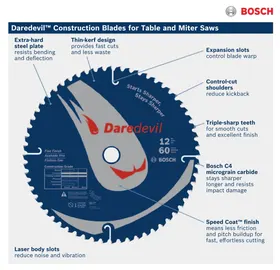


- GENERAL POWER TOOL SAFETY WARNINGS
- WARNING
- KEEP WORK AREA CLEAN AND WELL LIT. CLUTTERED OR DARK AREAS INVITE ACCIDENTS
- POWER TOOL PLUGS MUST MATCH THE OUTLET. NEVER MODIFY THE PLUG IN ANY WAY. DO NOT USE ANY ADAPTER PLUGS WITH EARTHED (GROUNDED) POWER TOOLS. UNMODIFIED PLUGS AND MATCHING OUTLETS WILL REDUCE RISK OF ELECTRIC SHOCK. AVOID BODY CONTACT WITH EARTHED OR GROUNDED SURFACES, SUCH AS PIPES, RADIATORS, RANGES AND REFRIGERATORS. THERE IS AN INCREASED RISK OF ELECTRIC SHOCK IF YOUR BODY IS EARTHED OR GROUNDED. DO NOT EXPOSE POWER TOOLS TO RAIN OR WET CONDITIONS. WATER ENTERING A POWER TOOL WILL INCREASE THE RISK OF ELECTRIC SHOCK. DO NOT ABUSE THE CORD. NEVER USE THE CORD FOR CARRYING, PULLING OR UNPLUGGING THE POWER TOOL. KEEP CORD AWAY FROM HEAT, OIL, SHARP EDGES OR MOVING PARTS. DAMAGED OR ENTANGLED CORDS INCREASE THE RISK OF ELECTRIC SHOCK. WHEN OPERATING A POWER TOOL OUTDOORS, USE AN EXTENSION CORD SUITABLE FOR OUTDOOR USE. USE OF A CORD SUITABLE FOR OUTDOOR USE REDUCES THE RISK OF ELECTRIC SHOCK. IF OPERATING A POWER TOOL IN A DAMP LOCATION IS UNAVOIDABLE, USE A RESIDUAL CURRENT DEVICE (RCD) PROTECTED SUPPLY. USE OF AN RCD REDUCES THE RISK OF ELECTRIC SHOCK
- STAY ALERT, WATCH WHAT YOU ARE DOING AND USE COMMON SENSE WHEN OPERATING A POWER TOOL. DO NOT USE A POWER TOOL WHILE YOU ARE TIRED OR UNDER THE INFLUENCE OF DRUGS, ALCOHOL OR MEDICATION. A MOMENT OF INATTENTION WHILE OPERATING POWER TOOLS MAY RESULT IN SERIOUS PERSONAL INJURY
- POWER TOOL USE AND CARE
- BATTERY TOOL USE AND CARE
- SERVICE
- SAFETY INSTRUCTIONS FOR TABLE SAWS
- GUARDING RELATED WARNINGS
- CUTTING PROCEDURES WARNINGS
- KICKBACK CAUSES AND RELATED WARNINGS
- TABLE SAW OPERATING PROCEDURE WARNINGS
- ADDITIONAL SAFETY WARNINGS
- SYMBOLS
- SYMBOLS AND THEIR MEANING
- M440B
- M
- M440K
- LEFT-HAND SIDE
- RIGHT-HAND SIDE
- PRODUCT DESCRIPTION AND SPECIFICATIONS
- READ ALL THE SAFETY AND GENERAL INSTRUCTIONS
- INTENDED USE
- PRODUCT FEATURES
- TECHNICAL DATA
- TABLE SAW GTS 18V-216 GTS 18V
- NOISE INFORMATION
- WEAR HEARING PROTECTION
- ASSEMBLY
- ITEMS INCLUDED
- EXTRA TOOLS REQUIRED (NOT INCLUDED IN THE DELIVERY)
- FITTING INDIVIDUAL COMPONENTS
- POSITIONING THE RIVING KNIFE (SEE FIGURES B1-B2)
- ENGLISH
- FITTING THE TABLE INSERT (SEE FIGURE C)
- FITTING THE PROTECTIVE COVER (SEE FIGURES D1-D2)
- FITTING THE PARALLEL GUIDE (SEE FIGURE E)
- FITTING THE ADDITIONAL PARALLEL GUIDE (SEE FIGURE F)
- FITTING THE ANGLE GUIDE (SEE FIGURE G)
- BATTERY CHARGING
- REMOVING THE BATTERY
- BATTERY CHARGE INDICATOR
- LEDS CAPACITY
- STATIONARY OR FLEXIBLE MOUNTING
- MOUNTING ON A WORK SURFACE (SEE FIGURE H)
- MOUNTING ON A BOSCH SAW STAND (SEE FIGURE I)
- DUST/CHIP EXTRACTION
- CLEANING THE LOWER SAW BLADE COVER (SEE FIGURE J)
- EXTERNAL DUST EXTRACTION (SEE FIGURE K)
- CHANGING THE SAW BLADE (SEE FIGURES I1-I4)
- REMOVING THE SAW BLADE
- FITTING THE SAW BLADE
- OPERATION
- TRANSPORT POSITION AND WORK POSITION OF THE SAW BLADE
- TRANSPORT POSITION
- WORK POSITION
- EXTENDING THE SAW TABLE
- SAW TABLE EXPANSION (SEE FIGURE A)
- SETTING METRE AND BEVEL ANGLES
- SETTING BEVEL ANGLES (SAW BLADE) (SEE FIGURE B)
- SETTING LITRE ANGLES (ANGLE GUIDE) (SEE FIGURE C)
- ADJUSTING THE PARALLEL GUIDE
- ADJUSTING THE PARALLEL GUIDE WHEN THE SAW TABLE IS NOT PULLED OUT
- ADJUSTING THE PARALLEL GUIDE WHEN THE SAW TABLE IS PULLED OUT (SEE FIGURE D)
- ADJUSTING THE ADDITIONAL PARALLEL GUIDE (SEE FIGURE E)
- ADJUSTING THE RIVING KNIFE
- ADJUSTING THE RIVING KNIFE HEIGHT (SEE FIGURE F)
- START-UP
- SWITCHING ON (SEE FIGURE G1)
- SWITCHING OFF (SEE FIGURE G2)
- PROTECTION AGAINST UNAUTHORISED USE (SEE FIGURE G3)
- PRACTICAL ADVICE
- GENERAL SAWING INSTRUCTIONS
- POSITION OF THE OPERATOR (SEE FIGURE H)
- SAWING
- MAKING STRAIGHT CUTS
- SAWING A BEVEL ANGLE
- SAWING MITRE ANGLES (SEE FIGURE 1)
- CHECKING AND ADJUSTING THE BASIC SETTINGS
- ADJUSTING THE STOPS FOR A STANDARD BEVEL ANGLE 0° / 45°
- CHECKING (SEE FIGURE J1)
- SETTING (SEE FIGURE J2)
- PARALLELISM OF THE SAW BLADE WITH THE GUIDE GROOVES OF THE ANGLE GUIDE (SEE FIGURE K)
- CHECKING
- SETTING
- ADJUSTING THE SAW TABLE SPACING INDICATOR (SEE FIGURE L)
- ADJUSTING THE PARALLELISM OF THE PARALLEL GUIDE (SEE FIGURE M)
- ADJUSTING THE CLAMPING FORCE OF THE PARALLEL GUIDE
- SETTING THE SCALE DISPLAY OF THE PARALLEL GUIDE (SEE FIGURE M)
- ADJUSTING THE LEVEL OF THE TABLE INSERT (SEE FIGURE N)
- STORAGE AND TRANSPORT
- STORING TOOL ELEMENTS (SEE FIGURES 01 - 02)
- TOOL ELEMENT STORAGE COMPARTMENT
- TRANSPORTING THE POWER TOOL
- MAINTENANCE AND SERVICE
- MAINTENANCE AND CLEANING
- CLEANING
- NOISE REDUCTION MEASURES
- AFTER-SALES SERVICE AND APPLICATION SERVICE
- MALAYSIA
- TRANSPORT
- DISPOSAL
- BATTERY PACKS/BATTERIES
- LI-ION
- FRENCH
- CHINESE
- A
- M0/45°
- NANNNNNAU (GNWNNUJ1)
- NWNNNNNAAANNNNNNAE
- IN
- PERSONNEL SAFETY
- CARRYING THE POWER TOOL
- BATTERIES/RECHARGEABLE BATTERIES
- AJGSSLLLALLLLGLJ
- 山
- JDI
- (5JGLG 43)
- AUIJSEJOO YALIL
- SUPPIMER
- LICENSES
- COPYRIGHT © 2009-2020 ARM LIMITED
- APACHE LICENSE
- DEFINITIONS
- COPYRIGHT © 2012-2019 STMICROELECTRONICS
Brand : BOSCH
Model : GTS 18V216 Professional
Category : Saw