
LSIA127 - Washing machine SMEG - Free user manual and instructions
Find the device manual for free LSIA127 SMEG in PDF.
User questions about LSIA127 SMEG
0 question about this device. Answer the ones you know or ask your own.
Ask a new question about this device
Download the instructions for your Washing machine in PDF format for free! Find your manual LSIA127 - SMEG and take your electronic device back in hand. On this page are published all the documents necessary for the use of your device. LSIA127 by SMEG.
USER MANUAL LSIA127 SMEG
text_image
Diagram showing a device with labeled component 'C' and directional arrow, likely illustrating a mechanical or electrical component.Attention!
natural_image
Line drawing of a washing machine and its mechanical lever mechanism (no text or symbols)text_image
Diagram illustrating washing machine operation with labeled dimensions and warning symbolsnatural_image
Illustration of a washing machine with a close-up inset showing mechanical components (no text or symbols)natural_image
Diagram of a faucet with a valve and tap, mounted on a wall (no text or symbols)2.4 VIDANGE
natural_image
Line drawing of a mechanical linkage or rope system (no text or symbols)text_image
8.8:8.8 Max Kg START STOP Offtext_image
Technical diagram of a mechanical assembly with numbered components and directional arrows indicating motion or movement.natural_image
Diagram of a device with a central component and directional arrow, no visible text or symbolstext_image
Control panel interface with icons for temperature, humidity, and operation buttons including 'Start STOP' and 'Max Kg'6. NETTOYAGE ET ENTRETIEN
natural_image
Illustration of a hand placing a dark circular object into a ring (no text or symbols)6.4 NETTOYAGE DE LA POMPE DE VIDANGE
natural_image
Technical line drawing of a mechanical device with mounting holes and a magnified inset showing a folded corner detail (no text or symbols)text_image
Diagram showing a container with a curved arrow indicating direction, alongside an inset diagram illustrating a cutting tool tip.text_image
Technical diagram showing labeled components A, B, and C with a mechanical assembly or device setup
text_image
Technical diagram showing labeled components A, B, C, D, E with directional arrows indicating motion or movementnatural_image
Technical line drawing of a mechanical assembly with labeled component A (no text or symbols beyond labels)6.6 NETTOYAGE DU FILTRE D'ARRIVÉE D'EAU
natural_image
Line drawing of a faucet with a valve and tap, mounted on a wall (no text or symbols)6.7 NETTOYAGE PERIODIQUE
| Programs | Temp. (°C) | Max. Spin (rpm) | Max. washing load (kg) | Max. drying load (kg) | Detergent drawer compartments | Options | Wash program description | ||||||||||||
| Prewash | Wash | Conditioner | Prewash | Intensive | Easy Iron | Extra rinse | Rapid | Drying after wash if selected | |||||||||||
| Cotton and colours | [IMAGE] | Definite colours with light dirt | 20" | Max | 7 | 4 | √ | √ | √ | √ | √ | √ | √ | √ | Normal | Core wash or 26 °C, rinses and final spin at the selected speed | |||
| Definite colours with normal dirt | 40" Max 7 4 | √ | √ | √ | √ | √ | √ | √ | √ | Normal | Wash at 40°C, rinses and final spin at the selected speed | ||||||||
| Normally setd cotton laundry declared washcode at 60°C or 40°C together | Eco 40-60 Max 7 | 4 | √ | √ | √ | √ | - | √ | √ | √ | Normal | Wash, rinses and final spin at the selected speed | |||||||
| Tough colours with normal dirt | 60" Max 7 4 | √ | √ | √ | √ | √ | √ | √ | √ | Normal | Wash at 80°C, rinses and final spin at the selected speed | ||||||||
| Tough colours with heavy dirt | 90" Max 7 4 | √ | √ | √ | √ | √ | √ | √ | √ | Normal | Wash at 90°C, rinses and final spin at the selected speed | ||||||||
| Wool | [IMAGE] | Hand wash | 800 | 2 | - | - | √ | √ | - | - | - | - | - | - | - | Core wash, rinses and final spin at the selected speed | |||
| Delicate | [IMAGE] | Items with light dirt | 30" | 600 | 2 | - | - | √ | √ | - | - | - | - | - | - | - | Wash at 30°C, rinses and final spin at the selected speed | ||
| Rinse and spin | [IMAGE]+ [IMAGE] | - | Max 7 | - | - | √ | - | - | √ | - | √ | - | - | Rinse and pump-out only, or pump-out and final spin at the selected speed | |||||
| Pump-out and spin | [IMAGE]+ [IMAGE] | - | Max 7 | - | - | - | - | - | √ | - | √ | - | - | Pump-out only, or pump-out and final spin at the selected speed | |||||
| Synthetics | [IMAGE] | Items with light dirt | 30" | 1000 | 3.5 | 3.5 | √ | √ | √ | √ | √ | - | √ | √ | Delicate | Wash at 30°C, rinses and final spin at the selected speed | |||
| Items with normal dirt | 40" | 1000 | 3.5 | 3.5 | √ | √ | √ | √ | √ | - | √ | √ | Delicate | Wash at 40°C, rinses and final spin at the selected speed | |||||
| Mixed | [IMAGE] | Cotton and synthetics with light dirt | 30" Max 3 2 | √ | √ | √ | √ | √ | √ | √ | √ | Delicate | Wash at 30°C, rinses and final spin at the selected speed | ||||||
| Rapid | [IMAGE] | Light cotton or delicate fanice for refreshing | 30" | 800 | 2 | - | - | √ | √ | - | - | - | - | - | - | - | Wash at 30°C, rinses and final spin at the selected speed | ||
| Drying | [IMAGE] | Delicate | 60" Max | - | 3 | - | - | - | - | - | - | - | - | - | - | Delicate drying for synthetic and delicate items | |||
| Normal | 90" Max | - | 4 | - | - | - | - | - | - | - | - | - | - | Normal drying for cotton items | |||||
| Clean | - | - | - | - | - | - | - | - | - | - | - | - | - | - | Drying circuit cleaning cycle | ||||

: Options which cannot be selected simultaneously
PROGRAMM-LEITFADEN
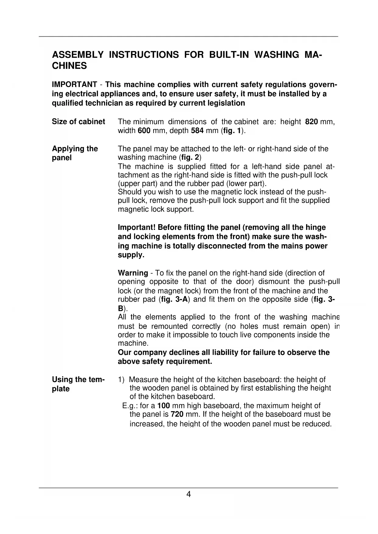
ASSEMBLY INSTRUCTIONS FOR BUILT-IN WASHING MA- CHINES
IMPORTANT - This machine complies with current safety regulations governing electrical appliances and, to ensure user safety, it must be installed by a qualified technician as required by current legislation
Size of cabinet
The minimum dimensions of the cabinet are: height 820 mm, width 600 mm, depth 584 mm (fig. 1).
Applying the panel
The panel may be attached to the left- or right-hand side of the washing machine (fig. 2)
The machine is supplied fitted for a left-hand side panel attachment as the right-hand side is fitted with the push-pull lock (upper part) and the rubber pad (lower part).
Should you wish to use the magnetic lock instead of the push-pull lock, remove the push-pull lock support and fit the supplied magnetic lock support.
Important! Before fitting the panel (removing all the hinge and locking elements from the front) make sure the washing machine is totally disconnected from the mains power supply.
Warning - To fix the panel on the right-hand side (direction of opening opposite to that of the door) dismount the push-pull lock (or the magnet lock) from the front of the machine and the rubber pad (fig. 3-A) and fit them on the opposite side (fig. 3-B).
All the elements applied to the front of the washing machine must be remounted correctly (no holes must remain open) in order to make it impossible to touch live components inside the machine.
Our company declines all liability for failure to observe the above safety requirement.
Using the tem- plate
1) Measure the height of the kitchen baseboard: the height of the wooden panel is obtained by first establishing the height of the kitchen baseboard.
E.g.: for a 100 mm high baseboard, the maximum height of the panel is 720 mm. If the height of the baseboard must be increased, the height of the wooden panel must be reduced.
| Place the template of the inner side of the panel and match the height of the baseboard with the lower edge of the panel (fig. 4) using the graduated scale. Make sure the template is horizontally centred with reference to the vertical lines marked at the ends.After placing the template in the correct position, trace the positions of the following holes, pushing in with the tip of your pencil:holes for the hinges and hinge screws (fig. 4)holes for fixing the metal plate (if the magnetic lock is used), or the hook for the push-pull lock (fig. 4, A - B) | |
| Applying the panel elements and fixing the panel | 1) Drill the holes for the hinges (fig. 5), the hook for the push-pull lock (fig. 5), or the metal plate if you decide to use the magnetic lock (fig. 6), and the holes for fixing the hinges (fig. 6).2) The 13 mm depth of the 2 mm holes, for fixing the hinges and a metal plate for the magnet lock, only applies to the solid wood panel. For the chipboard panel, simply drill the upper coating – fig. 6.3) Screw the two hinges to the panel (fig. 7)4) Mount the hook for the push-pull lock or the metal plate for the magnet lock on the side opposite the hinges (fig. 7).5) Fix the panel to the washing machine following the instructions shown in fig. 8. |
| Adjusting the hinges | If, after applying the panel to the washing machine, it is slightly inclined or off-centre with respect to the front of the machine, correct its position by adjusting the mobile part of the hinges (fig. 9). |
| Positioning the washing machine in the cabinet | Position the washing machine in the cabinet and, if necessary, adjust the feet to level it and lock them with the relative locknut. On appliances with adjustable rear feet, refer to the operator's manual.To prevent the vibrations generated by the washing machine from being transmitted to the cabinet, make sure the sides and top do not touch the cabinet.There must be a gap of at least 2 mm. The back of the machine must also remain detached from the rear panel.If the cabinet is 870 mm high, the washing machine heightening kit on sale from the Spare Parts Service, must be used.To comply with safety legislation, any gaps between the floor and the bottom of the baseplate and between the floor and the sides of the machine when it is positioned at the end of a line of furniture must be completely closed.The cover must be installed in such a way as to make it |
impossible to touch live components and a tool must be required to remove it.
Our company declines all liability for failure to observe the above safety requirement.
Applying the baseboard
It must be possible to remove the continuous kitchen baseboard to allow the drain pump to be cleaned if necessary.
In some cases, the baseboard is not continuous but limited to the width of the washing machine. In this case, the kitchen baseboard can be fixed to the washing machine baseboard with 4 screws, respecting the 4 reference marks (see fig. 9-10-11).
When applying the kitchen baseboard, the washing machine baseboard may not be removed or adapted as, for reasons of safety, it must remain as it is, in one piece and fixed to the washing machine.
text_image
10 595...600 mm 10...16mm