PDU3XV6G20 - Power strip Tripp Lite - Free user manual and instructions
Find the device manual for free PDU3XV6G20 Tripp Lite in PDF.
User questions about PDU3XV6G20 Tripp Lite
0 question about this device. Answer the ones you know or ask your own.
Ask a new question about this device
Download the instructions for your Power strip in PDF format for free! Find your manual PDU3XV6G20 - Tripp Lite and take your electronic device back in hand. On this page are published all the documents necessary for the use of your device. PDU3XV6G20 by Tripp Lite.
USER MANUAL PDU3XV6G20 Tripp Lite
3-Phase Metered and Basic Power Distribution Units
PDU3MV6L2120
(Series Number: AGPD8414)
PDU3MV6H50
(Series Number: AGPD8416)
PDU3V6H50
(Series Number: AGPD8416)
PDU3MV6L2120LV
(Series Number: AGPD8414)
PDU3MV6H50A
(Series Number: AGPD8417)
PDU3V6H50A
(Series Number: AGPD8417)
PDU3MV6L2120B
(Series Number: AGPD8414)
PDU3XMV6G20
(Series Number: AGPD8420)
PDU3V6L2120LV
(Series Number: AGPD8414)
PDU3MV10L2120B
(Series Number: AGPD8414)
PDU3XMV6L2220
(Series Number: AGPD8420)
PDU3V6L2130
(Series Number: AGPD8415)
PDU3MV6L2130
(Series Number: AGPD8415)
PDU3MV6L2130A
(Series Number: AG-00E3)
PDU3XV6G20
(Series Number: AGPD8420)
Important Safety Instructions 2
Installation 3
Digital Load Meter 6
Features 7
Service 8
Warranty and Product Registration 9
Espanol 10
Français 19
Pycckn 28
Deutsch 37
WARRANTY REGISTRATION
Register your product today and be automatically entered to win an ISOBAR® surge protector in our monthly drawing!
triplite.com/warranty


TrippLite.Eaton.com/support
Copyright © 2023 Tripp Lite. All rights reserved.
Important Safety Instructions

SAVE THESE INSTRUCTIONS
This manual contains instructions and warnings that should be followed during the installation, operation, and storage of this product. Failure to heed these instructions and warnings may affect the product warranty.
CAUTION Only those who are properly trained or qualified to use this device should do so. Anyone who is not trained or qualified should not use this device unless it is under the supervision of someone who is properly trained or qualified to do so.
Children must be supervised to ensure that they do not use the device as a toy.
Never use the device if the cord and plug are damaged; if it is not working properly, or if it has been dropped or damaged, take it to an authorized service center for inspection and repair.
If the power cord is damaged, it must be replaced by the manufacturer, its authorized service agent, or by qualified personnel in order to avoid a danger.
- The PDU provides convenient multiple outlets, but it DOES NOT provide surge or line noise protection for connected equipment.
- The PDU is designed for indoor use only in a controlled environment away from excess moisture, temperature extremes, conductive contaminants, dust or direct sunlight.
- Do not connect the PDU to an ungrounded outlet or to extension cords or adapters that eliminate the connection to ground.
The power requirement for each piece of equipment connected to the PDU must not exceed the individual outlet's load rating. - The total power requirement for equipment connected to the PDU must not exceed the maximum load rating for the PDU.
- Do not drill into or attempt to open any part of the PDU housing. There are no user-serviceable parts inside.
- Do not attempt to modify the PDU, including the input plugs and power cables.
- Do not attempt to use the PDU if any part of it becomes damaged.
- Do not attempt to mount the PDU to an insecure or unstable surface.
- Use of this equipment in life support applications where failure of this equipment can reasonably be expected to cause the failure of the life support equipment or to significantly affect its safety or effectiveness is not recommended. Do not use this equipment in the presence of a flammable anesthetic mixture with air, oxygen or nitrous oxide.
- Never attempt to install electrical equipment during a thunderstorm.
- Keep indoor ambient temperature between 32^ F and 104^ F( 0^ C. and 40^ C ).
- Connect the PDU to an outlet that is in accordance with your local building codes and that is adequately protected against excess currents, short circuits and earth faults.
- Do not attempt to open the PDU; there are no user-serviceable parts inside.
The PDU must be installed by a qualified technician only. - Install in accordance with National Electrical Codes. Be sure to use the proper over current protection for the installation, in accordance with the plug rating/equipment rating.
- The electrical sockets supplying power to the equipment shall be installed near the equipment and be easily accessible.
Installation
Mounting the PDU
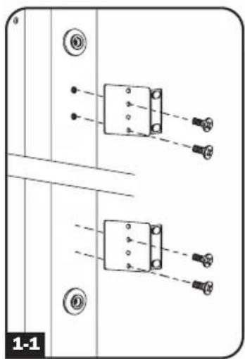
Note: The illustrations may differ somewhat from your PDU model. Regardless of configuration, the user must determine the fitness of hardware and procedures before mounting. The PDU and included hardware are designed for common rack and rack enclosure types and may not be appropriate for all applications. Exact mounting configurations may vary. Screws for attaching the mounting brackets and cord retention shelf to the PDU are included. Use only the screws supplied by Tripp Lite, or their exact equivalent.

Attach the mounting brackets to the PDU.

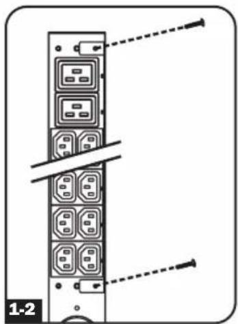
(Optional) Attach the cord retention bracket(s) to the PDU.

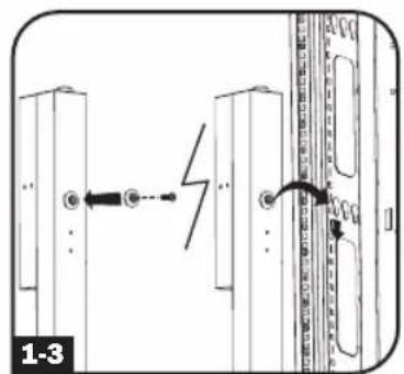
For toolless mounting, position the PDU as desired in the rack enclosure, align the buttons with the rack mounting slots, and slide the PDU into position.

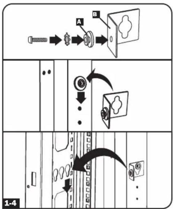
To install the PDU with its outlets facing the rear of the rack, use the included PDUMVROTATEBRKT accessory. First, attach the mounting button A to the V-shaped bracket B using the included screw and washer. Then, use the button-mount slot to attach the bracket to the PDU and the mounting button to attach the PDU to the rack. The bracket effectively repositions the mounting brackets, allowing for the PDU outlets to face the rear of the rack.

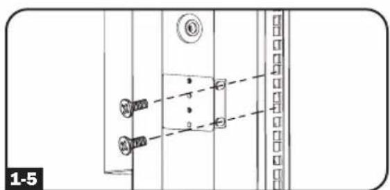
If your PDU cannot be mounted using the toolless mounting option, the mounting brackets can be used. Attach the PDU to a vertical rail in your rack or rack enclosure. (Use the mounting hardware that came with your rack or rack enclosure to attach the mounting brackets to the rail.)
Installation
Connecting the PDU
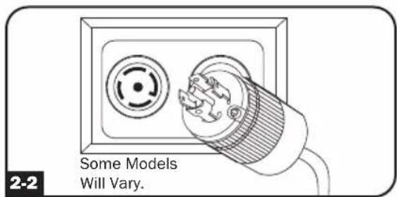
2-1 Each model is equipped with 1 of 5 different input plugs.


IEC 309 16A Red Hubbell CS8365C L21-30P L21-20P L22-20P (3P + N + E)
| Model # (Series Number) Input Plug | Max Amps | Input Voltage | Output Voltage | Balanced Output Current per Phase | Cord Length | Outlet Types Breakers | ||
| PDU3MV6L2120 (AGPD8414) | L21-20P 16A | 208V | 208V/ 120V | 9.2A | 6 ft. (1.8 m) | 36 x C13 (208V) 6 x C19 (208V) 6 x 5-15/20R (120V) | N/A | |
| PDU3MV6L2130 (AGPD8415) L21-30P 24A 208V | 208V/ 120V 13.9A | 6 ft. (1.8 m) | 36 x C13 (208V) 6 x C19 (208V) 6 x 5-15/20R (120V) | (3) 20A 2-POLE MAGNETIC | ||||
| PDU3V6L2130 (AGPD8415) L21-30P 24A | 208V/ 120V | 208V/ 120V 13.8A | 6 ft. (1.8 m) | 36 x C13 (208V) 6 x C19 (208V) 6 x 5-15/20R (120V) | (3) 20A 2-POLE MAGNETIC | |||
| PDU3MV6L2130A (AG-00E3) L21-30P 24A | 200V- 240V | 200V- 240V | 13.9A | 6 ft. (1.8 m) | 36 x C13 9 x C19 | (3) 20A 2-POLE MAGNETIC | ||
| PDU3V6H50 (AGPD8416) | Hubbell CS8365C | 35A 208V 208V 20.0A | 6 ft. (1.8 m) | 36 x C13 (208V) 9 x C19 (208V) | (3) 20A 2-POLE MAGNETIC | |||
| PDU3MV6H50 (AGPD8416) | Hubbell CS8365C | 35A 208V 208V 20.0A | 6 ft. (1.8 m) | 36 x C13 (208V) 9 x C19 (208V) | (3) 20A 2-POLE MAGNETIC | |||
| PDU3V6H50A (AGPD8417) | Hubbell CS8365C | 40A 208V 208V | 30A (L1-L2) 20A (L2-L3, L3-L1) | 6 ft. (1.8 m) | 36 x C13 (208V) 6 x C19 (208V) 3 x L6-30R (208V) | (2) 20A 2-POLE MAGNETIC(1) 30A 2-POLE MAGNETIC | ||
| PDU3MV6H50A (AGPD8417) | Hubbell CS8365C | 40A 208V 208V 20.0A | 6 ft. (1.8 m) | 36 x C13 (208V) 6 x C19 (208V) 3 x L6-30R (208V) | (2) 20A 2-POLE MAGNETIC(1) 30A 2-POLE MAGNETIC | |||
| PDU3V6L2120LV (AGPD8414) | L21-20P 16A | 208V/ 120V | 120V 9.2A | 6 ft. (1.8 m) | 42 x 5-15/20R (120V) | N/A | ||
| PDU3MV6L2120LV (AGPD8414) | L21-20P 16A | 208V 120V 9.2A | 6 ft. (1.8 m) | 42 x 5-15/20R (120V) | N/A | |||
| PDU3MV6L2120B (AGPD8414) | L21-20P 16A | 208V | 208V/ 120V | 9.2A | 6 ft. (1.8 m) | 6 x L6-20R (120V) 21 x 5-15/20R (120V) | N/A | |
| PDU3MV10L2120B (AGPD8414) | L21-20P 16A | 208V | 208V/ 120V | 9.2A | 10 ft. (3.05 m) | 6 x L6-20R (120V) 21 x 5-15/20R (120V) | N/A | |
| PDU3XV6G20 | IEC 309 16A Red (3P + N + E) | 16A | 360V- 415V | 208V- 240V | 16.0A | 6 ft. (1.8 m) | 36 x C13 (208V) 9 x C19 (208V) | N/A |
Installation
| Model # (Series Number) Input | Plug | Max Amps | Input Voltage | Output Voltage | Balanced Output Current per Phase | Cord Length | Outlet Types Breakers | |
| PDU3XMV6G20 (AGPD8420) | IEC 309 16A Red (3P + N + E) | 16A 36 | 0V-415V | 208V-240V | 16.0A | 6 ft. (1.8 m) | 36 x C13 (208V) 9 x C19 (208V) | N/A |
| PDU3XMV6L2220 (AGPD8420) | L22-20P 16A | 360V-4 | 15V | 208V-240V | 16.0A | 6 ft. (1.8 m) | 36 x C13 (208V) 9 x C19 (208V) | N/A |

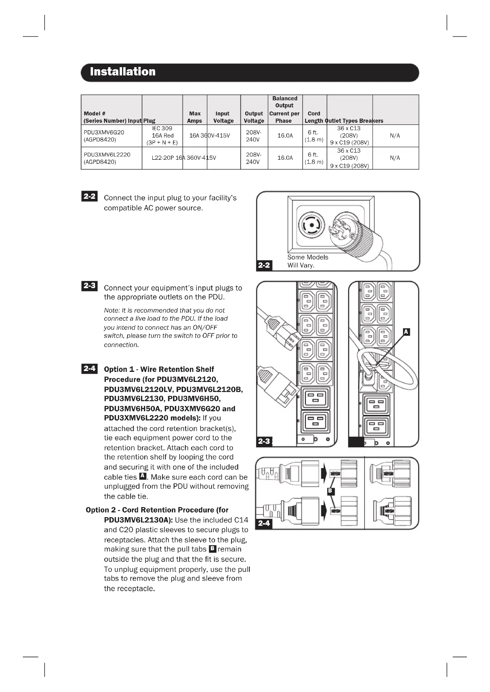
Connect the input plug to your facility's compatible AC power source.

Connect your equipment's input plugs to the appropriate outlets on the PDU.
Note: It is recommended that you do not connect a live load to the PDU. If the load you intend to connect has an ON/OFF switch, please turn the switch to OFF prior to connection.
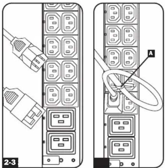

Option 1 - Wire Retention Shelf Procedure (for PDU3MV6L2120, PDU3MV6L2120LV, PDU3MV6L2120B, PDU3MV6L2130, PDU3MV6H50, PDU3MV6H50A, PDU3XMV6G20 and PDU3XMV6L2220 models): If you
attached the cord retention bracket(s), tie each equipment power cord to the retention bracket. Attach each cord to the retention shelf by looping the cord and securing it with one of the included cable ties A. Make sure each cord can be unplugged from the PDU without removing the cable tie.
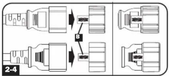
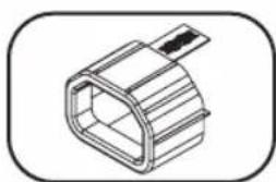
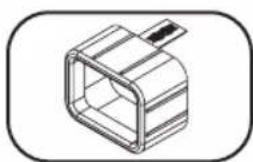
Option 2 - Cord Retention Procedure (for
PDU3MV6L2130A): Use the included C14 and C20 plastic sleeves to secure plugs to receptacles. Attach the sleeve to the plug, making sure that the pull tabs remain outside the plug and that the fit is secure. To unplug equipment properly, use the pull tabs to remove the plug and sleeve from the receptacle.
Digital Load Meter (Select Models Only)
Input Amps: The total aggregate current (in Amps) drawn by each of the PDU phases will be displayed independently by 1 of 3 digital meters.
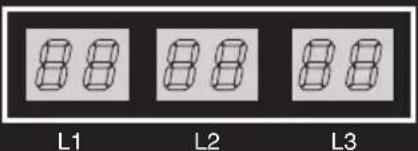
INPUT (AMPS)

(PDU3MV6L2120, PDU3MV6L2130, PDU3MV6L2120B)
Load Amps: The total aggregate current drawn (in Amps by the load bank associated with each phase will be displayed independently by 1 of 3 digital meters.
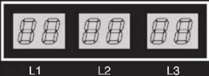
LOAD (AMPS)

(PDU3MV6L2120LV, PDU3XMV6G20, PDU3XMV6L2220)
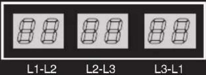
LOAD (AMPS)

(PDU3MV6H50, PDU3MV6H50A, PDU3MV6L2130A)
Features
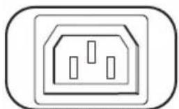
IEC-60320-C13
Outlets: During normal operation, the outlets distribute AC power to connected equipment.
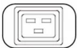
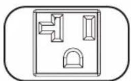
IEC-60320-C19 NEMA 5-15/20R 20 amp (208V)

NEMA L6-20R

30 amp (208V)
NEMA L6-30R
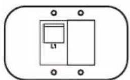
Circuit Breaker (Select Models): Each phase has its own breaker. If the connected equipment load exceeds the Maximum Load Rating for that phase of the PDU, the circuit breaker will trip. Disconnect excess equipment and allow the breaker to cool before resetting the breaker.
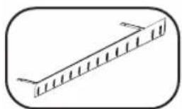
Cord Retention Bracket: Provides secure attachment points for connected equipment cords.
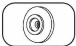
Mounting Buttons: Come pre-installed on the back side of the PDU and are used for toolless mounting. Note: Four additional mounting buttons are included for alternate rack styles.
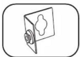
PDUMVROTATEBRKT Mounting Accessory: Use these V-shaped brackets to mount the PDU with its outlets facing the rear of the rack.
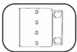
Mounting Brackets: Use these brackets to mount the PDU in racks that are not compatible with toolless button mounting methods.

Ground Screw: Use this to connect any equipment that requires a chassis ground.
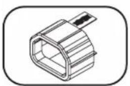
C14 Plug Sleeve: (Optional) Use the included C14 plastic sleeves to secure plugs to receptacles. Attach the sleeve to the plug, making sure that the pull tabs remain outside the plug and that the fit is secure. To unplug equipment properly, use the pull tabs to remove the plug and sleeve from the receptacle.

C20 Plug Sleeve: (Optional) Use the included C20 plastic sleeves to secure plugs to receptacles. Attach the sleeve to the plug, making sure that the pull tabs remain outside the plug and that the fit is secure. To unplug equipment properly, use the pull tabs to remove the plug and sleeve from the receptacle.
Service
Your Tripp Lite product is covered by the warranty described in this manual. A variety of Extended Warranty and On-Site Service Programs are also available from Tripp Lite. For more information on service, visit tripplite.com/support. Before returning your product for service, follow these steps:
- Review the installation and operation procedures in this manual to ensure that the service problem does not originate from a misinterpretation of the instructions.
- If the problem continues, do not contact or return the product to the dealer. Instead, visit tripplite.com/support.
- If the problem requires service, visit tripplite.com/support and click the Product Returns link. From here you can request a Returned Material Authorization (RMA) number, which is required for service. This simple on-line form will ask for your unit's model and serial numbers, along with other general purchaser information. The RMA number, along with shipping instructions will be emailed to you. Any damages (direct, indirect, special or consequential) to the product incurred during shipment to Tripp Lite or an authorized
Tripp Lite service center is not covered under warranty. Products shipped to Tripp Lite or an authorized Tripp Lite service center must have transportation charges prepaid. Mark the RMA number on the outside of the package. If the product is within its warranty period, enclose a copy of your sales receipt. Return the product for service using an insured carrier to the address given to you when you request the RMA.
Warranty and Product Registration
2- YEAR LIMITED WARRANTY
Seller warrants this product, if used in accordance with all applicable instructions, to be free from original defects in material and workmanship for a period of 2 years from the date of initial purchase. If the product should prove defective in material or workmanship within that period, Seller will repair or replace the product, in its sole discretion. Service under this Warranty can only be obtained by your delivering or shipping the product (with all shipping or delivery charges prepaid) to: Tripp Lite, 1111 W. 35th Street, Chicago, IL 60609 USA. Seller will pay return shipping charges. Visit triplite.com/support before sending any equipment back for repair.
THIS WARRANTY DOES NOT APPLY TO NORMAL WEAR OR TO DAMAGE RESULTING FROM ACCIDENT, MISUSE, ABUSE OR NEGLECT. SELLER MAKES NO EXPRESS WARRANTY OTHER THAN THE WARRANTY EXPRESSLY SET FORTH HEREIN. EXCEPT TO THE EXTENT PROHIBITED BY APPLICABLE LAW, ALL IMPLIED WARRANTYES, INCLUDING ALL WARRANTYES OF MERCHANTABILITY OR FITNESS, ARE LIMITED IN DURATION TO THE WARRANTY PERIOD SET FORTH ABOVE; AND THIS WARRANTY EXPRESSLY EXCULES ALL INCIDENTAL AND CONSEQUENTIAL DAMAGES. (Some states do not allow limitations on how long an implied warranty lasts, and some states do not allow the exclusion or limitation of incidental or consequential damages, so the above limitations or exclusions may not apply to you. This Warranty gives you specific legal rights, and you may have other rights which vary from jurisdiction to jurisdiction).
WARNING: The individual user should take care to determine prior to use whether this device is suitable, adequate or safe for the use intended. Since individual applications are subject to great variation, the manufacturer makes no representation or warranty as to the suitability or fitness of these devices for any specific application.
PRODUCT REGISTRATION
Visit tripplite.com/warranty today to register your new Tripp Lite product.You'll be automatically entered into a drawing for a chance to win a FREE Tripp Lite product!*
- No purchase necessary. Void where prohibited. Some restrictions apply. See website for details.
FCC Notice, Class A
This device complies with part 15 of the FCC Rules. Operation is subject to the following two conditions: (1) This device may not cause harmful interference, and (2) this device must accept any interference received, including interference that may cause undesired operation.
Note: This equipment has been tested and found to comply with the limits for a Class A digital device, pursuant to part 15 of the FCC Rules. These limits are designed to provide reasonable protection against harmful interference when the equipment is operated in a commercial environment. This equipment generates, uses, and can radiate radio frequency energy and, if not installed and used in accordance with the instruction manual, may cause harmful interference to radio communications. Operation of this equipment in a residential area is likely to cause harmful interference in which case the user will be required to correct the interference at his own expense.
The user must use shielded cables and connectors with this equipment. Any changes or modifications to this equipment not expressly approved by Tripp Lite could void the user's authority to operate this equipment.
Regulatory Compliance Identification Numbers
For the purpose of regulatory compliance certifications and identification, your Tripp Lite product has been assigned a unique series number. The series number can be found on the product nameplate label, along with all required approval markings and information. When requesting compliance information for this product, always refer to the series number. The series number should not be confused with the marking name or model number of the product.
WEEE Compliance Information for Trlpp Lite Customers and Recyclers (European Union)
Under the Waste Electrical and Electronic Equipment (WEEE) Directive and implementing regulations, when customers buy new electrical and electronic equipment from Tripp Lite they are entitled to:
- Send old equipment for recycling on a one-for-one, like-for-like basis (this varies depending on the country)
- Send the new equipment back for recycling when this ultimately becomes waste
Tripp Lite has a policy of continuous improvement. Specifications are subject to change without notice. Photos and illustrations may differ slightly from actual products.

TrippLite.Eaton.com/support
MOHTaXbIe KPOHtTeuHbI: 3TN KPOHtTeuHbICnEpyET NcONb3OBAbT dIa MoHTaKa PDU B cToKn, He nOaxoJxue nIa MoHTaKa Ha 3aUeKn 6e3 nOMouN IHCTpyMeHToB.

BnHT 3aemneHn: nCIOJIb3yETcI IN CoeINHeHn C IIO6bIM o6OpyIDOBaHnEM, Tpe6yUoMm 3aemneHn waccn.
Myfpa pa3bema C14: (onu) 3aФNKcnpyTe pa3bembl B po3eTkax npn nomou BxOJrux B KOMNKeT nlaCTMaCCOBbIX Myf TIOB pa3bembl C14. PpIKpeNITE MyfK pa3bemy, y6eINBmcb TOM, YTO ee Ra3bUKN OCTaIOTc 3a npedanm pa3bema I NIOTHO npnIeraIOT K Hemy. Jn npabunbHoro OTCoeDInHeHHo 06OpuyoBaHnCneDyET BbIHMaTb pa3bem C MyfToI N3 po3eTKn, DePjAc b 3a Ra3bIKN.
Myfpa pa3bema C20: (onu) 3aФKcpyTe pa3bembIB po3eTkax npn nomoBxOJRAUX B KOMNKeT NlaCTMaccOBbIX MyfT NOI pa3bembIC20. PpIKpenITE MyfTy K pa3bemy, y6eINUBmCB B TOM, YTO ee r3bUKN OCTaOTcA 3a npedeJaMa pa3bema I NIOTHO INPnJIeAOT K Hemy. JIy npabunlbHoro OTcoEINHeHnO6OpyDobAHn CneJeT BblHMaTb pa3bEm C MyfToI N3 po3eTK, Depxacb 3a r3bUKN.
TexHnueckoe 06cnyxmbaHne
Ha npno6pehenhoe Bamn n3dene Mapkn Tripp Lite pacnpoctpaHne Tce nctBne rapaHTn, ycnobn KOTopoN n3loKeHb B hactoIe pykoBOcTBe. Kpome TOrO, kOMnaHn Tripp Lite npednaraet pnd PporpaMm pacwnpeHHo rapaHTn n o6clyKmbaHn Ha o6bkeTe. BoJee noDpo6Na HnΦopMaun O texHNueckom o6clyKmbaHn n3loXeHa Ha cTpaHnue www.triplite.com/support. Ipeed BO3bpatom CBOero n3dennBa CEJx TexHNueckoro 06clyKmbaHn npoc6ba BblONHtB cNe dyUOnne deiCTBN:
-
BHIMATEbHO n3yHTe nopraOK yctAHOBKn 3KcNpyataaun yCTPOcTBa, npuBEeHHbI B HactoIeM pyKOBOCTBe, BO n36exKaHHe pO6JIe, KOtOpBte MOrY T Bo3HNKHyTb B XoJe pa60Tb I3-3a HnpabINbHO rONHMAnr npuBeDEHbIX B pyKOBOCTBe yKa3AHn.
-
Ecn npo6nemy peuHb He ydaNoCb, He obaaTecb K npoabuy H He Bo3BpaauTe n3dene my. B 3Tom cnyae nocetnte INHTepHET-CTpAHNy no aDpcy: www.triplite.com/support.
-
EcnB O3HnKsA np6bema Tpe6yeT npoBeHnra pemOnTa nIi TexHnueckoro 06cnykBaHnra, 3aInTe Ha cTpaHnUy www.triplite.com/support n Haxmnte Ha cSbIKy Product Returns (Bo3Bpat n3denn). 3deB Bbl MoKeTe 3anpocntb Homep Returnedred Material Authorization (RMA) (pa3peuHne Ha Bo3Bpat MaTePnaNoB), KOTOpB Heo6xoDum dI npoBeHnra TexHnueckoro 06cnykBaHnra. Dnla 3anONHeHn 3ToI npOCToH ONaH-OpMbI Ntpe6yeTcY kAsaTb Homep moEiN u cepHnBnHomep BaWero n3denn, a Takke obune CbeHnra O nokynatele. Homep RMA BmeCe C yka3aHnmaN no TpaHCnpTnpOBke 6ydt HapabEn Bam NO 3JeKTPoHHo Noute. Ha KaKne 6bI To Hn 6bIIO y6bITKn (PpAmbie, KOCBeHHbIe, IocNeIyUOJIe NII Bb3BaHHbIe Oco6bIM NoCSTOATENBCTBaMn), CBzAHHbIe C TpaHCnpTnpOBkoN n3denn B aDpc KOMNaHN Tripp Lite nIIe ee yonlHomoeHHORo cepBnCHORO ueHTpa, DeINCTBNE rapaHTNI He pacnpoctpaHReTc. CTOMOCTb TpaHCnpTnpOBKn n3denn B aDpc KOMNaHN Tripp Lite nIIe ee yonlHomoeHHORo cepBnCHORO ueHTpa DOJXHa 6bITb ONaueHa abAHcom. Homep RMA DoJxen 6bITb Yka3An Ha BHeHne CTopoNE yNAKOKN. EcnB O3Bpat n3denn npoIN3BODITcB INepNOd JeinCTBnRA rapaHTNI, TO Heo6xoDIm pniINOxNtB KOJIIO TOBAPHOrO yeKa npodAbua. Bo3Bpat n3denn dI npoBeHnra peMOHTa nII IN texHHueCKoro 06cnykBaHnra DOJxKe H npoIN3BODITbc3actpaxOBaHHbIM nepeBO3UnKOM no aDpcy, yka3aHHOMy B OTBeTe Ha BaW 3anpoc Homepa RMA.
TapaHTnHbIe 6a3aTeNbCTBa n peRnCTpaZna rapaHTn
OTPAHNUEHHHA TAPAHNTN CPOKOM HA 2 TODA
IpoaBeu rapaHTnpyET OTCYCTBnE N3HauAibhBix DeeKTOB MaTePnAna IIN I3rOToBHeHn B TeueHne 2 let C MOMENTa nepBOI NOKUKN DaHHORIO IN3dJIIN Pn YCIOBUN ERO NcNOJbOBAHn B COOTBECTBNCO BCEMN npIMEHMBIM K HEmy yka3AHmMn. B cnyae pnoBHeHn KaNX-16o DeeKTOB MaTePnAna IIN I3rOToBHeHn B TeueHne yka3AHnO nepNoIpaDBeU OcyueCTBnEeT peMOHT IIN 3aMeHy daHHORIO IN3dJIEN IckNUOpHTnbHO NO CBOEMY yCMOTpeHnIO. ObcnykBaHne IO NaHctOJeI TapaHTNI pOni3BOJNTc TOlbKO pIn yCIOBUN DOCTABKN IIN OTnpaBVKn Bam6pakOBaHHOrO IN3dJIEN (c npedBapntelHoONlatoBcEx paXoOB no erO tpaHCnOpTIpOBKe IIN doCTabke) no aDpecy: Tripp Lite, 1111 W. 35th Street, Chicago, IL 60609 USA. PaXoDbI no o6paTHoTpaHCnOpTIpOBKe IN3dJIIN ONNaHbAOTc PpOaBuOM. Ipeed BozBpatom IIO6Oro O6OpyDoBaHn DIA IPOBeHnpeMOHT O3HaKOMbTecb C nHfOpMaUne Ha CTpaHnue www.triplite.com/support.
JECTBNE HACTOJI E IAPAHTNHE PACNPOCTPAHRETCA HA CJIYAH ECTECTBEHHOTO 3HOCA INIIOBPEKJDEHNA BPE3YJbTATE ABAPIN, HEHAJIENJAECIIOJIOBJ3OBAHN, HAPUWEHNI PPABINJ 3KCIIVYATAUINI INI XAIATHOCTN.IPOJABEUHE NPEIOCTABJREHIKAKNX YBHO BbIPAXEHHBIX TAPAHTNI 3A NCKJIIOUCHENEM PJPMO N3LOXKEHHOH B HACTOJIEM DOKUMEHE.3A NCKJIIOUCHENEM CJIYAAEB, 3ANPEUHEHHBX DEIECTBYIOUIM 3AKOOHDATEJBCTBOM, BCE NOJDA3YMBAEMBIE TAPAHTNI, BKIIIOUAR BCE TAPAHTN INPIROIDHOCTNДЛЯ ПОДAJX INI INCNOJb3OBAHN IO HA3HAUEHNIO, OPHAUNHbI IO PINOJOLKNTELbHOCTN DEICTBNA BbIeYKA3AHbIM TAPAHTNbIM CPOKOM; KPOME TOFO, IN3 HACTOJI E TAPAHTN JRBbIM O6P2A3OM NCKLIQUAOTCR BCE IIOBOUYBE, CJYAAHbIE IN KOCBEHHbIE YbITKN. (B HeKOToBPbix Wtatax He DoynckaeTc BBeDeHne OrpaHnueHn Ha npoJOnkTeNbHOCTB DeiCTBn Tex INI INhIX NpOpa3ymeBaembIX rapaHTN, a B HeKOToBPbIX - NCKLIQUeHne INI ORpaHnueHne pa3Mepa no6OuHbIX INI KOCBeHHbx y6bITKOB. B 3TNX Cnyaax Bbienn3LOXeHNBie OrpaHnueHn INI NCKLIQUeHn MOrYT Ha Bac He paCnpocTpAnrbc. HactoJaua TapaHTN npeoCTabJIeT Bam KOHKpeTHbIe IOpNJueeCKNe npaba, a Na6Op dpynx Baunx npab MoKeT 6b1b pa3NJuHbIM B 3aBNCIMOCnT OT IpucndNKUn).
BHIMAHIE! Do nauana nCnObl3OBaHnna daHHoro yctpoiCTBa nObl3OBaTeNb doJKeH y6eIITbCS B TOM, uTO OHO YBJIeTcra npiroDnHM, COOTBeTCTByIOUm INI 6e3oNaChM dI pypeINoNAeMORO npimHeHn. B CBAIc C 6OJIbWM pa3HOO6pa3NEM KOHKpeTHbIX npimeHEN Ipon3BOuNTeNB He daET KaNX-JIbO 3abepHn INI rapaHTMI OTHCtIELBO npiroDnHOCTn DaHHbx INIdEJIIM dIy KaKOr-OJIbO KOHKpeTHO npimHeHn INI INX COOTBECTBnRA KaKIM-JIN60 KOHKpeTHbIM Tpe6OBAHnM.
IeHTnKauNHOHbIe HOMepa COOTBcTcBn HOpMaTHBbIM Tpe6oBaHnA
B cTnHnKauHn H COOTBeTCTBHe HOpMaTHBbIM Tpe6oBaHnM n OTO3HaBaHnI pnpO6peTeHHOMy BAMn I3dJIIO MapKn Tripp Lite npncBOeH yHnKaIbHbI cepuHbI Homep. CepuHbI Homep pacnoIaerTcH a 3aBoDcKo Ta6NIue BMeCTe co BCemn Heo6XoDMbIM OTMeTKaMn O npneMke n IpOce uHfOpMaueN. Ppi 3apoc E HOpMaUIN O COOTBeTCTBn DaHHOr O hDJIeNHO HopMaTbHBm Tpe6oBaHnM o63aTeJIbHo yKa3bIaBte erO cepuHbI Homep. CepuHbI Homep He cIedyET nyTaTb C haImeHOBaHnEM MapKn I3dJIeN UIn Homepom erO moJIeN.
HOpMaunnoBbONHeHHIO Tpe6oBaHm DnpeKTHBbI WEEE nI NOkynateJe N nepepa60TuNKOB npOdyKcnn KOMNaHm Tripp Lite (Abnlouuxcpe3nEHTAmn Ebponeckoro Co103a)
Corglachno noloxhenm Dnpekntbbl o6 ytnin3aun OTxodOB 3neKtpueeCKOr O 3neKtpoHHoro 06opuydoBaHna (WEEE) nncnHnTeIhBbIX paonopjxeHn no ee npimHeHIO, pni NOKyInke nOtpe6nteHm HOBO rNeKtpueeCKOr Hnn 3neKtpoHHoro 6OpuydoBaHn npOn3BODCTBA KOMnHn Tripp Lite OHn nonyaiaot npabo Ha:
- PpOdaJy cIaporo 06OpUdoBaHn no npuHcNpy "Ounn K OOnHy" n/nn Ha 3KbBaeHTHOOCHOBE (B 3aBNCIMocTn OT KOHNpeTHOH CTpaHbI)
- Otnpabky HOBORO 60pydOBaHnHa nepepa60kny nocle okOHaTebHOB bIpa60TK er opecypca
KomnaHn Tripp Lite noctoHH coBepseHcTByET cBOIO npOdyKuIO. B cBa3N C 3TMM BO3MOXHO n3MeHeHne TexHuecknx xapaTepeNk 6e3 npEbpntenbHorO yBeOMHeH.N BHeHn Bn peaBbIX n3denn MoKeT HeCKoJIbKO OTIIuATbcraOT pEcdTabLeHHoro Ha oToTporpaHnx nIINIOCTpaunx.

TrippLite.Eaton.com/support