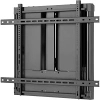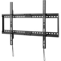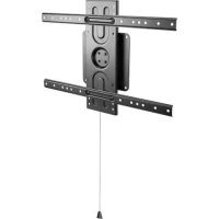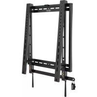
DWFPSC4570M - TV wall mount Tripp Lite - Free user manual and instructions
Find the device manual for free DWFPSC4570M Tripp Lite in PDF.


User questions about DWFPSC4570M Tripp Lite
0 question about this device. Answer the ones you know or ask your own.
Ask a new question about this device
Download the instructions for your TV wall mount in PDF format for free! Find your manual DWFPSC4570M - Tripp Lite and take your electronic device back in hand. On this page are published all the documents necessary for the use of your device. DWFPSC4570M by Tripp Lite.
USER MANUAL DWFPSC4570M Tripp Lite
Register your product for quicker service and ultimate peace of mind. You could also win an ISOBAR6ULTRA surge protector—a \$100 value!
www.tripplite.com/warranty

text_image
TRIPP·LITE
1111 W. 35th Street, Chicago, IL 60609 USA • www.tripplite.com/support
Copyright © 2019 Tripp Lite. All rights reserved.

WARNING
- Do not begin the installation until you have read and understood the instructions and warnings contained in this manual. If you have any questions regarding any of the instructions or warnings, please visit www.tripplite.com/support.
- This mounting bracket was designed to be installed and utilized ONLY as specified in this manual. Improper installation of this product may cause damage or serious injury.
- This product should only be installed by someone of good mechanical ability, with basic building experience and a full understanding of this instruction manual.
- Make sure that the mounting surface can safely support the combined load of the equipment and all attached hardware and components.
- If mounting to wood wall studs, make sure that mounting screws are anchored into the center of the studs. The use of a stud finder is highly recommended.
- Always use an assistant or mechanical lifting equipment to safely lift and position equipment.
- Tighten screws firmly, but do not over-tighten. Over-tightening can damage the items, greatly reducing their holding power.
- This product is intended for indoor use only. Using this product outdoors could lead to product failure and personal injury.
Warranty & Product Registration
5-Year Limited Warranty
Seller warrants this product, if used in accordance with all applicable instructions, to be free from original defects in material and workmanship for a period of 5 years from the date of initial purchase. If the product should prove defective in material or workmanship within that period, Seller will repair or replace the product, in its sole discretion.
THIS WARRANTY DOES NOT APPLY TO NORMAL WEAR OR TO DAMAGE RESULTING FROM ACCIDENT, MISUSE, ABUSE OR NEGLECT. SELLER MAKES NO EXPRESS WARRANTIES OTHER THAN THE WARRANTY EXPRESSLY SET FORTH HEREIN. EXCEPT TO THE EXTENT PROHIBITED BY APPLICABLE LAW, ALL IMPLIED WARRANTIES, INCLUDING ALL WARRANTIES OF MERCHANTABILITY OR FITNESS, ARE LIMITED IN DURATION TO THE WARRANTY PERIOD SET FORTH ABOVE; AND THIS WARRANTY EXPRESSLY EXCLUDES ALL INCIDENTAL AND CONSEQUENTIAL DAMAGES. (Some states do not allow limitations on how long an implied warranty lasts, and some states do not allow the exclusion or limitation of incidental or consequential damages, so the above limitations or exclusions may not apply to you. This warranty gives you specific legal rights, and you may have other rights which vary from jurisdiction to jurisdiction).
WARNING: The individual user should take care to determine prior to use whether this device is suitable, adequate or safe for the use intended. Since individual applications are subject to great variation, the manufacturer makes no representation or warranty as to the suitability or fitness of these devices for any specific application.
PRODUCT REGISTRATION
Visit www.triplite.com/warranty today to register your new Tripp Lite product. You'll be automatically entered into a drawing for a chance to win a FREE Tripp Lite product!*
* No purchase necessary. Void where prohibited. Some restrictions apply. See website for details.
Tripp Lite has a policy of continuous improvement. Specifications are subject to change without notice.
Component Checklist
IMPORTANT: Ensure all parts according to the component checklist have been received prior to installation. If any parts are missing or faulty, visit www.tripplite.com/support for service.
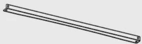
natural_image
Simple line drawing of a two parallel metal rod or support structure (no text or symbols)Vertical Wall Plate (x2)
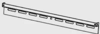
natural_image
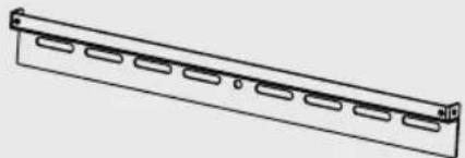
Technical line drawing of a mechanical component with multiple slots and a flat base (no text or symbols)Horizontal Wall Plate (x2)
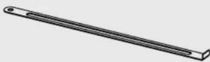
natural_image
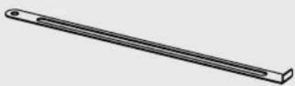
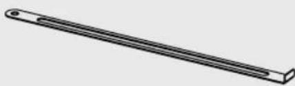
Simple line drawing of a long rectangular object with a small circular end (no text or symbols)Security Bar (x1)
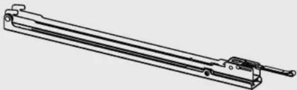
natural_image
Technical line drawing of a mechanical lever assembly (no text or symbols)Adapter Bracket (x2)

M5 x 8 Screw (x8) Bubble Level (x1) Combo Lock (x1)

Package M

M5 x 14 Screw (x4)
M6 x 14 Screw (x4)
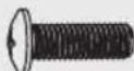
M8 x 20 Screw (x4)
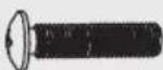
M6 x 30 Screw (x4)
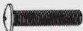
M8 x 30 Screw (x4)
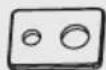
Washer (x4)

Small Spacer (x8)

Big Spacer (x8)
Package W

Anchor Bolt (x6)
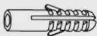
Concrete Anchor (x6)
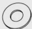
D6 Washer (x6)
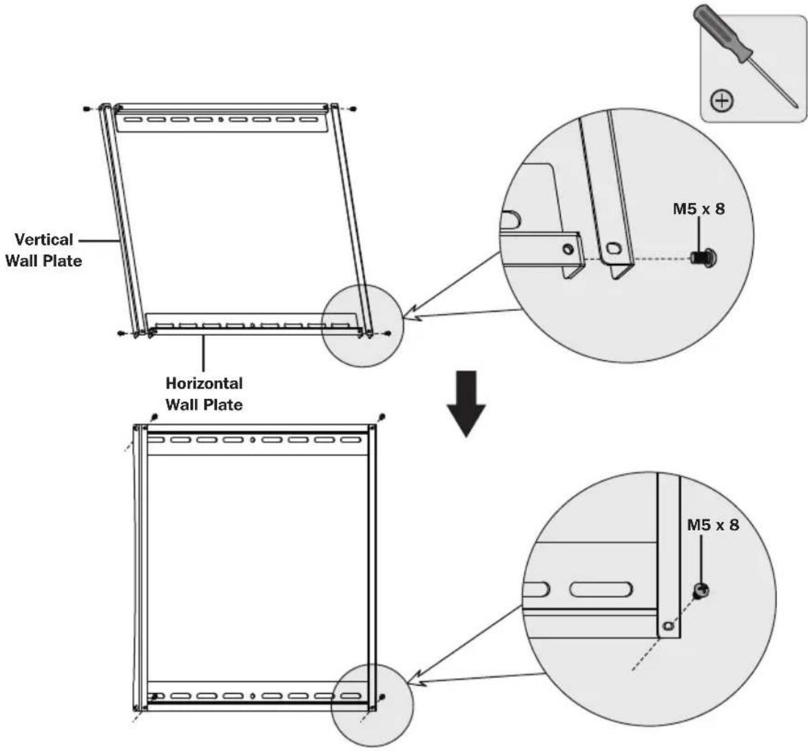
1. Assemble the Wall Plate
text_image
Vertical Wall Plate Horizontal Wall Plate M5 x 8 M5 x 8Attach the vertical wall plates to the horizontal wall plates using the appropriate screws. Tighten all screws with a proper screwdriver.

text_image
Bubble Level2a. Mount on Wood Stud Wall
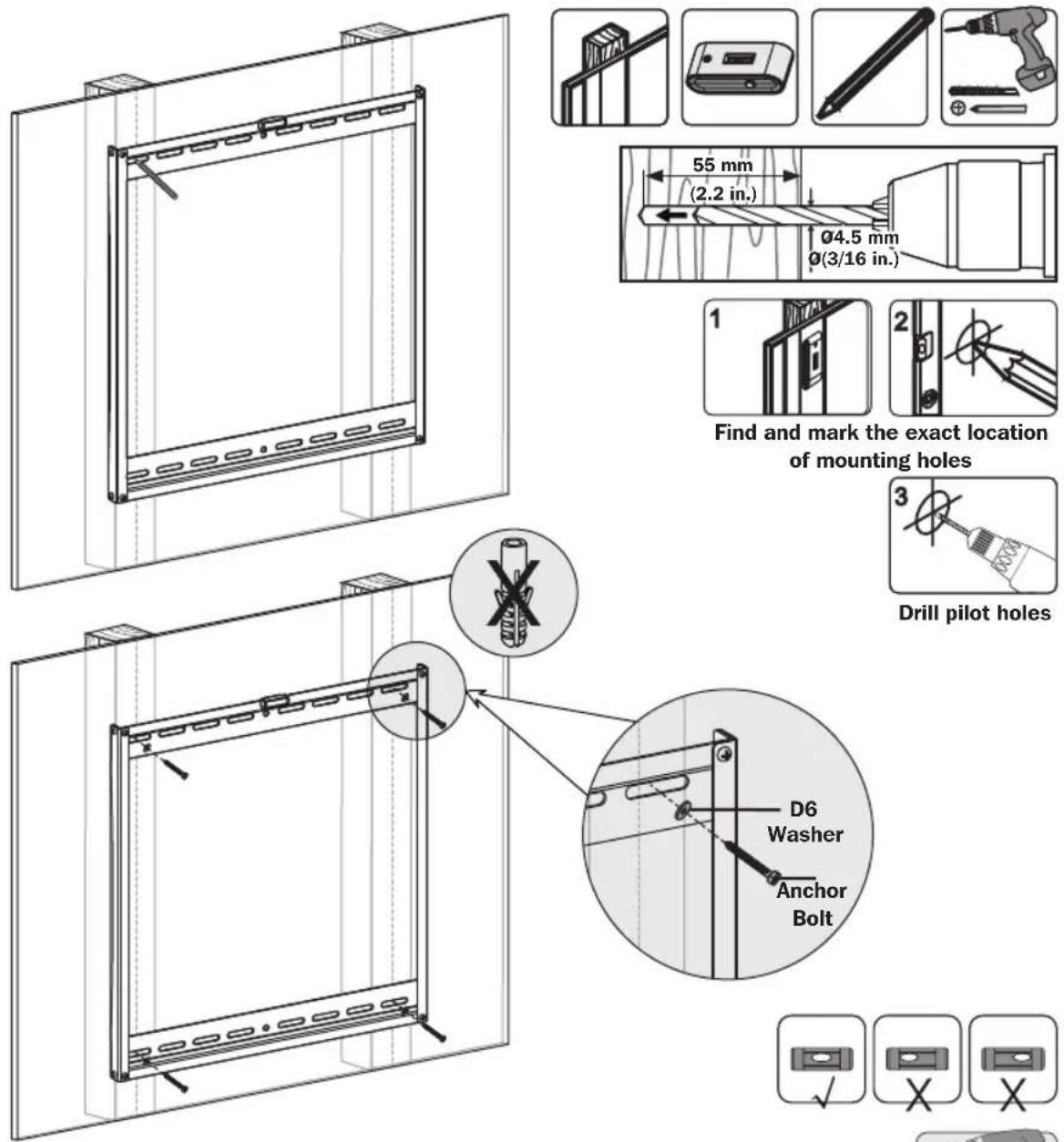
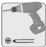
Screw the assembled wall plate onto the wall
WARNING
- Make sure that mounting screws are anchored into the center of the studs. Use of a stud finder is highly recommended.
• Installers are responsible to provide hardware for other types of mounting situations.
• Installers must verify that the supporting surface will safely support the combined load of the equipment and all attached hardware and components.
2b. Mount on Solid Brick and Concrete Block
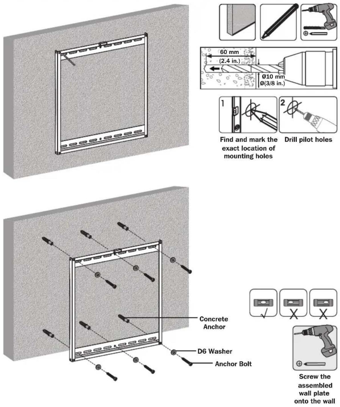
WARNING
- When installing wall mounts onto a concrete masonry unit (also known as a CMU or "cinder block"), verify that the actual concrete thickness is at least 35 mm (1-3/8") in order to hold the concrete anchors. DO NOT DRILL INTO MORTAR JOINTS! Be sure to mount the assembled wall-mount plate with the included concrete anchors, D6 washers and anchor bolts onto solid sections of the blocks. The solid sections can generally be found 25 mm (1") toward the middle of the block from either end. An electric drill on a slow setting is suggested to drill the hole rather than a hammer drill so as to avoid breaking out the back of the hole when entering a hollow section.
• Installers must verify that the supporting surface will safely support the combined load of the equipment and all attached hardware and components.
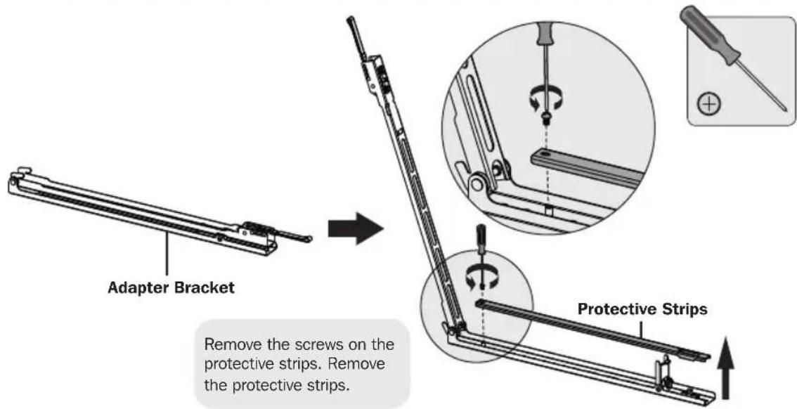
3. Install Adapter Brackets
text_image
Adapter Bracket Remove the screws on the protective strips. Remove the protective strips. Protective Strips3a. For Flat Back Screen
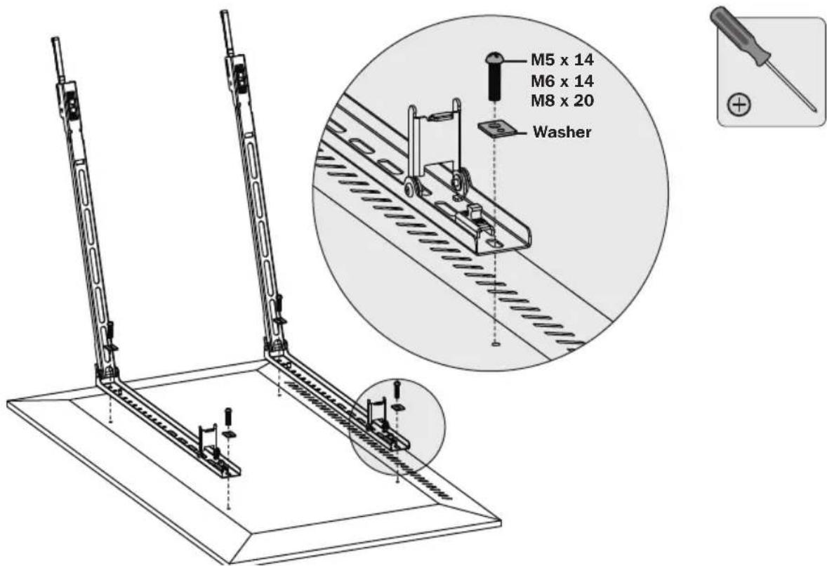
text_image
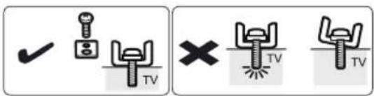
M5 x 14 M6 x 14 M8 x 20 WasherNote: Choose appropriate screws, washers and spacers (if necessary) according to the type of screen.
- Position the adapter brackets as close as possible to the center of the display.
- Screw the adapter brackets onto the display.

Firmly secure all screws. Do not over-tighten.
text_image
Diagram showing TV lighting symbols with checkmark and cross icons for lighting application3. Install Adapter Brackets
3b. For Protruded or Recessed Back Screen

natural_image
Technical line drawing of a mechanical assembly with mounting brackets and a circular component (no text or symbols)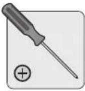

text_image
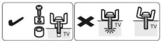
M6 x 30 M8 x 30 Washer M6 x 30 M8 x 30 or Washer Small Spacer Big Spacer M8 x 20 Washer Washer Small Spacer M6 x 30 M8 x 30 Small SpacerNote: Choose appropriate screws, washers and spacers (if necessary) according to the type of screen.
- Position the adapter brackets as close as possible to the center of the display.
- Screw the adapter brackets onto the display.

Firmly secure all screws. Do not over-tighten.
text_image
Technical diagram showing three types of TV lighting fixtures with check and cross icons indicating inspection or testing conditions.3. Install Adapter Brackets
3b. For Protruded or Recessed Back Screen (continued)

text_image
Reattach the protective strips to the adapter brackets using the previously removed screws. Protective Strips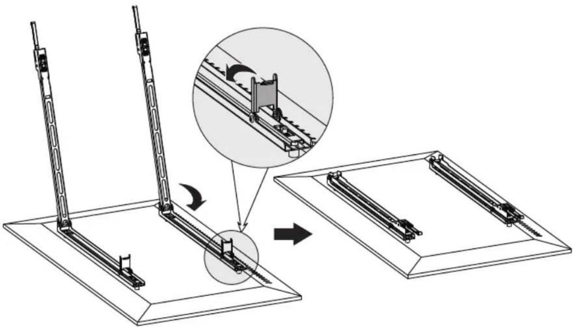
text_image
Technical diagram illustrating a mechanical assembly process with labeled components and directional arrows indicating motion or assembly.- Hang Display onto the Wall Plate
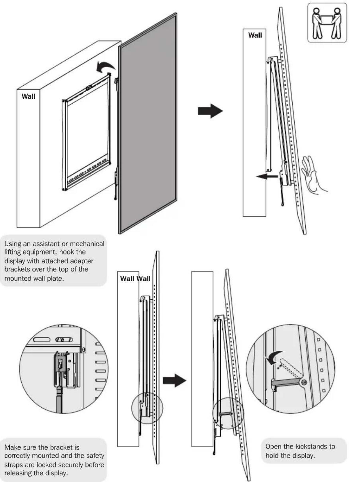
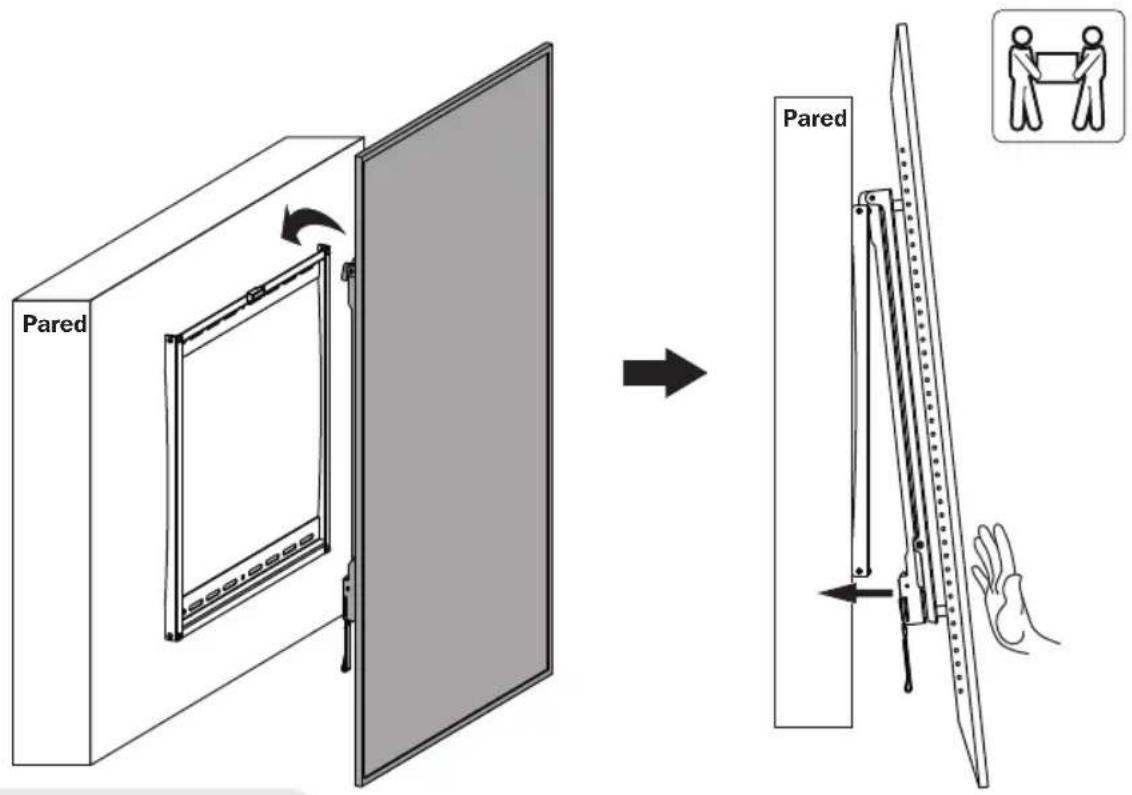
Using an assistant or mechanical lifting equipment, hook the display with attached adapter brackets over the top of the mounted wall plate.
Make sure the bracket is correctly mounted and the safety straps are locked securely before releasing the display.
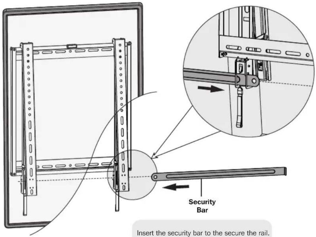
5. Slide Security Bar through the Mounting Brackets and Attach Combo Lock to Secure
text_image
Security Bar Insert the security bar to the secure the rail.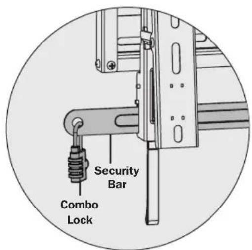
text_image
Security Bar Combo Lock
natural_image
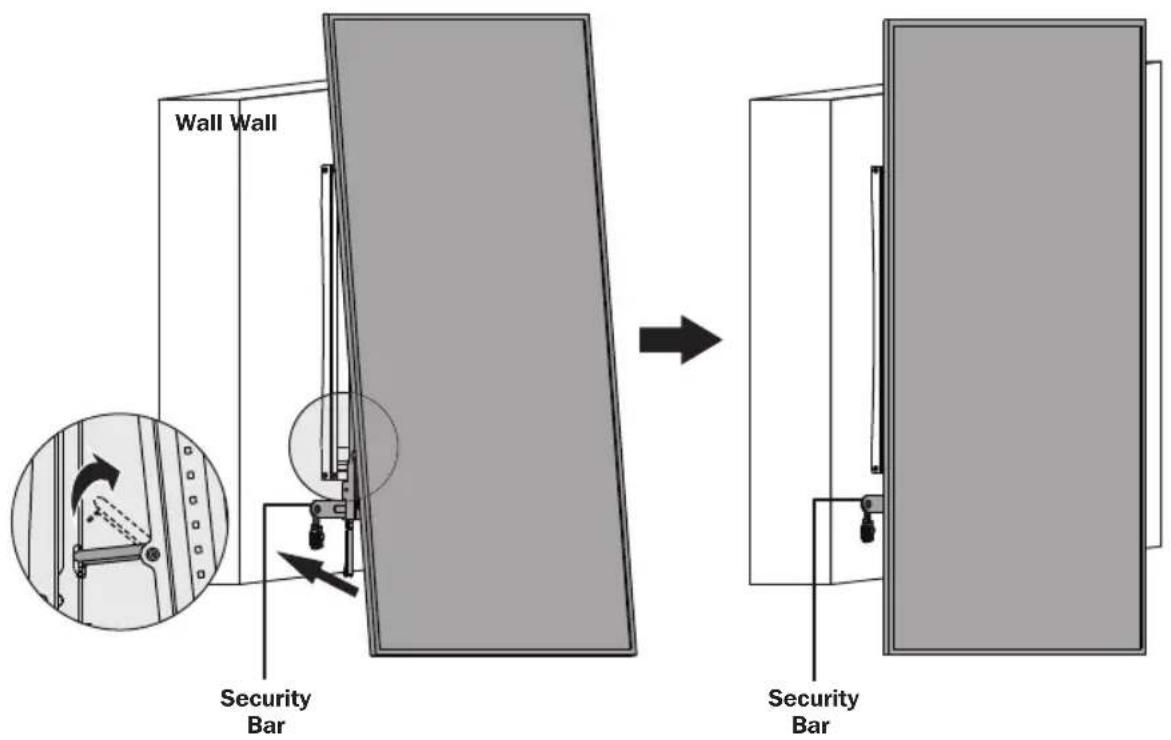
Technical line drawing of a mechanical frame assembly with mounting brackets and a close-up inset showing a connector detail (no text or symbols)- Slide Security Bar through the Mounting Brackets and Attach Combo Lock to Secure
text_image
Wall Wall Security Bar Security BarFold the kickstands after finishing the security bar installation.
6. Removing the Display

flowchart
graph TD
    A["Wall"] --> B["Adder Frame"]
    B --> C["Adjusting Security Bar"]
    C --> D["Remove the security bar. Pull the two straps down to unlock the adapter brackets from the wall plate assembly."]
    D --> E["Adder Frame"]
    E --> F["Adjusting Security Bar"]
    F --> G["Remove the security bar. Pull the two straps down to unlock the adapter brackets from the wall plate assembly."]
    G --> H["Adder Frame"]
    H --> I["Adjusting Security Bar"]
    I --> J["Remove the security bar. Pull the two straps down to unlock the adapter brackets from the wall plate assembly."]
    J --> K["Adder Frame"]
    K --> L["Adjusting Security Bar"]
    L --> M["Remove the security bar. Pull the two straps down to unlock the adapter brackets from the wall plate assembly."]
    M --> N["Adder Frame"]
    N --> O["Adjusting Security Bar"]
    O --> P["Remove the security bar. Pull the two straps down to unlock the adapter brackets from the wall plate assembly."]
    P --> Q["Adder Frame"]
    Q --> R["Adjusting Security Bar"]
    R --> S["Remove the security bar. Pull the two straps down to unlock the adapter brackets from the wall plate assembly."]
    S --> T["Adder Frame"]
    T --> U["Adjusting Security Bar"]
    U --> V["Remove the security bar. Pull the two straps down to unlock the adapter brackets from the wall plate assembly."]
    V --> W["Adder Frame"]
    W --> X["Adjusting Security Bar"]
    X --> Y["Remove the security bar. Pull the two straps down to unlock the adapter brackets from the wall plate assembly."]
    Y --> Z["Adder Frame"]
    Z --> AA["Adjusting Security Bar"]
    AA --> AB["Remove the security bar. Pull the two straps down to unlock the adapter brackets from the wall plate assembly."]
    AB --> AC["Adder Frame"]
    AC --> AD["Adjusting Security Bar"]
    AD --> AE["Remove the security bar. Pull the two straps down to unlock the adapter brackets from the wall plate assembly."]
    AE --> AF["Adder Frame"]
    AF --> AG["Adjusting Security Bar"]
    AG --> AH["Remove the security bar. Pull the two straps down to unlock the adapter brackets from the wall plate assembly."]
    AH --> AI["Adder Frame"]
    AI --> AJ["Adjusting Security Bar"]
    AJ --> AK["Remove the security bar. Pull the two straps down to unlock the adapter brackets from the wall plate assembly."]
    AK --> AL["Adder Frame"]
    AL --> AM["Adjusting Security Bar"]
    AM --> AN["Remove the security bar. Pull the two straps down to unlock the adapter brackets from the wall plate assembly."]
    AN --> AO["Adder Frame"]
    AO --> AP["Adjusting Security Bar"]
    AP --> AQ["Remove the security bar. Pull the two straps down to unlock the adapter brackets from the wall plate assembly."]
    AQ --> AR["Adder Frame"]
    AR --> AS["Adjusting Security Bar"]
    AS --> AT["Remove the security bar. Pull the two straps down to unlock the adapter brackets from the wall plate assembly."]
    AT --> AU["Adder Frame"]
    AU --> AV["Adjusting Security Bar"]
    AV --> AW["Remove the security bar. Pull the two straps down to unlock the adapter brackets from the wall plate assembly."]
    AW --> AX["Adder Frame"]
    AX --> AY["Adjusting Security Bar"]
    AY --> AZ["Remove the security bar. Pull the two straps down to unlock the adapter brackets from the wall plate assembly."]
    AZ --> BA["Adder Frame"]
    BA --> BB["Adjusting Security Bar"]
    BB --> BC["Remove the security bar. Pull the two straps down to unlock the adapter brackets from the wall plate assembly."]
Maintenance
- Check that the bracket is secure and safe to use at regular intervals (at least every three months).
- For any additional questions, visit www.tripplite.com/support.

text_image
TRIPP·LITE
1111 W. 35th Street, Chicago, IL 60609 USA • www.tripplite.com/support
1111 W. 35th Street, Chicago, IL 60609 EE UU • www.tripplite.com/support
natural_image
Simple line drawing of a two parallel metal rod or support structure (no text or symbols)Placa de Pared Vertical (x2)

natural_image
Technical line drawing of a mechanical component with multiple slots and a flat base (no text or symbols)Placa de Pared Horizontal (x2)
natural_image
Simple line drawing of a long, elongated object with a small circular end (no text or symbols)natural_image
Technical line drawing of a mechanical lever or support structure (no text or symbols)natural_image
3D diagram of a rectangular panel mounted on a textured surface, no text or symbols present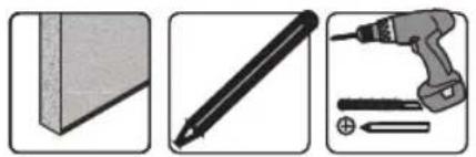
natural_image
Three-panel image showing a pencil, a screwdriver, and a tool (no text or symbols visible)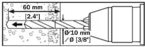
text_image
60 mm [2.4"] Ø/10 mm /Ø [3/8"]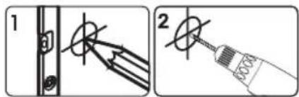
text_image
Technical diagram showing two-step installation of a mechanical component with labeled parts and a close-up of the assembly.text_image
Diagram showing TV lighting symbols with checkmark and cross icons for lighting applicationtext_image
Technical diagram showing three types of TV switch symbols: check, cross, and base, with corresponding icons.text_image
Technical diagram illustrating a mechanical assembly process with labeled components and directional arrows indicating motion or assembly.4. Cuelgue la Pantalla en la Placa de Pared
text_image
Pared Parednatural_image
Technical diagram of a mechanical device with a lever and handle (no text or symbols)natural_image
Circular diagram showing a mechanical lever mechanism with an arrow indicating motion (no text or symbols)natural_image
Technical line drawing of a mechanical frame assembly with mounting brackets and a close-up inset showing a cable (no text or symbols)1111 W. 35th Street, Chicago, IL 60609 EE UU • www.tripplite.com/support
1111 W. 35th Street, Chicago, IL 60609 USA • www.tripplite.com/support
natural_image
Simple line drawing of a long rectangular object with two side protrusions (no text or symbols)Plaque murale verticale (x2)
natural_image
Technical line drawing of a rectangular mechanical component with multiple slots and mounting holes (no text or symbols)Plaque murale horizontale (x2)
natural_image
Simple line drawing of a long rectangular object with a small circular end (no text or symbols)natural_image
Technical line drawing of a mechanical lever assembly (no text or symbols)text_image
Plaque murale verticale Plaque murale horizontale M5 x 8 M5 x 8natural_image
3D diagram of a rectangular frame mounted on a textured wall, no text or symbols present
natural_image
Three-panel image showing a pencil, a screwdriver, and a tool (no text or symbols visible)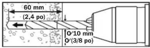
text_image
60 mm (2,4 po) 0/10 mm 0/(3/8 po)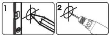
text_image
Technical diagram showing two-step installation of a mechanical component with labeled parts and a magnified view.text_image
Diagram showing TV lighting symbols with checkmark and cross icons for lighting applicationtext_image
Technical diagram showing two types of electrical switch symbols: checkmark and cross symbol with TV labelstext_image
Technical diagram illustrating a mechanical assembly process with labeled components and directional arrows indicating motion or assembly.natural_image
Technical line drawing of a mechanical frame assembly with mounting brackets and a close-up inset showing a connector detail (no text or symbols)1111 W. 35th Street, Chicago, IL 60609 USA • www.tripplite.com/support
1111 W. 35th Street, Chicago, IL 60609 USA - www.tripplite.com/support
natural_image
Simple line drawing of a long rectangular metal rod or support structure (no text or symbols)natural_image
Technical line drawing of a mechanical component with multiple slots and a flat base (no text or symbols)natural_image
Simple line drawing of a long rectangular object with a small circular end (no text or symbols)natural_image
Technical line drawing of a mechanical lever assembly (no text or symbols)text_image
Diagram showing TV lighting symbols with checkmark and cross icons indicating correct and incorrect lighting conditionsnatural_image
Technical line drawing of a mechanical assembly with mounting brackets and a circular component, labeled M6 x 30 M8 (no text or symbols on the diagram itself)

text_image
Diagram showing two types of TV lighting symbols: checkmark and cross, likely indicating different lighting or installation techniques.text_image
Technical diagram illustrating a mechanical assembly process with labeled components and directional arrows indicating motion or assembly.natural_image
Technical line drawing of a mechanical frame assembly with mounting brackets and a close-up inset showing a cable (no text or symbols)1111 W. 35th Street, Chicago, IL 60609 USA • www.tripplite.com/support
Montageanleitung
1111 W. 35th Street, Chicago, IL 60609 USA • www.tripplite.com/support
natural_image
Simple line drawing of a long rectangular object with two side protrusions (no text or symbols)natural_image
Technical line drawing of a rectangular mechanical component with multiple slots and mounting holes (no text or symbols)Horizontale Wandplatte (2 x)
natural_image
Simple line drawing of a long rectangular object with a small circular end (no text or symbols)natural_image
Technical line drawing of a mechanical lever assembly (no text or symbols)Adapterwinkel (x2)

natural_image
3D diagram of a rectangular panel mounted on a textured wall, no text or symbols present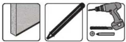
natural_image
Three-panel image showing a pencil, a screwdriver, and a tool (no text or symbols visible)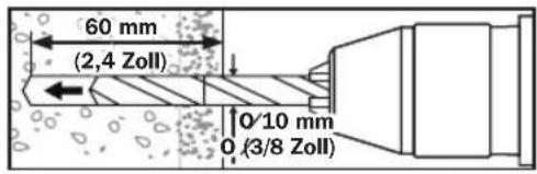
text_image
60 mm (2,4 Zoll) 0/10 mm 0 (3/8 Zoll)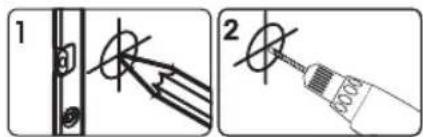
text_image
Technical diagram showing two-step installation of a mechanical component with labeled parts and a close-up of the final assembly.text_image
Diagram showing TV lighting symbols with checkmark and cross icons for lighting applicationtext_image
Technical diagram showing two types of TV (TV) screw fasteners with checkmark and cross symbols indicating inspection or testing conditions.text_image
Technical diagram illustrating a mechanical assembly process with labeled components and directional arrows indicating motion or assembly.natural_image
Technical line drawing of a mechanical frame assembly with mounting brackets and a close-up inset showing a connector detail (no text or symbols)1111 W. 35th Street, Chicago, IL 60609 USA • www.tripplite.com/support