SL100C - Hi-Fi System PANASONIC - Free user manual and instructions
Find the device manual for free SL100C PANASONIC in PDF.

| Product type | Direct drive turntable |
| Brand | Panasonic |
| Model | SL100C |
| Dimensions (W × H × D) | 453 × 169 × 372 mm |
| Weight | Approx. 9.9 kg |
| Power supply | 110 – 240 V AC, 50/60 Hz |
| Power consumption | 8.0 W (On) / 0.2 W (Off) |
| Drive system | Direct drive (brushless DC motor) |
| Rotation speeds | 33⅓ rpm, 45 rpm, 78 rpm |
| Wow and flutter | 0.025 % W.R.M.S. |
| Starting torque | 0.18 N·m |
| Turntable | Die-cast aluminum, diameter 332 mm, mass 2.0 kg (including rubber) |
| Tonearm | Statically balanced type, effective length 230 mm |
| Overhang | 15 mm |
| Tonearm height adjustment range | 0 – 6 mm |
| Stylus pressure adjustment range | 0 – 4 g (direct reading) |
| Included phono cartridge | VM type equivalent to Audio-Technica AT-VM95C |
| Cartridge output voltage | 4.0 mV (1 kHz, 5 cm/s) |
| Recommended stylus pressure | 1.8 – 2.2 g (standard 2.0 g) |
| Headshell weight | Approx. 7.6 g |
| Automatic lift function | Yes (switch on back) |
| Included accessories | Turntable, slip mat, dust cover, 45 rpm adapter, counterweight, headshell with cartridge, PHONO cables, ground cable, power cord |
| Maintenance | Clean stylus with soft brush, wipe terminals, soft cloth for casing |
| Safety | Do not expose to moisture, use supplied accessories, unplug before maintenance |
| Operating temperature | 0 °C to +40 °C |
| Operating humidity | 35 % to 80 % RH (no condensation) |
Frequently Asked Questions - SL100C PANASONIC
User questions about SL100C PANASONIC
0 question about this device. Answer the ones you know or ask your own.
Ask a new question about this device
Download the instructions for your Hi-Fi System in PDF format for free! Find your manual SL100C - PANASONIC and take your electronic device back in hand. On this page are published all the documents necessary for the use of your device. SL100C by PANASONIC.
USER MANUAL SL100C PANASONIC
natural_image
Black Technics 1000 tux tennis paddle with visible branding and control knob (no text or symbols on body)SL-100C
Direct Drive Turntable System
Operating Instructions
Bedienungsanleitung
Mode d'emploi
Music is borderless and timeless, touching people's hearts across cultures and generations.
Each day the discovery of a truly emotive experience from an unencountered sound awaits.
Let us take you on your journey to rediscover music.
Rediscover Music™
Technics
Delivering the Ultimate Emotive Musical Experience to All
At Technics we understand that the listening experience is not purely about technology but the magical and emotional relationship between people and music.
We want people to experience music as it was originally intended and enable them to feel the emotional impact that enthuses and delights them.
Through delivering this experience we want to support the development and enjoyment of the world's many musical cultures. This is our philosophy.
With a combination of our love of music and the vast high-end audio experience of the Technics team, we stand committed to building a brand that provides the ultimate emotive musical experience by music lovers, for music lovers.
Director
Michiko Ogawa

Introduction
Thank you for purchasing this product. Please read these instructions carefully before using this product, and save this manual for future use.
- About descriptions in these operating instructions
- Pages to be referred to are indicated as "(⇒ 00)".
- The illustrations shown may differ from your unit.
Sales and Support Information
Customer Communications Centre
- For customers within the UK: 0333 222 8777
- For customers within Ireland: 01 447 5229
- Monday–Friday 9:00 am – 5:00 pm, (Excluding public holidays).
- For further support on your product, please visit our website: www.technics.com/uk/
Features
Coreless direct drive motor to achieve high precision, stable rotation and high reliability
- Stable rotation is achieved by combining the coreless direct drive motor that reduces minute vibration during rotation with the motor control technology that switches the drive mode depending on the operational status of the motor.
- In addition to providing superior performance, the direct drive motor requires no parts replacement or maintenance.
High-precision bearings for highly sensitive tone arm
- The machine-cut, high-precision bearing used in the tone arm bearing with gimbal suspension allows for high initial response sensitivity and accurate record tracking.
Auto lift-up function to automatically lift up the tone arm - This unit is equipped with an auto lift-up function to automatically lift up the tone arm as a record finishes playing.
Complete package, including the following, to enjoy playing back records
● High-quality VM type cartridge
Table of contents
Before use
Safety precautions 04
Accessories 06
Parts Name 08
Getting started
Putting the player together ....10
- Before fitting the turntable ....11
● Fitting the turntable ....11 - Fitting the turntable mat ....11
- Attaching the head shell ....11
- Attaching the balance weight .....11
- To remove turntable ....11
Connections and installation ....12
- Connecting to an integrated amplifier or component system ....12
- Installation....13
- Fit the dust cover ....13
Adjustment....14
• Horizontal balance .....14
- Stylus pressure ....14
- Anti-skating ....15
- Tone arm height ....16
- Armlift height ....17
Playing back
Playing records 18
Maintenance
Maintenance....20
Replacing the cartridge ....21
Troubleshooting guide 22
Specifications 23
Safety precautions
Warning Caution
Unit
- To reduce the risk of fire, electric shock or product damage,
-Do not expose this unit to rain, moisture, dripping or splashing.
-Do not place objects filled with liquids, such as vases, on this unit.
-Use only the recommended accessories.
-Do not remove covers.
-Do not repair this unit by yourself.
Refer servicing to qualified service personnel.
-Do not let metal objects fall inside this unit.
-Do not place heavy items on this unit.
AC mains lead
- To reduce the risk of fire, electric shock or product damage,
-Ensure that the power supply voltage corresponds to the voltage printed on this unit.
-Insert the mains plug fully into the socket outlet.
-Do not pull, bend, or place heavy items on the lead.
-Do not handle the plug with wet hands.
-Hold onto the mains plug body when disconnecting the plug.
-Do not use a damaged mains plug or socket outlet. - The mains plug is the disconnecting device. Install this unit so that the mains plug can be unplugged from the socket outlet immediately.
- Ensure the earth pin on the mains plug is securely connected to prevent electrical shock.
-An apparatus with CLASS I construction shall be connected to a mains socket outlet with a protective earth connection.
Unit
- Do not place sources of naked flames, such as lighted candles, on this unit.
- This unit may receive radio interference caused by mobile telephones during use. If such interference occurs, please increase separation between this unit and the mobile telephone.
- This unit is intended for use in moderate and tropical climates.
- Do not put any objects on this unit.
This unit becomes hot while it is on.
Placement
- Place this unit on an even surface.
- To reduce the risk of fire, electric shock or product damage,
-Do not install or place this unit in a bookcase, built-in cabinet or in another confined space.
Ensure this unit is well ventilated.
-Do not obstruct this unit's ventilation openings with newspapers, tablecloths, curtains, and similar items.
-Do not expose this unit to direct sunlight, high temperatures, high humidity, and excessive vibration. - Ensure that the placement location is sturdy enough to accommodate the weight of this unit ( 23).
- Do not lift or carry this unit by holding the knobs. Doing so may cause this unit to fall, resulting in personal injury or malfunction of this unit.
- Keep any IC card or magnetic card such as a credit card away from the turntable.
-Otherwise the IC card or magnetic card may become unusable due to the magnetic effect.
Disposal of Old Equipment
Only for European Union and countries with recycling systems
These symbols on the products, packaging, and/or accompanying documents mean that used electrical and electronic products must not be mixed with general household waste.
For proper treatment, recovery and recycling of old products, please take them to applicable collection points in accordance with your national legislation.
By disposing of them correctly, you will help to save valuable resources and prevent any potential negative effects on human health and the environment.
For more information about collection and recycling, please contact your local municipality.
Penalties may be applicable for incorrect disposal of this waste, in accordance with national legislation.
Accessories
In order to prevent damage during shipping some of the equipment has been disassembled. Please check and identify the supplied accessories. (Some accessories parts are supplied in a bag.)
Turntable (1 pc.) (TYL0359) 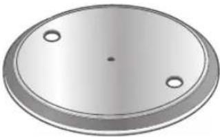 | Turntable mat (1 pc.) (TEFX5019) 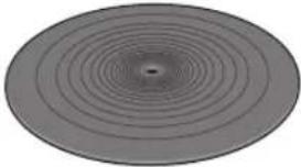 | Dust cover (1 pc.) (TTFA0457)  |
EP record adaptor (1 pc.) (TPH0339)  | Balance weight (1 pc.) (TYL0361) 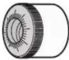 | Head shell with cartridge (1 pc.) (TYL0576) 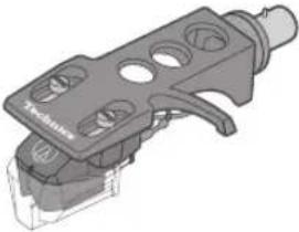 The head shell comes with a cartridge equivalent to "Audio-Technica AT-VM95C". The head shell comes with a cartridge equivalent to "Audio-Technica AT-VM95C". |
PHONO cable (1pc.) PHONO earth lead (1pc.) (TAQ0036) 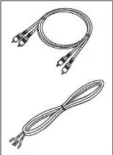 | AC mains lead (1 pc.) (K2CM3YY00055) 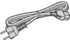 |
- The model numbers of the accessories are as of January 2021.
They are subject to change without notice. - Keep the packaging materials after taking out the goods.
You will need them when carrying the product over long distances. - Follow the local regulations when disposing of the product.
- Do not use any other AC mains lead, PHONO cable and PHONO earth lead except the supplied one.
- Keep the cartridge, nuts, screws and washers out of reach of children to prevent swallowing.
- The stylus is a consumable item. When replacing, purchase Audio-Technica "AT-VMN95C".
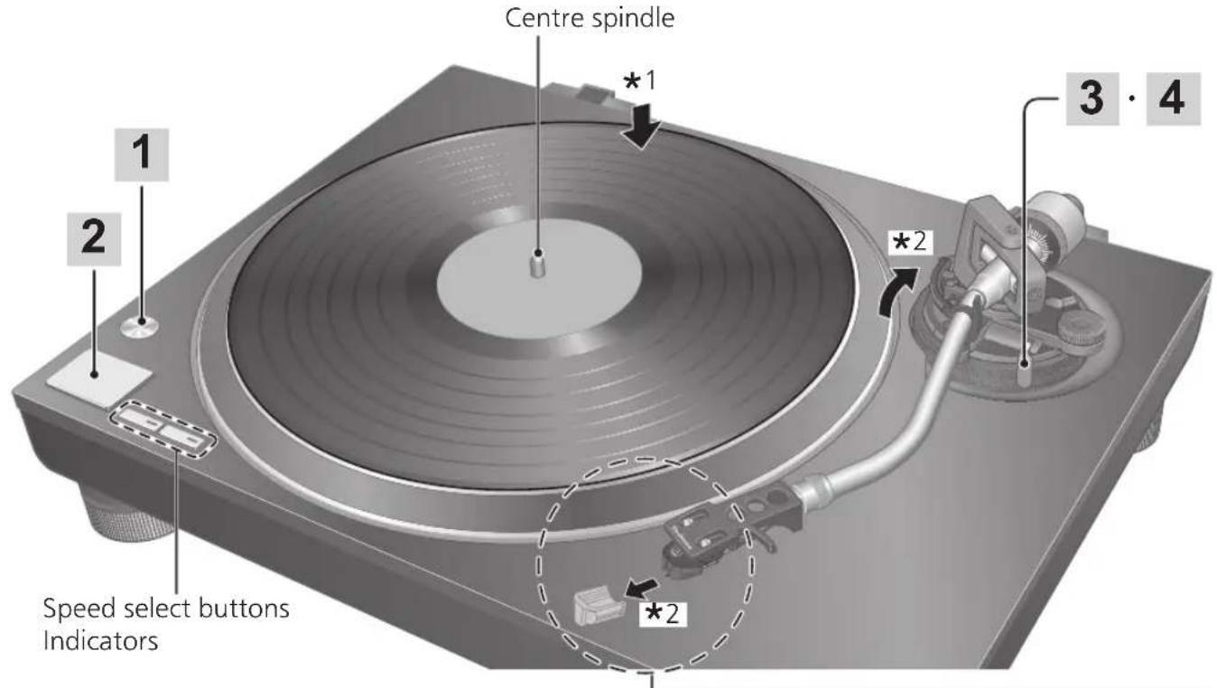
Parts Name
Numbers such as (⇒ 00) indicate reference pages.
Front
![START-STOP button (⇒ 18) ON/OFF (power) [⏻/l] (⇒ 18) Speed select buttons (⇒ 18) Turntable (⇒ 10) Turntable mat (⇒ 10) Centre spindle (⇒ 10) Tone arm (⇒ 14,16) Locking nut (⇒ 11,21) Head shell (⇒ 11,21) Arm clamp (⇒ 14) Arm rest (⇒ 14) Cue lever (⇒ 14,19) Balance weight (⇒ 11) Stylus pressure control (⇒ 14) Arm lock (⇒ 16) Anti-skating control (⇒ 15) Arm-height adjuster (⇒ 16) Cartridge (⇒ 6,18,21) Stylus (⇒ 6,18,21) Insulator (⇒ 13)](/content/2026/03/533693/images/c3f27bbffb98a4809a1323fc13bab9913861c7277f7e2889a1d511b08b8f3ade.jpg)
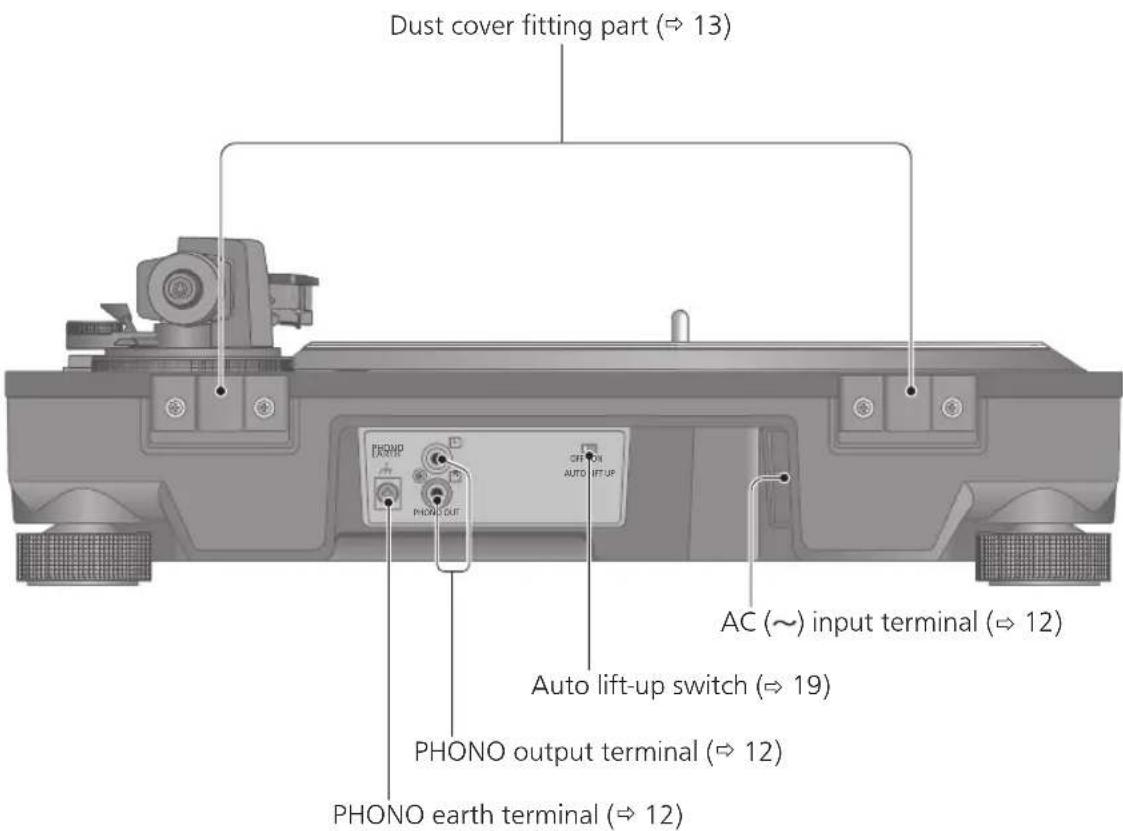
Back
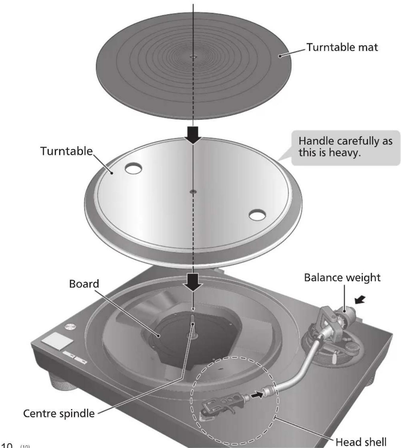
Putting the player together
In order to prevent damage during shipping, some of the equipment has been disassembled. Put the player together in the following order.
Attention
- Before setting up, put on the stylus guard to protect the stylus tip ( 18), return the tone arm to the arm rest and fix it with the arm clamp.
- Do not connect the AC mains lead until set up is complete.
- When fitting the turntable, prevent foreign material from getting in between the main unit and turntable.
- Do not touch or scratch the board.
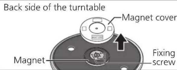
Before fitting the turntable
1 Remove the magnet cover from the turntable.
- There is a magnet and its cover on the back side of the turntable. Remove the magnet cover before fitting to the main unit.
Attention
- Keep any magnetic-sensitive object such as a magnetic card and watch away from the magnet.
- Prevent the turntable from hitting the main unit or falling off.
Prevent dust or iron powder from adhering to the magnet on the back side. - Do not touch the fixing screws (three locations) of the turntable. The rating performance cannot be guaranteed if they are out of position.
Fitting the turntable
2 Slowly set the turntable on the centre spindle.
Attention
- Be careful when handling the turntable, as it is heavy.
- Keep your fingers from being caught.
- Wipe off fingerprints or dirt with a soft cloth.
Fitting the turntable mat
3 Lay the turntable mat on the turntable.
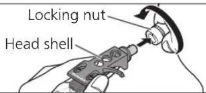
Attaching the head shell
4 Fit the head shell with the cartridge into the tone arm. Keep the head shell horizontal and tighten the locking nut. - Be careful not to touch the stylus tip.
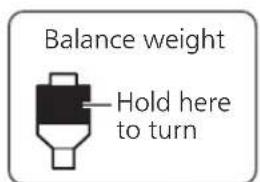
Attaching the balance weight
5 Attach the balance weight to the rear of the tone arm.
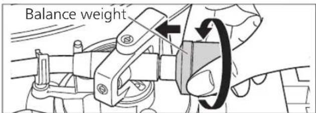
Note
● The inside of the balance weight is greased.
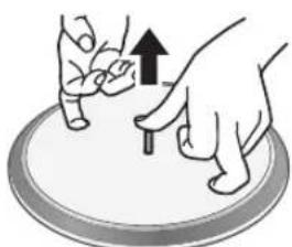
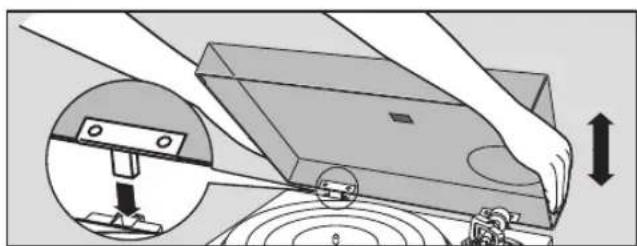
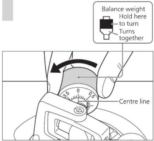
To remove the turntable
As shown in the figure on the right, set your fingers in the two holes on the turntable, hold the centre spindle down and remove the turntable upward.
natural_image
Illustration of hands performing a finger movement on a circular object, with an upward arrow indicating motion (no text or symbols present)Connections and installation
- Turn off all units and disconnect the AC mains lead from the socket before making any connections.
- Connect the AC mains lead only after all other connections are completed.
- Be sure to connect the PHONO earth lead. Otherwise mains hum may occur.
- Refer also to the instruction manual of the connected device.
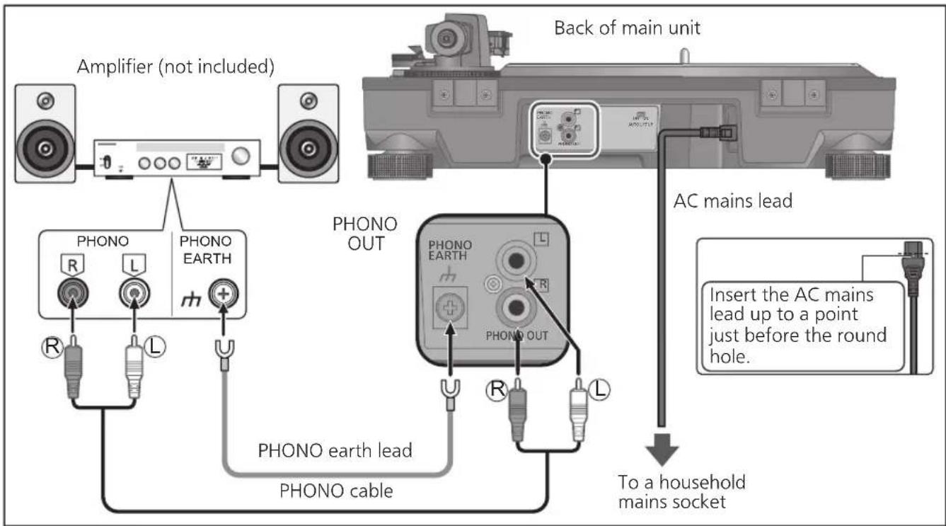
Connecting to an integrated amplifier or component system
1 Turn off the unit and the connected device, and disconnect the AC mains leads from the socket.
2 Connect the PHONO cable and PHONO earth lead to the PHONO input terminals of the connected equipment.
- You will not have adequate volume or sound quality if the connected amplifier has no PHONO input terminals.
3 Connect the AC mains lead.
- Confirm the wattage of the AC outlet on the connected equipment before using it for this unit.
For the power consumption of this unit, see the specifications. ( 23)
Attention
- Tighten the PHONO earth terminal using a Phillips head screwdriver.
Note
- Stanby/on switch [⏻/I] (OFF/ON)
Press to switch the unit from on to standby mode or vice versa.
In standby mode, the unit is still consuming a small amount of power.
Remove the plug from the mains socket if you will not be using the unit for an extended period of time. Place the unit so that the plug can be easily removed.
Installation
Install the unit on a horizontal surface protected from vibrations.
Keep this unit as far as possible from speakers.
■ Adjusting the height to make the unit horizontal
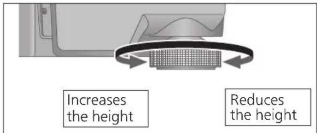
Raise the main unit to turn the insulators and adjust the height.
- Clockwise: Reduces the height.
- Anti-clockwise: Increases the height.
Attention
- Do not turn the insulators too far. Doing so may cause them to come off or damage them.
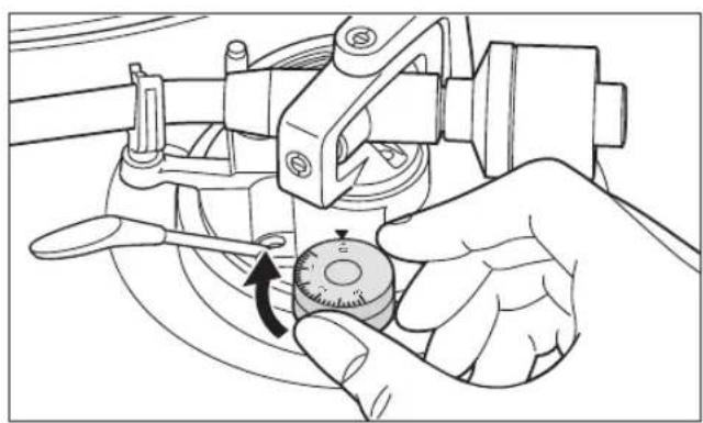
Fit the dust cover
1 Hold the dust cover with both hands and insert it into the dust cover fitting parts ( 9) on the player.
- To remove the dust cover, keep it open and lift it straight above.
natural_image
Diagram showing a hand operating a device with an inset close-up of a mechanical component (no text or symbols)Attention
- Return the tone arm to the arm rest and fix it with the arm clamp before you attach or detach the dust cover.
- Remove the dust cover while playing.
- When inserting the dust cover, prevent the tip of the hinges from hitting and damaging the main unit.
■ Notes for installation
- Before you move the unit, turn the unit off, pull out the power plug and disconnect all connected devices.
- Ensure the unit is not exposed to direct sunlight, dust, humidity, and heat from a heating appliance.
- This unit may pick up interference from a radio if there is one nearby. Keep the unit as far as possible from a radio.
- Do not install the unit on a heat source.
- Avoid a place with large temperature variations.
- Avoid a place with frequent condensation.
- Avoid an unstable place.
- Do not put an object on the unit.
- Do not install the unit in a confined space such as a book shelf.
- Install the unit at a position well away from walls or other devices to ensure effective heat radiation from the inside of the unit.
- Make sure the installation location is sufficiently strong to withstand the total weight of the unit and system.(⇒ 23)
- Note that the unit may be damaged by cigarette smoke or moisture from an ultrasonic humidifier.
Condensation
Think of taking out a cold bottle from a refrigerator. If you leave it in a room for a while, dewdrops will form on the bottle surface. This phenomenon is called "condensation".
- Conditions causing condensation
◇ Rapid temperature change (caused by moving from a warm place to a cold place or vice versa, rapid cooling or heating, or direct exposure to cooled air)
◇ High humidity in a room with much steam, etc.
◇ Rainy season - Condensation may damage the unit. If it has occurred, turn the unit off and leave it until it adapts to the ambient temperature (approximately 2 to 3 hours).
Adjustment
Horizontal balance Stylus pressure
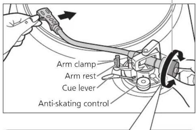
Preparation
- First, remove the dust cover.
- Remove the stylus cover ( 18), taking care not to damage the stylus, then release the arm clamp.
- Lower the cue lever.
- Turn the anti-skating control to "0".
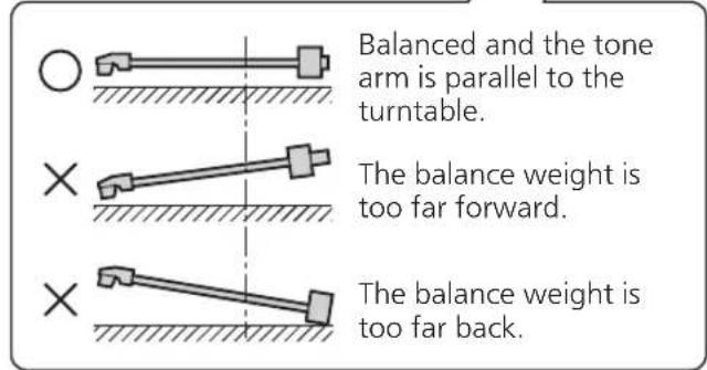
1 Free the tone arm from the arm rest and adjust horizontal balance by turning the balance weight.
Hold the tone arm and turn the balance weight in the arrow direction to adjust the balance until the arm is approximately horizontal.
● Take care not to allow the stylus tip to touch the turntable or main unit.
Preparation
- Return the tone arm to the arm rest and fix it with the arm clamp.
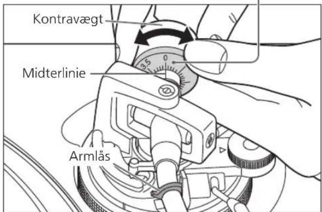
1 Turn the stylus pressure control until "0" comes to the centre line of the rear of the tone arm.
- Hold the balance weight still while doing this.
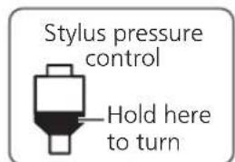

Note
- Stylus pressure of the supplied cartridge: 1.8 to 2.2 g (2.0 g standard)
- When using a separately sold cartridge, refer to the user's guide for your cartridge for the appropriate stylus pressure.
2 Turn the balance weight to adjust to the appropriate stylus pressure for the cartridge.
● The stylus pressure control will turn together with the balance weight.
- Turn until the centre line points to the appropriate stylus pressure.
Anti-skating
1 Turn the anti-skating control to adjust it to the same value as the stylus pressure control.
natural_image
Line drawing of a hand using a mechanical tool to adjust a dial (no text or symbols present)Note
- For stylus pressures 3 g and above, adjust anti-skating control to "3".
Adjustment (continued)
Tone arm height
Make this adjustment only if the cartridge you are using makes it necessary.
Preparation
- Put a record on the turntable.
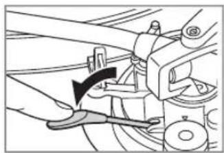
1 Release the arm lock.
Arm lock

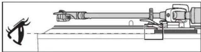
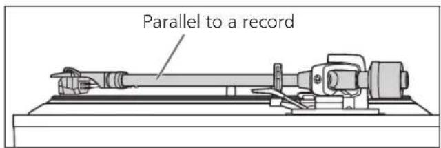
2 Adjust the height with the arm-height adjuster.
Adjust the arm height until the tone arm becomes parallel to the record.
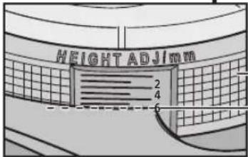
① Use the chart below as reference to find the appropriate position mark for the height of your cartridge.
(When you use the accessory head shell)
| Cartridge height (H) in millimeters | Height control position | |
| 14 | 0 | |
| 15 | 1 | |
| 16 | 2 | |
| 17 | 3 | |
| 18 | 4 | |
| 19 | 5 | |
| 20 | 6 |
● Height of the accessory cartridge H = 17.2 (mm) (Height control position : 3.2)
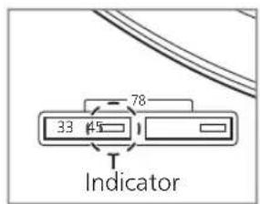
② Hold the arm-height adjuster and slide it up or down to align the position mark with the index line. 0 to 6 mm are marked on the arm height adjuster.
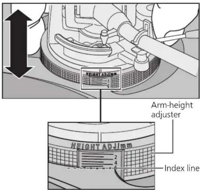
- When checking the index line of the Arm-height adjuster, check with your eyes on the same level.
natural_image
Technical line drawing of a precision optical instrument with a tool and base, showing no text or symbols.- When you don't know the cartridge height (H) or when you don't use the accessory head shell
Remove the stylus cover, taking care not to damage the stylus, then release the arm clamp. Lower the cue lever, rest the stylus on the record and adjust the height control until the tone arm and record are parallel.
- If the cartridge height (H) is too small to make them parallel to each other, add a "cartridge spacer" (not supplied).
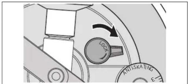
3 After arm height adjustment is finished, lock the tone arm by turning the arm lock knob.
- Be sure to turn the arm lock knob to the end as shown in the figure below. You may need to apply some force to do so.
Attention
- Be careful not to damage the stylus tip.
- Do not use the product with the arm lock released.
- For finer adjustment, use a level (not included) to adjust the arm height so that the cartridge becomes parallel to a record.
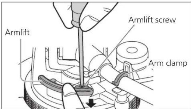
Armlift height
Make an adjustment according to your cartridge if necessary.
Preparation
- Put a record on the turntable.
- Remove the stylus cover ( 18), taking care not to damage the stylus, then release the arm clamp.
- Lift the cue lever and move the tone arm over the record.
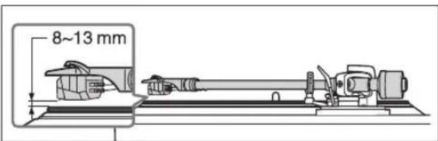
1 Check the armlift height (distance between the stylus tip and record surface).
If adjustment is needed, go to step 2.
● The armlift height is factory-adjusted to 8 to 13 mm.
2 Return the tone arm to the arm rest, clamp it with the arm clamp and while pressing the armlift down with your finger, turn the screw to adjust the height.
- Turning the screw clockwise lowers the armlift.
- Turning the screw anti-clockwise raises the armlift.
Playing records
Preparation
*1 Put a record (not included) on the turntable.
*2 Take off the stylus cover and release the arm clamp.
1 Press [ ] to turn the unit on.
33-1/3 rpm is automatically selected and the indicator [33] lights.
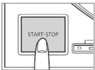
2 Press [START-STOP].
The turntable starts revolving.

Attention
- Do not press [START-STOP] when the turntable is removed.
If you have accidentally pressed [START-STOP]
• The indicator of the speed select button ([33] or [45]) starts blinking.
If it is blinking, press [∅/I] to turn the unit off, fit the turntable and then press [∅/I] turn the unit on.
- Turn the unit on or off with the volume on the connected device set to the minimum.
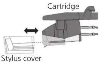
■ Removing the stylus cover
Remove the stylus cover by sliding it straight and slowly in the cartridge front direction while taking care not to damage the stylus.
■ Attaching the stylus cover
Hold the stylus cover firmly from both sides, align with the front of the cartridge, and attach by sliding it slowly while taking care not to damage the stylus.
3 Lift the cue lever and move the tone arm over the record.
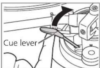
4 Lower the cue lever slowly. The tone arm moves down slowly.
natural_image
Mechanical assembly diagram showing a hand turning a tool on a vehicle wheel (no text or symbols visible)Play starts.
■ To temporarily stop play
Lift the cue lever.
● The stylus lifts off the record.
- To start play again, lower the cue lever.
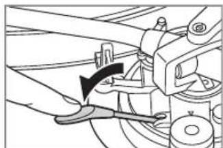
■ When play finishes
① After lifting the cue lever to return the tone arm to the arm rest, lower it completely.
② Press [START-STOP].
The electronic brake gently stops the
turntable.
③ Press [1] to turn the unit off.
④ Clamp the tone arm with the arm clamp.
⑤ Put the stylus cover back on (to protect the stylus tip).
■ Auto lift-up function
This function automatically lifts up the tone arm after a record finishes playing. It prevents the last groove from playing back repeatedly. (It does not stop the turntable rotation.) This function requires the following setting to become active.
Setting: With the unit turned off, set the auto lift-up switch on the rear side to "ON". (The factory setting is "ON".)
- After an auto lift-up, be sure to perform the steps ① to ⑤ described above in "When play finishes".
Attention
- Depending on the record, it may take some time (approximately 60 seconds) after the play finishes for the auto lift-up to operate, or it may operate while the record is still playing. If the tone arm is lifted during play, set the auto lift-up switch to "OFF".
- The auto lift-up function may not operate normally. For the auto lift-up function to operate normally, the cue lever must be completely lowered after the tone arm is returned to the arm rest following the end of play.

■ When playing EP records
- Press the speed select button [45] ([45] lights).
● Fit the EP record adaptor over the centre spindle.
■ When playing SP (78 rpm) records
- Press the speed select buttons [33] and [45] at the same time (78 rpm: [33] and [45] light).
■ When using a record stabilizer (not included)
- See the instruction manual of the record stabilizer.
• Maximum weight: 1 kg
Maintenance
■ Care of the parts
Thoroughly clean dust off the stylus and record.
- Take off the head shell with the cartridge and clean the stylus using a soft brush. Brush from the base to the tip.
- Use a record cleaner to keep your records clean.
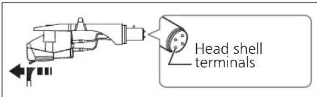
Wipe the head shell terminals occasionally.
Wipe the head shell terminals with a soft cloth and fit the head shell to the tone arm.
Turn the amplifier volume down or turn the amplifier off before fitting or removing the head shell.
Damage to your speakers can occur if the head shell is moved while the volume is turned up.
■ Cleaning the dust cover and cabinet
Wipe the dust cover and cabinet with a soft cloth.
Do not touch the board while cleaning.
Otherwise, the player may fail.
When dirt is heavy, wring a wet cloth tightly to wipe the dirt, and then wipe it with a soft cloth.
- Do not use solvents including benzene, thinner, alcohol, kitchen detergent, a chemical wiper, etc. This might cause the exterior case to be deformed or the coating to come off.
- Do not wipe the dust cover when it is in place. Doing so may cause the tone arm to be attracted towards the dust cover as a result of the generated static electricity. Be sure the dust cover is removed while playing a record.
■ Moving the unit
Repackage the unit in the packaging it came in.
Keep the packaging materials after taking out the goods.
If you no longer have the packaging, do the following:
● Take off the turntable and turntable mat and carefully wrap them.
- Remove the head shell and balance weight from the tone arm and carefully wrap them.
- Clamp the tone arm with the arm clamp and tape it in place.
- Carefully wrap the main unit in a blanket or paper.

WEEE symbol
Disposal of the product outside the EU countries
This symbol is valid within the EU only.
Contact a local governmental office or your dealer to confirm a right manner of disposal.
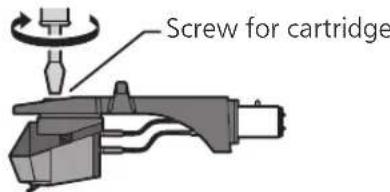
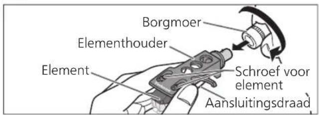
Replacing the cartridge
The cartridge can be replaced with one of your preference.
Removing the supplied cartridge
1 Attach the stylus cover ( 18) and loosen the locking nut to remove the tone arm from the head shell.
2 Loosen the cartridge mounting screws to remove the supplied cartridge from the head shell.
- Use a commercially available mini flat screwdriver (4 mm).
- Be careful not to touch the stylus tip.
3 Remove the leads from the terminals.
- Be careful not to cut the leads.
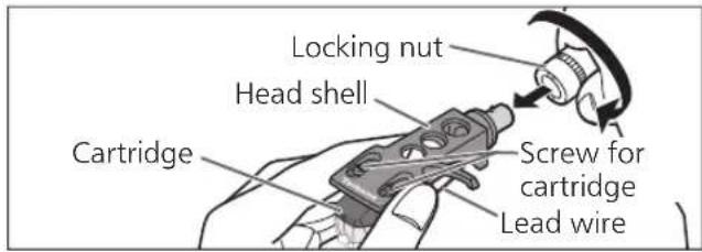
Attaching the cartridge
1 Attach a cartridge tentatively.
Follow the instructions of the replacement cartridge to correctly attach it to the head shell, and tighten the screws lightly.
- If the mounting screws are included in the cartridge, use them.
- When playing SP records, use a cartridge for SP records.
- Use a commercially available mini flat screwdriver (4 mm).
- Be careful not to touch the stylus tip.
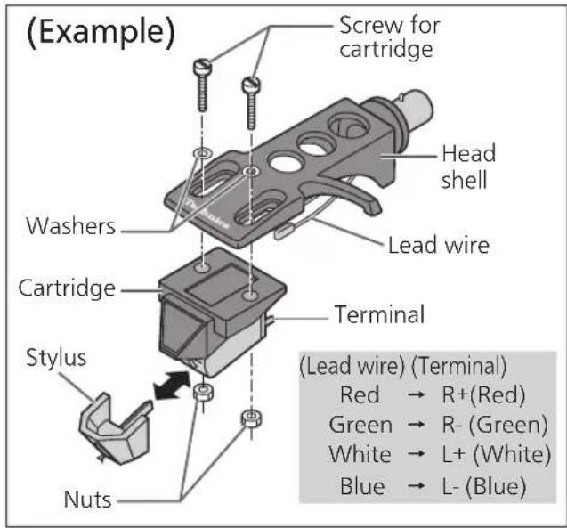
2 Adjust the overhang.
- Be careful not to touch the stylus tip.
① Move the cartridge to adjust the overhang in such a way that the stylus tip is at 52 mm from the head shell mounting end, as shown in the figure below.
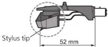
② The cartridge should be parallel on the shell head when viewed from the top and side (the illustration is the top view).

natural_image
Three identical mechanical component diagrams with no text or symbols③ Tighten the screw for cartridge.
- Be careful not to allow the cartridge to slip out of place.
Attaching the head shell
3 Fit the head shell with the cartridge into the tone arm. Keep the head shell horizontal and tighten the locking nut.
- Be careful not to touch the stylus tip.

Attention
- Store the removed screws, washers and nuts in such a way that they do not get lost.
Troubleshooting guide
Before requesting service, make the below checks. If you are in doubt about some of the check points, or if the remedies indicated in the chart do not solve the problem, contact your dealer.
No power.
- Is the AC mains lead plugged in? →Plug the mains lead in firmly. (⇒ 12)
There is power but no sound. Sound is weak.
- Are connections to the amplifier/receiver's PHONO terminals correct? Connect the PHONO cables to the amplifier's PHONO input terminals. ( 12)
Left and right sounds are reversed.
- Are the stereo connection cable connections to the amplifier or receiver reversed? Double check all connections. ( 12)
- Are connections of the head shell's lead wires to the cartridge terminals correct? Double check all connections. ( 21)
Humming is heard during play.
- Are there other appliances or their AC mains lead near the stereo connection cable? Separate the appliances and their AC mains lead from this unit.
- Is the earth lead connected? →Make sure the earth lead is correctly connected. (⇔ 12)
The indicator on the speed select button [33] or [45] blinks.
Perform the following operations when the indicator on the speed select button [33] or [45] blinks. The symptom may be improved.
① Press [1] to OFF.
② Pull out the power plug, wait for three seconds or more, and then insert the plug again.
③ Press [∅to turn the unit on and press [START-STOP] to rotate the turntable.
- If the indicator on the speed select button blinks again, check which one is blinking and contact our service representative.
Specifications
| General | |
| Power supply AC 1 | 10 - 240 V, 50/60 Hz |
| Power consumption | 8.0 W (Power ON)Approx. 0.2 W (Power OFF) |
| Dimensions (W×H×D) | 453 x 169 x 372 mm |
| Mass Approx. 9.9 k | g |
| Operating temperature range | 0 °C to +40 °C |
| Operating humidity range | 35 % to 80 % RH(no condensation) |
| Turntable section | |
| Drive method Direct drive | |
| Motor Brushless DC motor | |
| Turntable platter Aluminum diecastDiameter: 332 mmWeight: About 2.0 kg(including rubber sheet) | |
| Turntable speeds 33- 1/3 rpm, 45 rpm, 78 rpm | |
| Starting torque 0.1 | 8 N·m (1.8 k g·cm) |
| Build-up characteristics | 0.7 s. from standstill to 33-1/3 rpm |
| Braking system Electronic brake | |
| Wow and flutter 0 | 0.025 % W.R.M.S. |
| Tone arm section | |
| Type Static Balance | |
| Effective length 23 | 0 mm |
| Overhang 15 mm | |
| Tracking error angle | Within 2° 32'(at the outer groove of 30 cm record)Within 0° 32'(at the inner groove of 30 cm record) |
| Offset angle 22° | |
| Arm-height adjustment range | 0 - 6 mm |
| Stylus pressure adjustment range | 0 - 4 g (direct reading) |
| Head shell weight | Approx. 7.6 g |
| Applicable cartridge weight range | 5.6 - 12.0 g14.3 - 20.7 g(including the head shell) |
| Shell terminal ø1.2 | mm 4 pin terminal |
| Cartridge section | |
| Type VM type | |
| Output voltage 4.0 | mV (1 kHz, 5 cm/sec.) |
| Mass 6.1 | g |
| Stylus pressure 1.8 | to 2.2 g (2.0 g standard) |
Specifications are subject to change without notice.
Einleitung
natural_image
Illustration of a hand pressing down on a circular object with an upward arrow (no text or symbols)natural_image
Illustration of a hand operating a CD-ROM drive with a magnified inset showing the mechanism (no text or symbols)Achtung
natural_image
Diagram showing three mechanical lever configurations with cross symbols, no text or labels presentnatural_image
Illustration of a hand using a dial indicator to adjust a circular dial (no text or symbols present)Hinweis
natural_image
Technical illustration of a precision cutting machine with a tool and a close-up of the blade (no text or symbols)natural_image
Mechanical assembly diagram showing a hand using a tool to adjust or install a component (no text or symbols visible)natural_image
Exploded view diagram of a mechanical assembly with layered components (no text or symbols)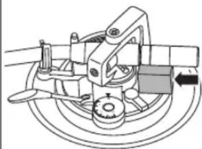
natural_image
Mechanical assembly diagram showing a rotating component with no visible text or symbolsnatural_image
Three identical mechanical component diagrams with circles and crosses, no text or symbols presentnatural_image
Mechanical assembly diagram showing a lever and tool interacting with a mechanical component (no text or symbols visible)Raccordements et installation 12
natural_image
Illustration of a hand pressing down on a circular object with an upward arrow (no text or symbols)Raccordements et installation
natural_image
Diagram showing a hand operating a device with an inset close-up of a mechanical component (no text or symbols)Attention
natural_image
Illustration of a hand using a dial indicator to adjust a mechanical component (no text or symbols present)Remarque
natural_image
Technical line drawing of a precision optical bench with a target and base mount (no text or symbols)natural_image
Mechanical assembly diagram showing a component with arrows indicating direction (no text or symbols)natural_image
Mechanical assembly diagram showing a hand operating a tool with a curved arrow indicating motion (no text or symbols present)La lecture commence.
natural_image
Exploded view diagram of a mechanical assembly with layered components (no text or symbols)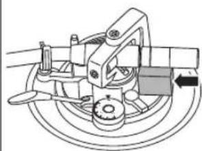
natural_image
Mechanical assembly diagram showing a rotating component with no visible text or symbolsnatural_image
Three identical mechanical component diagrams with no text or symbolsnatural_image
Illustration of a hand pressing down on a circular object with an upward arrow (no text or symbols)natural_image
Illustration of a hand using a device to press or install a box, with an inset showing a close-up of the component (no text or symbols visible)Attenzione
natural_image
Illustration of a hand using a dial indicator to adjust a circular dial (no text or symbols present)Nota
natural_image
Technical illustration of a precision cutting machine with a tool and a small inset image (no text or symbols)natural_image
Mechanical assembly diagram showing a lever mechanism with a curved arrow indicating motion (no text or symbols present)natural_image
Exploded view diagram of a mechanical assembly with layered components (no text or symbols)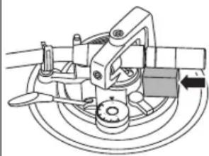
natural_image
Mechanical assembly diagram showing a rotating component with no visible text or symbolsnatural_image
Three mechanical component diagrams showing different assembly states (circles, crosses), no text or symbols present.Nota
- El interior del contrapeso está engrasado.
natural_image
Illustration of two hands performing a finger movement on a circular surface, with an upward arrow indicating motion (no text or symbols)natural_image
Illustration of a hand operating a device with an inset showing a close-up of the component (no text or symbols present)Atención
natural_image
Diagram showing three mechanical linkage configurations with cross symbols, no text or labels presentnatural_image
Illustration of a hand using a dial indicator to adjust a circular dial (no text or symbols present)Nota
natural_image
Technical line drawing of a precision optical instrument with a target reticle and eyepiece (no text or symbols)natural_image
Mechanical assembly diagram showing a hand operating a bracket with a tool, no visible text or symbolsnatural_image
Illustration of a hand pressing down on a circular object with an upward arrow (no text or symbols)Tilslutning og opstilling
natural_image
Diagram showing a hand operating a device with an inset close-up of its components (no text or symbols visible)Bemærk
natural_image
Diagram showing three mechanical linkage configurations with cross symbols, no text or labels presentHold her for at dreje
natural_image
Illustration of a hand using a mechanical tool to adjust a circular component, with an arrow indicating rotation (no text or symbols present)NB
- Ved tryk fra grammofonstift på 3 g eller derover skal du justere knappen for anti-glid til "3".
Armhøjde
natural_image
Technical line drawing of a precision cutting machine with a tool and a separate view of a mechanical component (no text or symbols)4 Sænk pickup-liften langsomt. Tonearmen går langsomt ned.
natural_image
Mechanical assembly diagram showing a lever mechanism with a black arrow indicating motion (no text or symbols present)natural_image
Three identical mechanical or electrical component diagrams with no visible text, numbers, or symbols.natural_image
Illustration of a hand pressing down on a circular object with an upward arrow (no text or symbols)natural_image
Diagram showing a hand operating a device with an inset close-up of the component (no text or symbols)Aandacht
natural_image
Diagram showing three mechanical linkage configurations with cross symbols, no text or labels presentnatural_image
Illustration of a hand using a mechanical device to adjust a circular dial (no text or symbols visible)Opmerking
natural_image
Technical line drawing of a precision optical instrument with a targeting rod and tool, shown alongside a stylized eye symbol (no text or labels)natural_image
Mechanical assembly diagram showing a lever mechanism with no visible text or symbolsnatural_image
Exploded view diagram of a mechanical assembly with layered components (no text or symbols)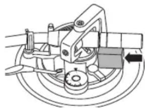
natural_image
Mechanical assembly diagram showing a brake caliper and wheel assembly (no text or labels)3 Remove the leads from the terminals.
- Be careful not to cut the leads.
natural_image
Three mechanical component diagrams showing a shaft, housing, and base with no visible text or symbolsnatural_image
Illustration of a hand pressing down on a circular object with an upward arrow (no text or symbols)natural_image
Diagram showing a hand operating a device with a magnified inset of its components (no text or symbols visible)Observera
natural_image
Diagram showing three mechanical linkage configurations with cross symbols, no text or labels presentnatural_image
Illustration of a hand using a dial indicator to adjust a mechanical component (no text or symbols visible)Notera
natural_image
Technical illustration of a precision optical bench with a tool and mechanical components (no text or symbols)natural_image
Mechanical assembly diagram showing a lever mechanism with no visible text or symbolsnatural_image
Three mechanical component diagrams showing different mounting or positioning configurations (no text or symbols)1LLGHQ PRLWWHHWRQ KIYLWW|PLQHQ DXWWDD VllVW|PllQ DUYRNNDLWD UHVXUVVHMD MD HKN|LVHH LKPLVWHQ YDLNXWWDYLD KDLWWDYDLNXWXNVLD
-RV KDOXDW OLVI WLHWRMD NHU|PLVHVWI MD NLHU|W\NVHVWI RWD \KWH\WWI SDLNDOOLVLLQ YLUDQRPDLVLLI 7|PIQ URPXQ YLUKHHOOLQHQ K|YLWW|PLQHQ YRL MRKWDD UDQJDLVWXVWXRPLRRQ NDQVDOOVLHQ ODLQV|GIQQ|Q
Lisälaitteet
natural_image
Illustration of a hand pressing down on a circular object with an upward arrow (no text or symbols)natural_image
Illustration of a hand pressing down on a device with an inset showing a mechanical component (no text or symbols)Huomio
natural_image
Diagram showing three mechanical linkage configurations with cross symbols, no text or labels presentnatural_image
Illustration of a hand using a dial indicator to adjust a circular dial (no text or symbols present)Huomaa
natural_image
Technical line drawing of a mechanical tool with a tool arm and a separate view of a tool (no text or symbols present)natural_image
Mechanical assembly diagram showing a hand operating a lever with a tool, no text or symbols presentToisto alkaa.
natural_image
Exploded view diagram of a mechanical assembly with layered components (no text or symbols)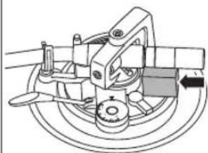
natural_image
Mechanical assembly diagram showing a rotating component with no visible text or symbolsnatural_image
Three mechanical component diagrams showing different mounting or positioning configurations (no text or symbols)natural_image
Illustration of a hand pressing down on a circular object with an upward arrow (no text or symbols)Połączenia i montaż
natural_image
Illustration of a hand holding a device with an inset showing a mechanical component (no text or symbols)Uwaga
natural_image
Diagram showing three mechanical linkage configurations with cross and circle symbols, no text or labels presentnatural_image
Illustration of a hand using a dial indicator to adjust a circular dial (no text or symbols present)Notatka
natural_image
Technical line drawing of a mechanical tool with a hand operating, showing no text or symbols.natural_image
Mechanical assembly diagram showing a tool interacting with a bracket (no text or symbols visible)natural_image
Exploded view diagram of a mechanical assembly with layered components (no text or symbols)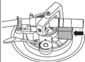
natural_image
Mechanical assembly diagram showing a brake caliper mechanism with no visible text or symbolsnatural_image
Three identical mechanical component diagrams showing a shaft with levers and a circle, plus two cross symbols (no text or labels)Headquarter Address : Panasonic Corporation
1006 Oaza Kadoma, Kadoma City, Osaka 571-8501, Japan
Authorized Representative in Europe : Panasonic Marketing Europe GmbH
Panasonic Testing Centre
Winsbergring 15, 22525 Hamburg, Germany
Producent
Panasonic Corporation
1006 Oaza Kadoma, Kadoma City, Osaka 571-8501, Japonia
CE
Panasonic Corporation
Web Site: http://www.panasonic.com
EnGeFrltSpDuSwDaFiPo

TQBM0768-1
S0121AK2062