CLSuperfly HP Derby - Lighting Cameo - Free user manual and instructions
Find the device manual for free CLSuperfly HP Derby Cameo in PDF.

User questions about CLSuperfly HP Derby Cameo
0 question about this device. Answer the ones you know or ask your own.
Ask a new question about this device
Download the instructions for your Lighting in PDF format for free! Find your manual CLSuperfly HP Derby - Cameo and take your electronic device back in hand. On this page are published all the documents necessary for the use of your device. CLSuperfly HP Derby by Cameo.
USER MANUAL CLSuperfly HP Derby Cameo
natural_image
Exterior view of a cylindrical industrial lamp with grid windows and mounting bracket (no visible text or symbols)5 x 10W DERBY EFFECT
CLSUPERFLYHP
Thank you for choosing this Cameo Light product!
We have designed this product to operate reliably over many years.
Please read this User's Manual carefully, so that you can quickly enjoy all the benefits of your DMX device from Cameo Light.
Learn more about Cameo Light on our website WWW.CAMEOLIGHT.COM.
Introduction
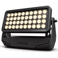
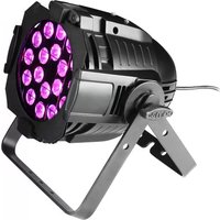
The CLSUPERFLYHP from Cameo Light is an LED Derby effect with 5 x 10 W LEDs. It can be controlled via 5/2 DMX channels, automatically or by music and used as master or slave.
The CLSUPERFLYHP features an easy to read display with function buttons and LEDs for displaying and setting the operating modes, 3-pin DMX input and output sockets, as well as IEC power input and output. The comfortable adjustable bracket and a locking ring allow for reliable assembly of the projector.
5 x 10W DERBY EFFECT
CLSUPERFLYHP

natural_image
Exterior view of a black industrial lamp with grid windows and a handle (no visible text or symbols)PREVENTIVE MEASURES:
- Please read these instructions carefully.
- Keep all information and instructions in a safe place.
- Follow the instructions.
- Observe all safety warnings. Never remove safety warnings or other information from the equipment.
- Use the equipment only in the intended manner and for the intended purpose.
- Use only sufficiently stable and compatible stands and/or mounts (for fixed installations). Make certain that wall mounts are properly installed and secured. Make certain that the equipment is installed securely and cannot fall down.
- During installation, observ e the applicable safety regulations for your country.
- Never install and operate the equipment near radiators, heat registers, ovens or other sources of heat. Make certain that the equipment is always installed so that is cooled sufficiently and cannot overheat.
- Never place sources of ignition, e.g., burning candles, on the equipment.
- Ventilation slits must not be blocked.
- Do not use this equipment in the immediate vicinity of water (does not apply to special outdoor equipment - in this case, observe the special instructions noted below. Do not expose this equipment to flammable materials, fluids or gases.
- Make certain that dripping or splashed water cannot enter the equipment. Do not place containers filled with liquids, such as vases or drinking vessels, on the equipment.
- Make certain that objects cannot fall into the device.
- Use this equipment only with the accessories recommended and intended by the manufacturer.
- Do not open or modify this equipment.
- After connecting the equipment, check all cables in order to prevent damage or accidents, e.g., due to tripping hazards.
- During transport, make certain that the equipment cannot fall down and possibly cause property damage and personal injuries.
- If your equipment is no longer functioning properly, if fluids or objects have gotten inside the equipment or if it has been damaged in anot her way, switch it off immediately and unplug it from the mains outlet (if it is a powered device). This equipment may only be repaired by authorized, qualified personnel.
- Clean the equipment using a dry cloth.
- Comply with all applicable disposal laws in your country. During disposal of packaging, please separate plastic and paper/cardboard.
- Plastic bags must be kept out of reach of children.
FOR EQUIPMENT THAT CONNECTS TO THE POWER MAINS:
-
CAUTION: If the power cord of the device is equipped with an earthing contact, then it must be connected to an outlet with a protective ground. Never deactivate the protective ground of a power cord.
-
If the equipment has been exposed to strong fluctuations in temperature (for example, after transport), do not switch it on immediately. Moisture and condensation could damage the equipment. Do not switch on the equipment until it has reached room temperature.
-
Before connecting the equipment to the power outlet, first verify that the mains voltage and frequency match the values specified on the equipment. If the equipment has a voltage selection switch, connect the equipment to the power outlet only if the equipment values and the mains power values match. If the included power cord or power adapter does not fit in your wall outlet, contact your electrician.
-
Do not step on the power cord. Make certain that the power cable does not become kinked, especially at the mains outlet and/or power adapter and the equipment connector.
-
When connecting the equipment, make certain that the power cord or power adapter is always freely accessible. Always disconnect the equipment from the power supply if the equipment is not in use or if you want
SAFETY:
to clean the equipment. Always unplug the power cord and power adapter from the power outlet at the plug or adapter and not by pulling on the cord. Never touch the power cord and power adapter with wet hands.
-
Whenever possible, avoid switching the equipment on and off in quick succession because otherwise this can shorten the useful life of the equipment.
-
IMPORTANT INFORMATION: Replace fuses only with fuses of the same type and rating. If a fuse blows repeatedly, please contact an authorised service centre.
-
To disconnect the equipment from the power mains completely, unplug the power cord or power adapter from the power outlet.
-
If your device is equipped with a Volex power connector, the mating Volex equipment connector must be unlocked before it can be removed. However, this also means that the equipment can slide and fall down if the power cable is pulled, which can lead to personal injuries and/or other damage. For this reason, always be careful when laying cables.
-
Unplug the power cord and power adapter from the power outlet if there is a risk of a lightning strike or before extended periods of disuse.
CAUTION:
Never remove the cover, because otherwise there may be a risk of electric shock. There are no user serviceable parts inside. Have repairs carried out only by qualified service personnel.
The lightning flash with arrowhead symbol within an equilateral triangle is intended to alert the user to the presence of uninsulated “dangerous voltage” within the product’s enclosure that may be of sufficient magnitude to constitute a risk of electrical shock.
The exclamation mark within an equilateral triangle is intended to alert the user to the presence of important operating and maintenance instructions.
CAUTION! IMPORTANT INFORMATION ABOUT LIGHTING PRODUCTS
- Do not look into the beam from a distance of less than 40 cm.
- Do not stare into the beam for extended periods at short-to-medium distances.
- Do not view the beam directly with optical instruments such as magnifiers.
- Under some circumstances, stroboscopic effects may trigger epileptic seizures in sensitive individuals! For this reason, persons who suffer from epilepsy should always avoid places where strobe lights are used.
The product has been developed for professional use in the field of event technology and is not suitable as household lighting.
INTRODUCTION:
LED EFFECT PROJECTOR
CLSUPERFLYHP
CONTROL FUNCTIONS:
- 5-channel DMX control
• 2-channel DMX control
FEATURES:
- DMX-512 control
• Master / Slave operation - Operating voltage 100 V - 240 V AC
• Power consumption 50 W - Standalone programs
• Music control via built-in microphone - Adjustable mounting bracket included
Derby Effect
- 5 x 10 W LEDs for each RGBW and RGBA
- Rotating reflection mirror
- 24-way lens system
- 150^ beam angle
OPERATION:
The Cameo CLSUPERFLYHP is a DMX-512 controllable effect projector. The Cameo effect projector can be used both individually and in master/slave mode, with music control, and via DMX-512 protocol.
CONNECTIONS, CONTROLS AND INDICATORS:
REAR PANEL
text_image
SAFETY ROPE cameo® colours of light SUPERFLY HP 5 x 10 W RGBAW LED LIGHTING EFFECT ① ② MODE ENTER ↑UP ↓DOWN ③ DMX IN ④ DMX OUT ⑤ POWER IN AC130-240 V 10Hz - 98Hz F 1A L / 250V ⑦ MIC cameo® is a brand of Adam Hall GmbH · Daimlerstraße 9 · 61267 Neu-Anspach · Germany POWER OUT MAX: 8ACONNECTIONS, CONTROLS AND INDICATORS:
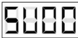
1 LED DISPLAY
The four digit LED display indicates the operating mode and other system information.
2 CONTROL BUTTONS
MODE: Selecting the different operating modes.
ENTER: Confirming program selection and value changes.
UP and DOWN: Selecting a program, changing the program speed and DMX address.
3 DMX IN
3-pin male XLR socket for connection of a DMX controller (e.g., DMX mixer).
4 DMX OUT
3-pin XLR socket for looping through the DMX control signal.
5 POWER IN
IEC power socket with built-in fuse holder. Connection via the included IEC power cord.
IMPORTANT INFORMATION: Replace the fuse only with a fuse of the same type and rating. If the fuse blows repeatedly, please contact an authorised service centre.
6 POWER OUT
IEC mains output socket. Used to supply power to additional CAMEO projectors. Make sure that the total current consumption in amperes (A) of all connected devices does not exceed the specified value on the device.
7 MIC
Microphone for the sound mode.
OPERATION:
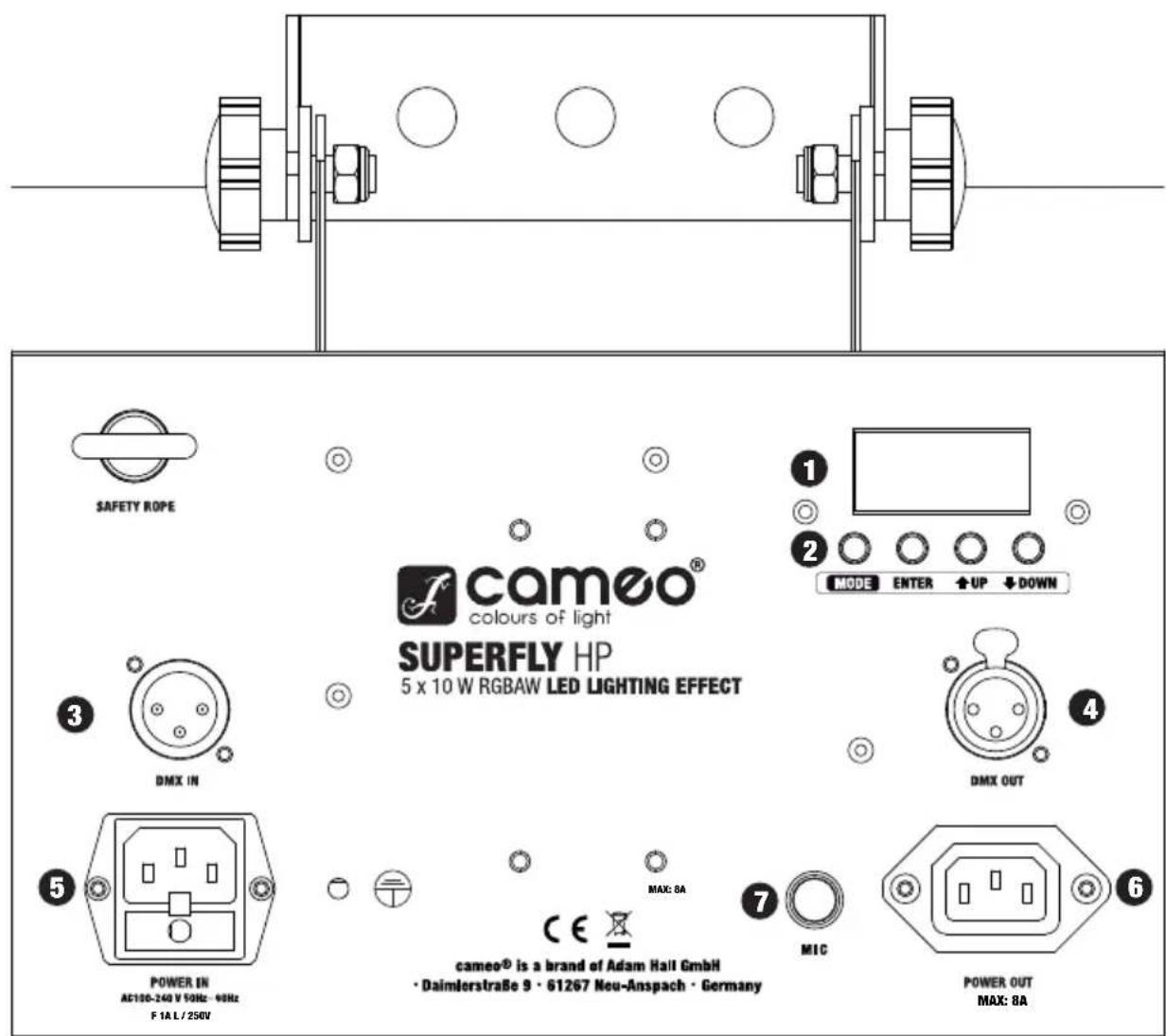
DMX CONTROL AND ADJUSTMENT OF DMX START ADDRESS
Press the MODE button repeatedly until the LED indicator lights up and displays the DMX start address on the display (A001 - A512). The DMX start address can be adjusted as desired by using the UP and DOWN buttons. The synchronous control of several projectors of the same model through a DMX controller (eg DMX console) can be achieved by adjusting the projectors on an identical DMX-starting address and connecting them using DMX cables.
CONVERSION OF THE DMX MODE
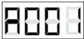
The projector has a 2-channel and 5-channel mode. If you want to switch between these two modes, press the MODE button repeatedly until they reach the address selection (A001-A512). To enter the submenu, select the DMX mode and press the ENTER button. Depending on the operating mode, either "CH02" (2-channel mode) or "CH05" (5-channel mode) will appear on the display. Use the UP and DOWN buttons to select the desired DMX mode.
SLAVE
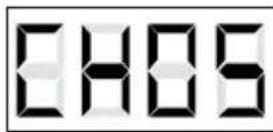
Press the MODE button repeatedly until the LED indicator lights up and displays "SLAV" on the display. Once the slave unit has been connected to the master unit (same model) with the help of a DMX cable (Master = DMX OUT, Slave = DMX IN), and the master unit has been set to one of the standalone modes (automatic control or music control), the slave unit follows the master unit. There is no need for selecting a special setting on the master unit, since the device operates automatically as the Master for both Auto and Music Control modes..
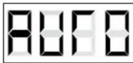
AUTOMATIC CONTROL
Press the MODE button repeatedly until the LED indicator lights up and displays "AUTO" on the display. To change the speed of the automatic mode, press the ENTER button. "SPxx" appears on the display. Using the "UP" and "DOWN" buttons, adjust the speed from "00" to "99".
MUSIC CONTROL
Press the MODE button repeatedly until the LED indicator lights up and displays "SUxx" on the display. Using the UP and DOWN buttons, adjust the sensitivity (SU00 - SU99).
DMX CONTROL:
| 2-CH-MODE | |||
| CHANNEL VALUE FUNCTION | |||
| CH1 | Mode Selection | 000 - 127 | Music control |
| 008 - 015 Auto Mode | |||
| CH2 | Mode Options | 000 - 255 | Sensitivity/ Speed |
| 5-CH-MODE | |||
| CHANNEL VALUE FUNCTION | |||
| CH1032 - 039 Amber | Colour selection | 000 - 007 Red | |
| 008 - 015 Green | |||
| 016 - 023 Blue | |||
| 024 - 031 White | |||
| 040 - 047 Red/ Green | |||
| 048 - 055 Red/ Blue | |||
| 056 - 063 Red/ White | |||
| 064 - 071 Red/ Amber | |||
| 072 - 079 Green/ Blue | |||
| 080 - 087 Green/ White | |||
| 088 - 095 Green/ Amber | |||
| 096 - 103 Blue/ White | |||
| 104 - 111 Blue/ Amber | |||
| 112 - 119 Red/ Green/ Blue | |||
| 120 - 127 | Red/ Green/ White | ||
| 128 - 135 | Red/ Green/ Amber | ||
| 136 - 143 | Red/ Blue/ White | ||
| 144 - 151 | Red/ Blue/ Amber | ||
| 152 - 159 | Red/ White/ Amber | ||
| 160 - 167 | Blue/ White/ Amber | ||
| 168 - 175 | Green/ Blue/ White | ||
| 176 - 183 | Green/ Blue/ Amber | ||
| 184 - 191 | Green/ White/ Amber | ||
| 192 - 199 | Red/ Green/ Blue/ White | ||
| 200 - 207 | Red/ Blue/ White/ Amber | ||
| 208 - 215 | Red/ Green/ White/ Amber | ||
| 216 - 223 | Red/ Green/ Blue/ Amber | ||
| 224 - 231 | Green/ Blue/ White/ Amber | ||
| 232 - 239 | Red/ Green/ White/ Amber | ||
| automatic colour change | 240 - 255 | automatic colour change | |
| CH2 | mirror rotation | 000 - 009 No movement | |
| 010 - 255 slow to fast | |||
| CH3 | Stroboscope | 000 - 001 No strobe | |
| 002 - 255 slow to fast | |||
| CH4 | Dimmer | 000 - 255 0 % to 100 % | |
| CH5 | Colour change speed | 000 - 255 slow to fast | |
DMX CONNECTION:
DMX-512
DMX (Digital Multiplex) is the name of a universal transmission protocol for communication between corresponding devices and controllers. A DMX controller sends DMX data to the connected DMX device(s). The DMX data is always transmitted as a serial data stream that is forwarded from one connected device to the next via the "DMX IN" and "DMX OUT" connectors (XLR plug-type connectors) that are found on every DMX-capable device. (Most controllers only have a DMX output.)
DMX CONNECTION:
DMX is the common "language" via which a very wide range of types and models of equipment from various manufacturers can be connected with one another and controlled via a central controller, provided that all of the devices and the controller are DMX-compatible. For optimum data transmission, it is necessary to keep the connecting cables between the individual devices as short as possible. The order in which the devices are integrated in the DMX network has no influence on addressing. Thus the device with the DMX address 1 can be located at any position in the (serial) DMX chain: at the beginning, at the end or somewhere in the middle. If the DMX address 1 is assigned to a device, the controller "knows" that it should send all data allocated to address 1 to this device regardless of its position in the DMX network.
natural_image
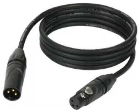
Black cable with two connectors and a connector pin, no visible text or symbolsThe Adam Hall 3 STAR, 4 STAR, and 5 STAR product ranges include an extensive selection of suitable cables.
SERIAL CONNECTION OF MULTIPLE LIGHTS
1.) Connect the male 3-pole XLR connector of the DMX cable to the DMX output (female 3-pole socket) of the first light or other DMX device.
2.) Connect the female 3-pole connector of the DMX cable connected to the first light to the DMX input (male 3-pole socket) of the next DMX device. In like manner, connect the DMX output of this device to the DMX input of the next device and repeat until all devices have been connected.
Please note that as a rule, DMX devices are connected in series and connections cannot be shared without active splitters.
CABLES, TERMINATORS, ADAPTERS:
DMX CABLES:
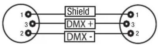
When fabricating your own cables, always observe the illustrations on this page. Never connect the shielding of the cable to the ground contact of the plug, and always make certain that the shielding does not come into contact with the housing of the XLR plug. If the shielding is connected to the ground, this can lead to short-circuiting and system malfunctions.
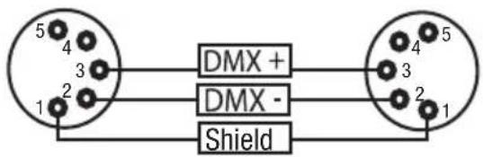
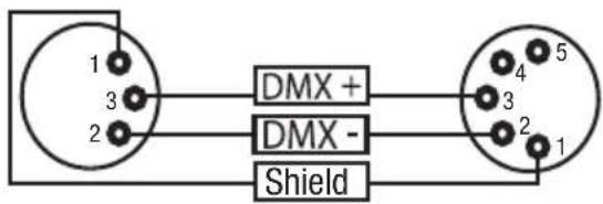
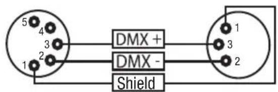
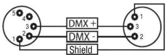
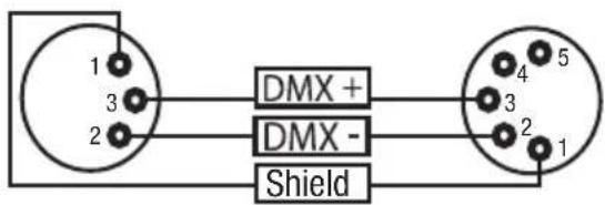
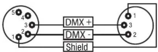
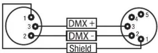
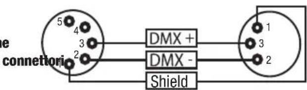
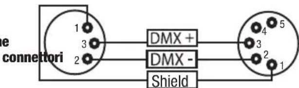
Pin Assignment:
DMX cable with 3-pin XLR connectors:
DMX cable with 5-pin XLR connectors:
flowchart
graph LR
    A["1"] --> B["Shield"]
    C["3"] --> D["DMX +"]
    E["2"] --> F["DMX -"]
    B --> G["1"]
    D --> H["3"]
    F --> I["2"]
text_image
5 4 3 2 1 DMX + DMX - ShieldPins 4 and 5 are not used.
DMX TERMINATORS (TERMINATING RESISTORS):
To prevent system errors, the last device in a DMX chain needs to be equipped with a terminating resistor (120 ohm, 1/4 Watt).
3-pin XLR connector with a terminating resistor: K3DMXT3
5-pin XLR connector with a terminating resistor: K3DMXT5
Pin Assignment:
3-pin XLR connector:
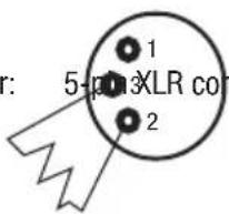
text_image
r: 5-pin XLR con 1 2
text_image
1 2 3 4 5CABLES, TERMINATORS, ADAPTERS:
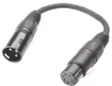
DMX-ADAPTERS:
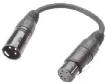
The combination of DMX devices with 3-pin connectors and DMX devices with 5-pin connectors in a DMX chain is possible with suitable adapters.
DMX Adapter 5-pin XLR male to 3-pin XLR female: K3DGF0020

natural_image
Close-up of two black USB connectors with metallic leads, shown in a U-shaped cable (no text or symbols visible)Pin Assignment:
text_image
5 4 3 2 1 DMX + DMX - ShieldPins 4 and 5 are not used.
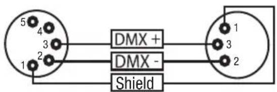
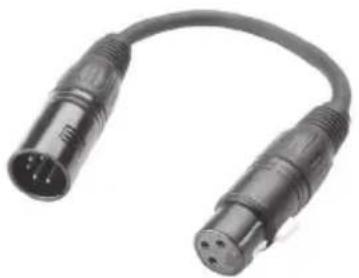
DMX Adapter 3-pin XLR male to 5-pin XLR female: K3DHM0020
natural_image
Close-up of two black USB connectors with metallic leads, no visible text or symbolsPin Assignment:
text_image
1 3 2 DMX + DMX - Shield 4 5 3 2 1Pins 4 and 5 are not used.
SPECIFICATIONS:
| Model Name: CLSUPERFLYHP | |
| Product Type: LED Derby effect | |
| Type: effect projector | |
| Colour Spectrum RGBWA | |
| Number of LEDs 5 | |
| LED Type: 10 W LED | |
| Beam Angle: 150° | |
| DMX Input 3-pin XLR male | |
| DMX Output 3-pin XLR female | |
| DMX Mode: 5-channel, 2-channel | |
| DMX Functions: Auto program, Music Control, Rotation Speed, Colour, Dimmer, Strobe | |
| Standalone Functions: Auto program, Music Control, | |
| Controls MODE, ENTER, UP, DOWN buttons | |
| Indicators 4-digit LED display | |
| Power Connector: | IEC power input and output |
| Operating Voltage | 100 V-240 V AV / 50-60 Hz |
| Power Consumption | 50 W |
| Fuse | F 1A L / 250 V |
| Operating Temperature: | 45 °C |
| Relative Humidity: | 85% |
| Housing Material | metal |
| Housing Colour: | black |
| Dimensions (W x H x D, excluding bracket): | 360 mm x 225 mm x 300 mm |
| Weight | 6.1 kg |
| Other Features | adjustable mounting bracket included |
MANUFACTURER'S DECLARATIONS:
MANUFACTURER'S WARRANTY
This warranty extends to the CAMEO branded product you purchased from Adam Hall. The statutory warranty rights against the vendor shall not be affected by this warranty. Rather, this warranty gives you additional independent claims against Adam Hall.
With this warranty, Adam Hall ensures that products you have purchased from Adam Hall or Adam Hall partners, under normal use, are free of defects in material or workmanship for a period of 2 years from the date of purchase. The warranty period begins on the date of purchase. In order to assert a claim for warranty service, the proof of date of purchase is provided by the receipt bearing the date of purchase or the date of purchase on the delivery note. You are entitled to warranty service under the conditions and provisions set out in this document, if a repair within the warranty period is required.
This warranty applies only to the original purchaser of the products supplied by Adam Hall and is not transferable to any person to whom the property is transferred by the original purchaser.
Within the warranty period, the defective parts or the product from Adam Hall will be repaired or replaced. Under the terms of this warranty, all the replaced or removed components become the property of Adam Hall.
In the unlikely event that a product acquired from Adam Hall, repeatedly exhibits a defect, Adam Hall may decide, at its discretion, to replace this product with a comparable product of at least the same performance.
Adam Hall does not guarantee that the operation of this product will be uninterrupted or error-free. Adam Hall accepts no responsibility for any damage due to incorrect compliance with the instructions received in the delivery.
This warranty does not extend to:
- wearing parts (eg battery, tubes).
- devices that have had their serial number removed or damaged, or failed as a result of an accident
- inappropriate or abusive use or other external causes
- devices that were not used in accordance with the operating parameters defined in the user documentation shipped with the product
- devices that have been repaired using parts not made or distributed by Adam Hall
- devices that have been serviced, modified or repaired by someone other than Adam Hall or an authorised service partner.
These terms and conditions constitute the complete and exclusive warranty agreement between you and Adam Hall regarding the Adam Hall branded product you have purchased.
This warranty is valid only within Europe. Outside of Europe please contact our official distributors.
MANUFACTURER'S DECLARATIONS:
LIMITATION OF LIABILITY
If your Adam Hall branded hardware product fails to work as warranted above, your sole and exclusive remedy shall be repair or replacement. Adam Halls' maximum liability under this limited warranty is expressly limited to the lesser of the price you have paid for the product or the cost of repair or replacement of any components that malfunction under conditions of normal use.
Adam Hall is not liable for any damages caused by the product or the failure of the product, including any lost profits or savings or special, incidental, or consequential damages. Adam Hall is not liable for any claim made by a third party or made by you for a third party.
This limitation of liability applies whether damages are sought, or claims are made, under this Limited Warranty or as a tort claim (including negligence and strict product liability), a contract claim, or any other claim, and cannot be rescinded or changed by anyone. This limitation of liability will be effective even if you have advised Adam Hall or an authorized representative of Adam Hall of the possibility of any such damages, but not, however, in the event of claims for damages in connection with personal injuries.
This manufacturer's warranty grants you specific rights; depending on jurisdiction (nation or state), you may be entitled to additional claims. You are advised to consult applicable state or national laws for a full determination of your rights.
REQUESTING WARRANTY SERVICE
To request warranty service for the product, contact Adam Hall or the Adam Hall authorized reseller from which you purchased the product.
EC DECLARATION OF CONFORMITY
The equipment marketed by Adam Hall complies (where applicable) with the essential requirements and other relevant specifications of Directives 1999/5/EC (R&TTE), 2004/108/EC (EMC) und 2006/95/EC (LVD). Additional information can be found at www.adamhall.com.
MANUFACTURER'S DECLARATIONS:
PROPER DISPOSAL OF THIS PRODUCT
(Valid in the European Union and other European countries with waste separation)

This symbol on the product, or the documents accompanying the product, indicates that this appliance may not be treated as household waste. This is to avoid environmental damage or personal injury due to uncontrolled waste disposal. Please dispose of this product separately from other waste and have it recycled to promote sustainable economic activity.
Household users should contact either the retailer where they purchased this product, or their local government office, for details on where and how they can recycle this item in an environmentally friendly manner. Business users should contact their supplier and check the terms and conditions of the purchase contract. This product should not be mixed with other commercial wastes for disposal.
ENVIRONMENTAL PROTECTION AND ENERGY CONSERVATION
Energy conservation is an active contribution to environmental protection. Please turn off all unneeded electrical devices. To prevent unneeded devices from consuming power in standby mode, disconnect the mains plug.
Adam Hall GmbH, all rights reserved. The technical data and the functional product characteristics can be subject to modifications. The photocopying, the translation, and all other forms of copying of fragments or of the integrity of this user's manual is prohibited.
natural_image
Exterior view of a black industrial lamp with grid windows and a handle (no visible text or symbols)natural_image
Coiled black electrical connector with two connectors and a 3-pin connector (no text or symbols visible)DMX-Adapter 5-Pol XLR male auf 3-Pol XLR female: K3DGF0020
natural_image
Close-up of two black USB connectors with metallic leads, shown in a U-shaped bundle (no text or symbols visible)Steckerbelegung
text_image
5 4 3 2 1 DMX + DMX - Shield 1 3 2natural_image
Close-up of two black audio/video connectors with metallic leads and a curved cable (no text or symbols visible)Steckerbelegung

text_image
1 3 2 DMX + DMX - Shield 4 5 3 2 1natural_image
Exterior view of a black industrial lampshade with grid windows and mounting bracket (no text or symbols visible)MESURES PRÉVENTIVES:
natural_image
Black cable with two connectors and a connector, no visible text or symbolsCONNEXION EN SÉRIE DE PLUSIEURS PROJECTEURS
natural_image
Close-up of two black USB connectors with metallic pins, no visible text or symbolsAssignation des points
text_image
5 4 3 2 1 DMX + DMX - Shieldnatural_image
Close-up of a black audio/video audio connector with two leads (no text or symbols visible)Assignation des contacts
text_image
1 3 2 DMX + DMX - ShieldDÉCLARATION DE CONFORMITÉ CE
MISE AU REBUT DE CE PRODUIT
natural_image
Exterior view of a black industrial lamp with grid windows and a handle (no visible text or symbols)natural_image
Black cable with two connectors and a connector pin, no visible text or symbolstext_image
1 3 2 Connector XLR a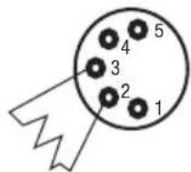
text_image
1 2 3 4 5natural_image
Close-up of two black USB connectors with metallic pins, shown in a U-shaped bundle (no text or symbols visible)Asignación de pines
text_image
5 4 3 2 1 DMX + DMX - ShieldLos pines 4 y 5 no se utilizan.
Adaptador DMX de XLR macho 3 pines a XLR hembra 5 pines: K3DHM0020
natural_image
Close-up of a black audio/video audio connector with two leads (no text or symbols visible)Asignación de pines
text_image
1 3 2 DMX + DMX - ShieldLos pines 4 y 5 no se utilizan.
CARACTERÍSTICAS TÉCNICAS:
natural_image
Exterior view of a black industrial lamp with grid windows and a handle (no visible text or symbols)ŚRODKI OSTROŻNOŚCI:
natural_image
Coiled black electrical connector with two connectors and a terminal pin (no text or symbols visible)POŁĄCZENIE SZEREGOWE KILKU REFLEKTORÓW
natural_image
Close-up of two black USB connectors with three pins, shown in a U-shaped bundle (no text or symbols visible)natural_image
Close-up of a black USB cable with two metallic connectors (no text or symbols visible)GWARANCJA PRODUCENTA
DEKLARACJA ZGODNOŚCI WE
natural_image
Exterior view of a black industrial lamp with grid windows and a handle (no visible text or symbols)MISURE PRECAUZIONALI:
natural_image
Black cable with two connectors and three gold pins, no visible text or symbolsnatural_image
Close-up of a black USB cable with two metallic connectors (no text or symbols visible)Configurazione dei
text_image
e connettori 5 4 3 2 DMX + DMX - Shield 1 3 2natural_image
Close-up of a black audio/video audio connector with two leads (no text or symbols visible)Configurazione dei
text_image
e connettori 1 3 2 DMX + DMX - Shieldnatural_image
Stylized white letter 'J' on black background, enclosed in a rounded square frame (no text or symbols)WWW.CAMEOLIGHT.COM