
IPR2 7500 - Receiver PEAVEY - Free user manual and instructions
Find the device manual for free IPR2 7500 PEAVEY in PDF.

| Brand | PEAVEY |
| Model | IPR2 7500 |
| Product type | Stereo power amplifier |
| Technology | Class D with resonant switching power supply |
| Output power (2 ohms) | 4750 W burst, 3750 W at 1% THD (both channels) |
| Output power (4 ohms) | 2800 W burst, 2450 W at 1% THD, 2020 W at 0.15% THD |
| Output power (8 ohms) | 1550 W burst, 1425 W at 1% THD, 1200 W at 0.15% THD |
| Frequency response | 20 Hz - 25 kHz (+0 / -3 dB) |
| Harmonic distortion | <0.5% at 2 ohms, <0.15% at 4 and 8 ohms (20 Hz - 20 kHz) |
| Inputs | 2 x combo XLR + 6.35 mm jack (isolated) |
| Outputs | 2 x 4-pole locking connectors (per channel) + 2 x direct 6.35 mm jack |
| LED indicators per channel | Active, Signal, DDT, Temperature, DC |
| Integrated protection | Thermal, DC, subsonic, over/under voltage, short-circuit |
| Cooling | 3 variable speed fans |
| Integrated filters | 2nd order high-pass and 3rd order low-pass at 100 Hz switchable per channel |
| DDT function | Distortion detection and reduction to protect speakers |
| Power supply | 120-240 V AC, 50/60 Hz (depending on model) |
| Idle consumption | 250 VA (120 W) |
| Dimensions (H x W x D) | 8.9 x 48.3 x 43.2 cm (without handle) + 1.5 cm handle |
| Net weight | 6.61 kg |
| Gross weight | 8.34 kg |
| Chassis | Aluminum, thickness 0.15 mm |
Frequently Asked Questions - IPR2 7500 PEAVEY
User questions about IPR2 7500 PEAVEY
0 question about this device. Answer the ones you know or ask your own.
Ask a new question about this device
Download the instructions for your Receiver in PDF format for free! Find your manual IPR2 7500 - PEAVEY and take your electronic device back in hand. On this page are published all the documents necessary for the use of your device. IPR2 7500 by PEAVEY.
USER MANUAL IPR2 7500 PEAVEY
www.peavey.com

Intended to alert the user to the presence of uninsulated “dangerous voltage” within the product’s enclosure that may be of sufficient magnitude to constitute a risk of electric shock to persons.
Intended to alert the user of the presence of important operating and maintenance (servicing) instructions in the literature accompanying the product.
CAUTION: Risk of electrical shock — DO NOT OPEN!
CAUTION: To reduce the risk of electric shock, do not remove cover. No user serviceable parts inside. Refer servicing to qualified service personnel.
WARNING: To prevent electrical shock or fire hazard, this apparatus should not be exposed to rain or moisture, and objects filled with liquids, such as vases, should not be placed on this apparatus. Before using this apparatus, read the operating guide for further warnings.

Protective earthing terminal. The apparatus should be connected to a mains socket outlet with a protective earthing connection.

IMPORTANT SAFETY INSTRUCTIONS
WARNING: When using electrical products, basic cautions should always be followed, including the following:
- Read these instructions.
- Keep these instructions.
- Heed all warnings.
- Follow all instructions.
- Do not use this apparatus near water.
- Clean only with a dry cloth.
-
Do not block any of the ventilation openings. Install in accordance with manufacturer's instructions.
-
Do not install near any heat sources such as radiators, heat registers, stoves or other apparatus (including amplifiers) that produce heat.
- Do not defeat the safety purpose of the polarized or grounding-type plug. A polarized plug has two blades with one wider than the other. A grounding type plug has two blades and a third grounding plug. The wide blade or third prong is provided for your safety. If the provided plug does not fit into your outlet, consult an electrician for replacement of the obsolete outlet.
-
Protect the power cord from being walked on or pinched, particularly at plugs, convenience receptacles, and the point they exit from the apparatus.
-
Only use attachments/accessories provided by the manufacturer.
-
Use only with a cart, stand, tripod, bracket, or table specified by the manufacturer, or sold with the apparatus. When a cart is used, use caution when moving the cart/apparatus combination to avoid injury from tip-over.
-
Unplug this apparatus during lightning storms or when unused for long periods of time.
-
Refer all servicing to qualified service personnel. Servicing is required when the apparatus has been damaged in any way, such as power-supply cord or plug is damaged, liquid has been spilled or objects have fallen into the apparatus, the apparatus has been exposed to rain or moisture, does not operate normally, or has been dropped.
-
Never break off the ground pin. Write for our free booklet "Shock Hazard and Grounding." Connect only to a power supply of the type marked on the unit adjacent to the power supply cord.
-
If this product is to be mounted in an equipment rack, rear support should be provided.
-
Note for UK only: If the colors of the wires in the mains lead of this unit do not correspond with the terminals in your plug, proceed as follows: a) The wire that is colored green and yellow must be connected to the terminal that is marked by the letter E, the earth symbol, colored green or colored green and yellow. b) The wire that is colored blue must be connected to the terminal that is marked with the letter N or the color black. c) The wire that is colored brown must be connected to the terminal that is marked with the letter L or the color red.
-
This electrical apparatus should not be exposed to dripping or splashing and care should be taken not to place objects containing liquids, such as vases, upon the apparatus.
-
The on/off switch in this unit does not break both sides of the primary mains. Hazardous energy can be present inside the chassis when the on/off switch is in the off position. The mains plug or appliance coupler is used as the disconnect device, the disconnect device shall remain readily operable.
-
Exposure to extremely high noise levels may cause a permanent hearing loss. Individuals vary considerably in susceptibility to noise-induced hearing loss, but nearly everyone will lose some hearing if exposed to sufficiently intense noise for a sufficient time. The U.S. Government's Occupational Safety and Health Administration (OSHA) has specified the following permissible noise level exposures:
Duration Per Day In Hours Sound Level dBA, Slow Response
| 8 90 | |
| 6 92 | |
| 4 95 | |
| 3 97 | |
| 2 100 | |
| 1 1/2 102 | |
| 1 105 | |
| 1/2 | 110 |
| 1/4 or less | |
According to OSHA, any exposure in excess of the above permissible limits could result in some hearing loss. Earplugs or protectors to the ear canals or over the ears must be worn when operating this amplification system in order to prevent a permanent hearing loss, if exposure is in excess of the limits as set forth above. To ensure against potentially dangerous exposure to high sound pressure levels, it is recommended that all persons exposed to equipment capable of producing high sound pressure levels such as this amplification system be protected by hearing protectors while this unit is in operation.
SAVE THESE INSTRUCTIONS!
a) The wire that is colored green and yellow must be connected to the terminal that is marked by the letter E, the earth symbol, colored green or colored green and yellow.
b) The wire that is colored blue must be connected to the terminal that is marked with the letter N or the color black.
c) The wire that is colored brown must be connected to the terminal that is marked with the letter L or the color red.
a) The wire that is colored green and yellow must be connected to the terminal that is marked by the letter E, the earth symbol, colored green or colored green and yellow.
b) The wire that is colored blue must be connected to the terminal that is marked with the letter N or the color black.
Logo referenced in Directive 2002/96/EC Annex IV(OJ(L)37/38,13.02.03 and defined in EN 50419: 2005
The bar is the symbol for marking of new waste and is applied only to equipment manufactured after 13 August 2005
Correct Disposal of this product. This marking indicates that this product should not be disposed with other house hold wastes throughout the EU. To prevent possible harm to the environment or human health from uncontrolled waste disposal, recycle it responsibly to promote the sustainable reuse of material resources. To return your used device, please use the return and collection systems, or contact the retailer where the product was purchased. They can take this product for environmental safe recycling.

FCC Compliancy Statement
This equipment has been tested and found to comply with the limits for a Class A digital device, pursuant to Part 15 of the FCC rules. These limits are designed to provide reasonable protection against harmful interference when the equipment is operated in a commercial environment. This equipment generates, uses and can radiate radio frequency energy and, if not installed and used in accordance with the instruction manual, may cause harmful interference to radio communications. Operation of this equipment in a residential area is likely to cause harmful interference in which case the user will be required to correct the interference at his own expense.
Warning: Changes or modifications to the equipment not approved by Peavey Electronics Corp. can void the user's authority to use the equipment.

Peavey Electronics Corporation • 5022 Hartley Peavey Drive • Meridian, MS • 39305
(601) 483-5365 • FAX (601) 486-1278 • www.peavey.com • 80305796 • ©2011
CAN ICES-3 B/NMB/3B
ENGLISH
IPR2™ 5000 / 7500
Power Amplifier
Congratulations on your purchase of an IPR2™ power amplifier, designed for years of reliable, flawless operation under rigorous use. The groundbreaking IPR series utilizes an advanced design that allows Peavey engineers to dramatically reduce weight while increasing output power, reliability and thermal efficiency. IPR Series amplifiers are designed with a resonant switch-mode power supply and a high-speed class D topology that yields the highest audio resolution and efficiency available. This revolutionary amplifier offers the sonic superiority and unsurpassed reliability for which Peavey is famous, in an extremely efficient and lightweight design. Advanced technology and extensive protection circuitry allow operation with greater efficiency into difficult loads and power conditions. The DDT™ (Distortion Detection Technique) circuitry ensures trouble-free operation into loads as low as 2 ohms. DDT protects drivers and ensures that sonic integrity is maintained, even in extreme overload conditions. The IPR's high-efficiency design allows the amplifier to operate at very low temperatures, and does not require massive heat sinks to cool. For your safety, read the important precautions section, as well as input, output and power connection instructions.
Although the IPR amplifier is simple to operate and housed in an ultra-strong, ultra-lightweight chassis, improper use can be dangerous. This amplifier is very high-powered and can put out high voltages and sizable currents at frequencies up to 30 kHz. Always use safe operating techniques when operating this amplifier.
Before you send signal through your amplifier, it is very important to ensure that the product has the proper AC line voltage supplied. You can find the proper voltage for your amp printed next to the IEC line (power) cord on the rear panel of the unit. Each product feature is numbered. Refer to the front-panel diagram in this manual to locate the particular features next to its number.

Please read this guide carefully to ensure your personal safety as well as the safety of your amplifier.
FEATURES:
• 2 channel independent crossovers
- DDT protection
• Revolutionary IPR class D topology
• Detented input controls
- Combination XLR 1/4" inputs
• 4 pole twist lock output connectors
- Ultra-light weight
- Individual signal pass 1/4" jacks on each channel
- LED illuminated
- Standby, LED power present indication

VENTILATION: For proper ventilation, allow 12" clearance from nearest combustible surface.
Make sure that vents are not blocked and air can flow freely through the unit.

WARNING: Changes or modifications to this unit not expressly approved by the party responsible for compliance could void the user's authority to operate the equipment.
NOTE: This equipment has been tested and found to comply with the limits for a Class A digital device, pursuant to Part 15 of the FCC Rules. These limits are designed to provide reasonable protection against harmful interference in a residential installation. This equipment generates, uses and can radiate radio frequency energy and if not installed and used in accordance with the instructions, may cause harmful interference to radio communications.
However, there is no guarantee that interference will not occur in a particular installation. If this equipment does cause harmful interference to radio or television reception, which can be determined by turning the equipment off and on, the user is encouraged to try to correct the interference by one or more of the following measures:
- Reorient or relocate the receiving antenna.
- Increase the separation between the equipment and receiver.
- Connect the equipment into an outlet on a circuit different from that to which the receiver is connected.
- Consult the dealer or and experienced radio/TV technician for help.
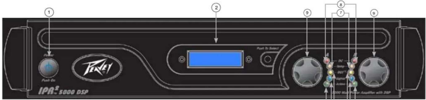
Front Panel
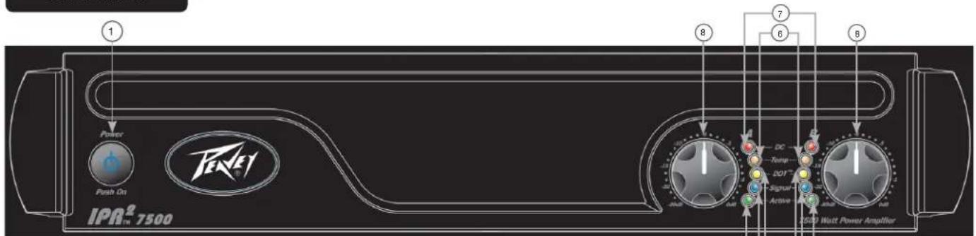
IPR2™ 7500
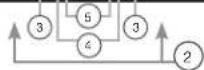
IPR2™ 5000
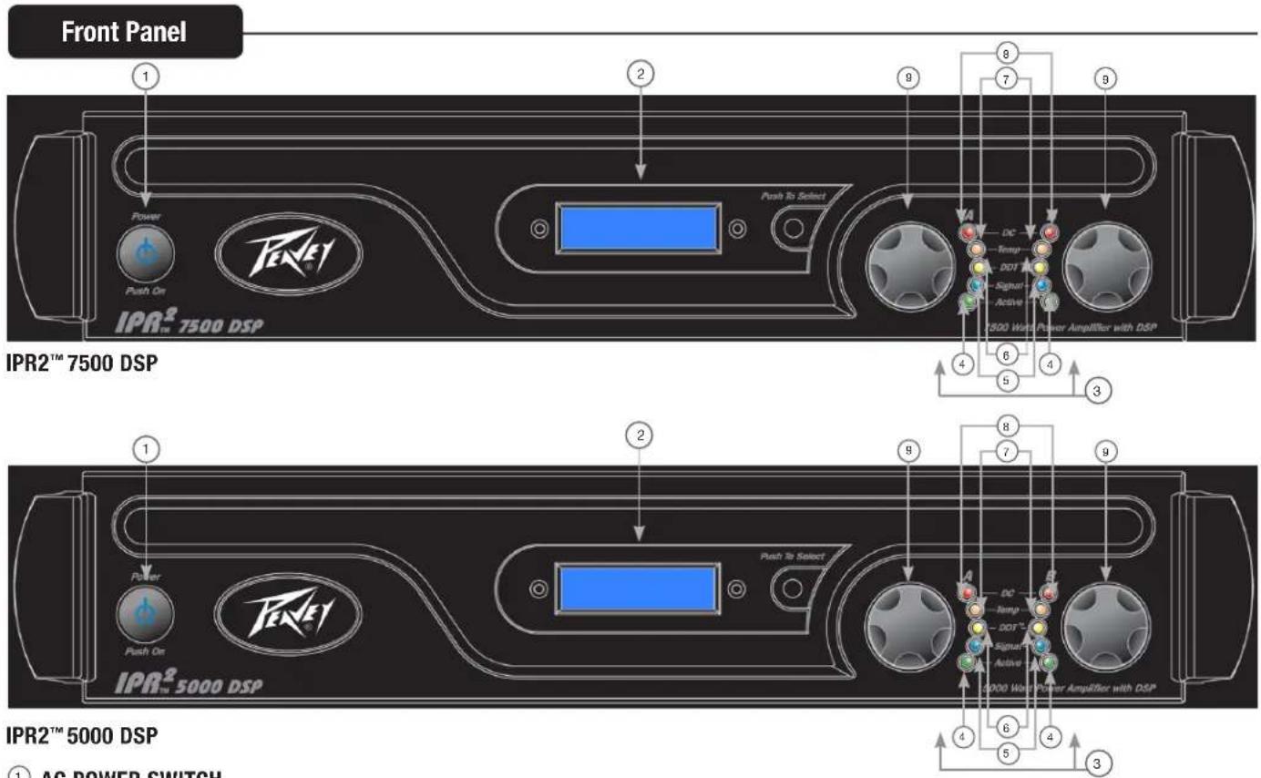
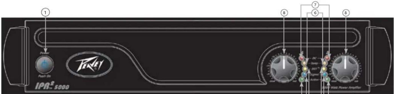
AC POWER SWITCH
This button triggers the relay that provides power to the amplifier. This unique power switch will glow blue dimly. When turned on, it illuminates brightly.
INDICATORS
The IPR2 ^™ amplifiers feature five front-panel LED indicators per channel: ACTIVE, SIGNAL, DDT ^™ , TEMP and DC. These LED indicators inform the user of each channel's operating status and warn of possible abnormal conditions.
ACTIVE LED
The Active LED indicates that its channel's output is closed and the channel is operational. It lights under normal operation and remains on, even when the channel is in DDT gain reduction. These protection features leave the output relay closed. If the Active LED goes off, there is no signal at the output connectors.
SIGNAL LED
This LED lights when its channel produces an output signal of about 4 volts RMS or more (0.1 volt or more at the input, with 0 dB attenuation and standard x40 voltage gain). This signal indicates whether a signal is reaching and being amplified by the amplifier.
DDT™ (DISTORTION DETECTION TECHNIQUE) LED
A channel's DDT™ LED will light at the onset of clipping. If the LEDs are flashing quickly and intermittently, the channel is just at the clip threshold. A steady, bright glow means the amp is clip limiting, or reducing gain to prevent severely clipped waveforms from reaching the loudspeakers. See the Distortion Detection Technique section for more information. During initial power-up the DDT LED will light to indicate that the gain reduction circuitry is activated. This prevents sudden signal bursts when the speaker relays are closed.
TEMP LED
In the unlikely event of an unstable thermal condition, amplifier protection will be activated and will shut down the offending channel. The Temp LED will remain illuminated until safe operating temperatures have returned.
DC LED
In the event of abnormal operating conditions, the IPR has built-in amplifier protection. Under conditions that would normally damage the power amplifier, the DC LED will illuminate and the amp will automatically attempt to restart to correct the condition. If the amplifier does not return to normal operating status, contact your local authorized service center.
INPuT ATTENUATORS
Whenever possible, set the attenuators fully clockwise to maintain optimum system headroom. The input attenuator controls, located at the front panel (one for channel A, one for channel B), adjust gain for their respective amplifier channels in all modes. See the specifications at the end of this manual for standard voltage gain and input sensitivity information.
Rear Panel
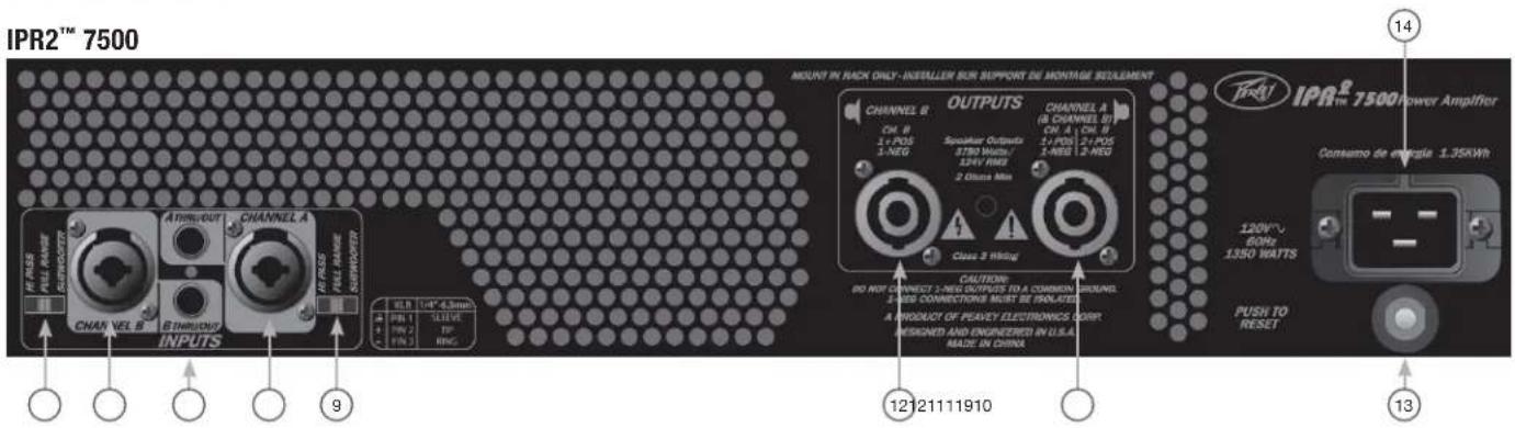
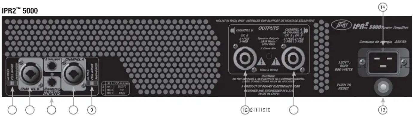
⑨ CHANNEL MODE SWITCH:
HIGH PASS
This position is used to activate the HIGH PASS filter for the corresponding channel. This filter will limit the frequencies sent to the associated amplifier channel to frequencies above 100 Hz. In situations where separate subwoofer cabinets are being used, this position would indicate connecting the mid-high frequency speaker cabinet to the channel associated with the HIGH PASS switch.
FuLL RANGE
As the name implies, the Full Range position on this switch allows all frequencies to pass to the amplifier. Normally used when connecting a full range speaker enclosure to the amplifier's output.
SuBWOOFER
This position is used to activate the LOW PASS filter for the corresponding channel. This filter will limit the frequencies sent to the associated amplifier channel to frequencies below 100 Hz. In situations where separate subwoofer cabinets are being used, this position would indicate connecting the subwoofer speaker cabinet to the channel associated with the Subwoofer switch.
THRU/OUT JACKS
This 1/4" jack supplies parallel output signals from the associated channel for patching to this amplifier and/or additional power amplifier inputs.
CONNECTING INPUTS
Input connections are made via the 3-pin XLR (pin 2+) or 6.3 mm plug combination connectors on the rear panel of the amplifier. The inputs are actively balanced.
CONNECTING OUTPUTS
All models have one combination 4 pole twist lock output connector per channel. Channel A output allows for CH A 1+ Pos / 1- Neg and channel B 2+ Pos / 2- Neg to use a single 4 conductor speaker cable.
Rear Panel

CIRCUIT BREAKER
In the unlikely event of operating conditions that may potentially damage the amplifier, the circuit breaker may trip. After inspecting the cables and connections, the amplifier can be reset. If the circuit breaker trips a second time, contact the local Peavey authorized service center.
AC POWER INLET:
This is the receptacle for an IEC line cord, which provides AC power to the unit. Connect the line cord to this connector to provide power to the unit. Damage to the equipment may result if improper line voltage is used. (See line voltage marking on unit). The 120VAC IPRZ ^™ 7500 gets a power cord retaining clamp.
Never break off the ground pin on any equipment. It is provided for your safety. If the outlet used does not have a ground pin, a suitable grounding adapter should be used and the third wire should be grounded properly. To prevent the risk of shock or fire hazard, always make sure that the amplifier and all associated equipment is properly grounded.
NOTE: FOR U.K. ONLY
As the colors of the wires in the mains lead of this apparatus may not correspond with the colored markings identifying the terminals in your plug, proceed as follows: (1) The wire which is colored green and yellow must be connected to the terminal which is marked by the letter E, or by the Earth symbol, or colored green or green and yellow. (2) The wire which is colored blue must be connected to the terminal which is marked with the letter N, or the color black. (3) The wire which is colored brown must be connected to the terminal which is marked with the letter L, or the color red.
ENGLISH
IPR2™ 5000/7500 DSP
Power Amplifier
As the name implies, the IPR2 ^™ 5000 and 7500 DSP all include advanced digital signal processing. The DSP was designed to be incredibly effective, yet extremely easy to use. Using unique and revolutionary advanced bass enhancement processes, the IPR2 DSP amplifiers dramatically improve the perceived level of bass in any system, using a fraction of the power that would be required with any other power amp.
Before you send signal through your amplifier, it is very important to ensure that the product has the proper AC line voltage supplied. You can find the proper voltage for your amp printed next to the IEC line (power) cord on the rear panel of the unit. Each product feature is numbered. Refer to the front panel diagram in this manual to locate the particular features next to its number.

Please read this guide carefully to ensure your personal safety as well as the safety of your amplifier.
IPR2™ 5000 / 7500 DSP FEATURES:
- DDT™ protection
• Revolutionary IPR class D topology - Combination XLR 1/4" inputs
• 4 pole twist lock output connector - Light weight
- Individual signal pass-thru 1/4" jacks on each channel
- LED illuminated
- DSP-based Loudspeaker Management System
• 120 ms of delay per channel - 4 bands of parametric equalization per channel
- Security lock
- Adjustable Crossover
- Adjustable fourth-order high-pass filter each channel
- MAXX Bass ^
- Horn EQ each channel
- Blue, backlit LCD screen

WARNING: PLEASE REVIEW YOUR DSP SETTINGS BEFORE SENDING SIGNAL TO THE AMPLIFIER. INCORRECT SETTINGS CAN POTENTIALLY DAMAGE SPEAKER ENCLOSURES.

VENTILATION: For proper ventilation, allow 12" clearance from nearest combustible surface. Make sure that vents are not blocked and air can flow freely through the unit.

WARNING: Changes or modifications to this unit not expressly approved by the party responsible for compliance could void the user's authority to operate the equipment.
NOTE: This equipment has been tested and found to comply with the limits for a Class A digital device, pursuant to Part 15 of the FCC Rules. These limits are designed to provide reasonable protection against harmful interference in a residential installation. This equipment generates, uses and can radiate radio frequency energy, and if not installed and used in accordance with the instructions, may cause harmful interference to radio communications.
However, there is no guarantee that interference will not occur in a particular installation. If this equipment does cause harmful interference to radio or television reception, which can be determined by turning the equipment off and on, the user is encouraged to try to correct the interference by one or more of the following measures:
- Reorient or relocate the receiving antenna.
- Increase the separation between the equipment and receiver.
- Connect the equipment into an outlet on a circuit different from that to which the receiver is connected.
- Consult the dealer or and experienced radio/TV technician for help.
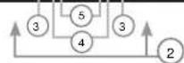
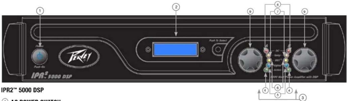
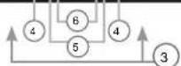
① AC POWER SWITCH
This button triggers the relay that provides power to the amplifier. This unique power switch will glow blue (along with the Peavey logo) in standby mode, indicating AC power has been connected to the amplifier but the amplifier has not yet been turned on.
② LCD SCREEN
Blue, backlit LCD screen.
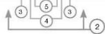
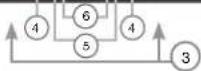
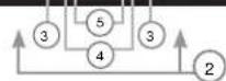
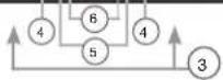
③ INDICATORS
The IPR2™ amplifiers feature five front-panel LED indicators per channel: ACTIVE, SIGNAL, DDT™, TEMP and DC. These LED indicators inform the user of each channel's operating status and warn of possible abnormal conditions.
④ ACTIVE LED
The Active LED indicates that its channel's output is closed and the channel is operational. It lights under normal operation and remains on, even when the channel is in DDT™ gain reduction. These protection features leave the output relay closed. If the Active LED goes off, there is no signal at the output connectors.
5 SIGNAL LED
This LED lights when its channel produces an output signal of about 4 volts RMS or more (0.1 volt or more at the input, with 0 dB attenuation and standard x40 voltage gain). This signal indicates whether a signal is reaching and being amplified by the amplifier.
6 DDT™ (DISTORTION DETECTION TECHNIQUE) LED
A channel's DDT LED will light at the onset of clipping. If the LEDs are flashing quickly and intermittently, the channel is just at the clip threshold. A steady, bright glow means the amp is clip limiting, or reducing gain to prevent severely clipped waveforms from reaching the loudspeakers. See the Distortion Detection Technique section for more information. During initial power-up the DDT LED will light to indicate that the gain reduction circuitry is activated. This prevents sudden signal bursts when the speaker relays are closed.
⑦ TEMP LED
In the unlikely event of an unstable thermal condition, amplifier protection will be activated and will shut down the offending channel. The Temp LED will remain illuminated until safe operating temperatures have returned.
⑧ DC LED
In the event of abnormal operating conditions, the IPR has built-in amplifier protection. Under conditions that would normally damage the power amplifier, the DC LED will illuminate and the amp will automatically attempt to restart to correct the condition. If the amplifier does not return to normal operating status, contact your local authorized service center.
9 INPuT ATTENuATORS
Whenever possible, set the attenuators fully clockwise to maintain optimum system headroom. The input attenuator controls, located at the front panel (one for channel A, one for channel B), adjust gain for their respective amplifier channels in all modes. See the specifications at the end of this manual for standard voltage gain and input sensitivity information.
Rear Panel
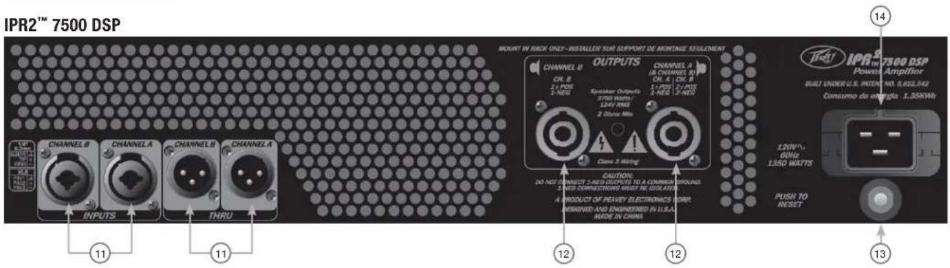
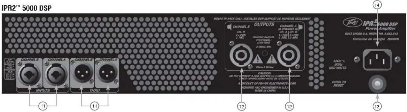
10 CONNECTING INPUTS
Input connections are made via the 3-pin XLR (pin 2+) or 6.3 mm plug combination connectors on the rear panel of the amplifier. The inputs are actively balanced. The input overload point is high enough to accept the maximum output level of virtually any signal source.
11 THRU/OUT JACKS
This XLR jack supplies output signals from the associated channel for patching to this amplifier and/or additional power amplifier inputs. The Thru/Out jack is affected by the position of the associated Channel Mode switch.
12 CONNECTING OUTPUTS
All models have one combination 4 pole twist lock output connector per channel. Channel A output allows for CH A 1+ Pos / 1-Neg and channel B 2+ Pos / 2-Neg to use a single 4 conductor speaker cable.
13 CIRCUIT BREAKER
In the unlikely event of operating conditions that may potentially damage the amplifier, the circuit breaker may trip. After inspecting the cables and connections, the amplifier can be reset. If the circuit breaker trips a second time, contact the local Peavey authorized service center.
14 AC POWER INLET:
This is the receptacle for an IEC line cord, which provides AC power to the unit. Connect the line cord to this connector to provide power to the unit. Damage to the equipment may result if improper line voltage is used. (See line voltage marking on unit).
Never break off the ground pin on any equipment. It is provided for your safety. If the outlet used does not have a ground pin, a suitable grounding adapter should be used and the third wire should be grounded properly. To prevent the risk of shock or fire hazard, always make sure that the amplifier and all associated equipment is properly grounded.
NOTE: FOR U.K. ONLY
As the colors of the wires in the mains lead of this apparatus may not correspond with the colored markings identifying the terminals in your plug, proceed as follows: (1) The wire which is colored green and yellow must be connected to the terminal which is marked by the letter E, or by the Earth symbol, or colored green or green and yellow. (2) The wire which is colored blue must be connected to the terminal which is marked with the letter N, or the color black. (3) The wire which is colored brown must be connected to the terminal which is marked with the letter L, or the color red.


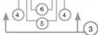
Navigation Overview
Once the IPR screen appears, you can start adjusting the DSP processor. Pressing the encoder will bring you to the main menu.
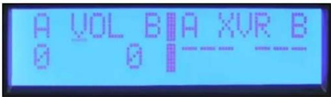
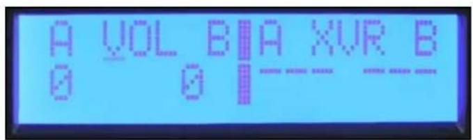
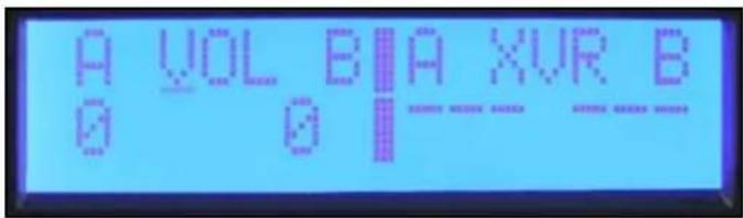
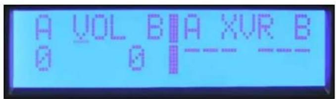
The encoder knob to the right of the display is used to navigate and control the DSP functions. The Channel A and B controls to the left of the display are also encoders but are dedicated to adjusting input gain for each channel. Turning the encoder knob to the right of the display will allow you to scroll through the Main Menu selections. The Main Menu not only allows you to select a process for editing, but also provides a quick view of which processes are activated.
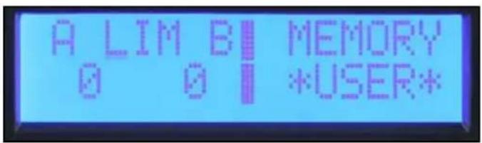
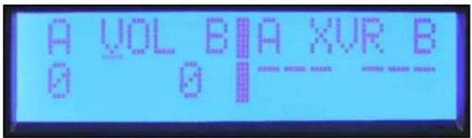
From left to right the menu selections are: Input Mode, Volume, Crossover/Band-Pass Filters, Equalization, Delay, Limiting, Memory and Lock.
Input Mode
Volume
Crossover / Band-Pass Filters
Equalization
Delay
Limiting
Memory Lock
To select an item from the Main Menu, rotate the encoder until the cursor marks the selection you want. Press the encoder to navigate to the Sub Menu adjustment screens for that processing function. When you enter a processing function Sub Menu, the cursor will appear in the upper left corner of the screen allowing you to scroll through Sub Menu screens. To edit a parameter, press the encoder to move the cursor to the desired parameter on the screen. Turning the encoder then adjusts that parameter. To scroll to another screen, press the encoder to return the cursor to the upper left corner of the screen. You can now scroll through Sub Menu screens.
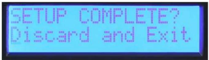
Discard and Exit
To reset the DSP and discard edits, select "Discard and Exit" from the Sub Menu to delete the edits made since entering the Sub Menu.
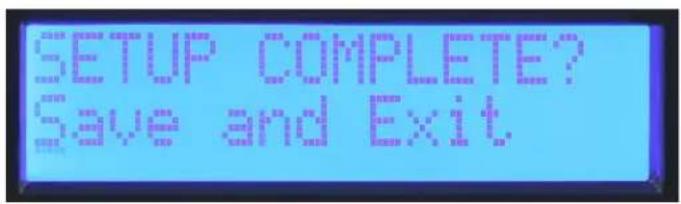
Save and Exit
The final screen in most process Sub Menus is "Save and Exit." Press the encoder in this screen to save the edits and return to the main menu.
Note: Adjustments made are not stored until Save and Exit is selected and you return to the main menu. Turning off the amplifier while editing in a Sub Menu gives the same result as "Discard and Exit."
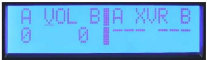
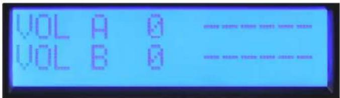
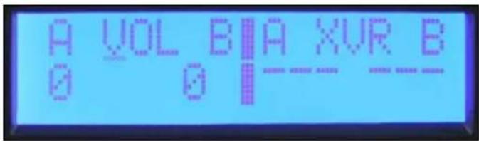
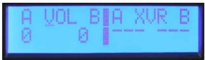
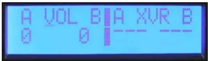
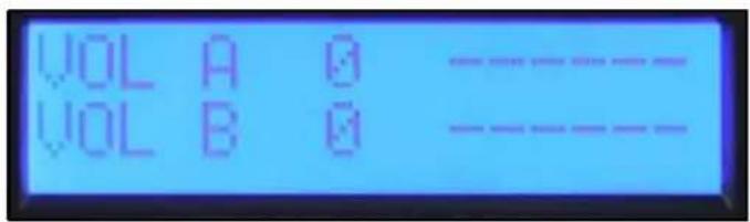
Volume
Volume
The current gain settings are always available in the main menu screen. The dedicated encoders on the front panel are used for adjustment of the A and B channels in stereo and mono modes. If the input mode is set to Bridge, the Channel B control is not active and the volume display shows "na."
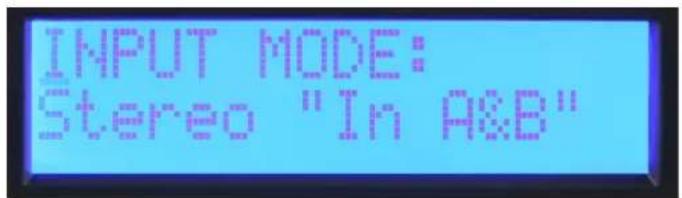
Mode
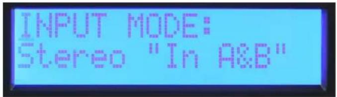
Stereo Input Mode
Stereo: Inputs A and B go to outputs A and B.

Mono Input Mode
Mono: Input A drives both outputs A and B.
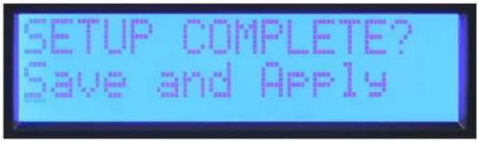
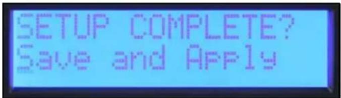
Unlike the other function Sub Menus, the input mode does not change until you select "Save and Apply" and return to the Main Menu.
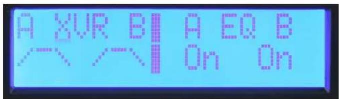
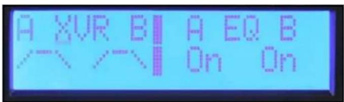
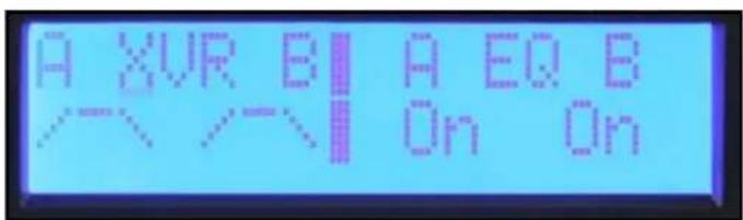
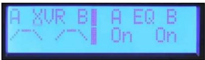
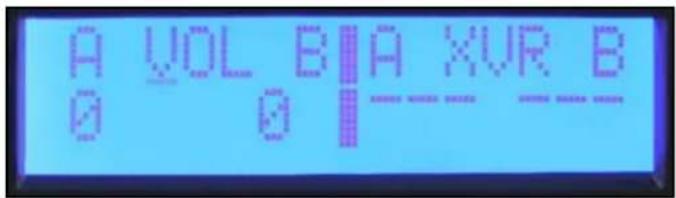
Crossover Filters, Band-Pass Filters and Polarity
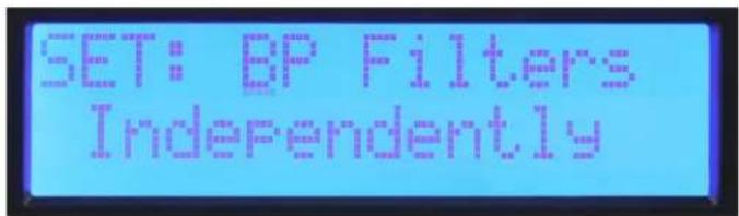
Set: BP Filters Independently
When you enter the "XOVER" Sub Menu, you are given three options for how the band-pass filters can be set. When Set "BP Filters Independently" is selected, the Channel A and B high-pass and low-pass filters are individually set.
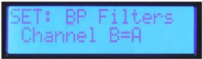
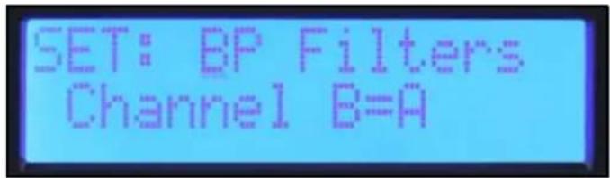
Set: BP Filters Channel B=A
If you are using the amplifier in a stereo system where both channels will be set the same, select "Channel B=A" and both channels will be set at once. Setting the filters for Channel A also sets Channel B.
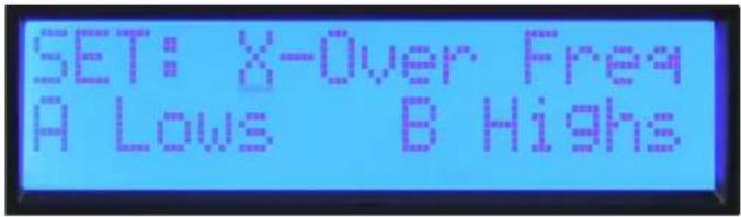
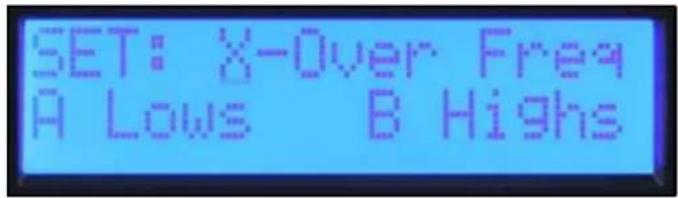
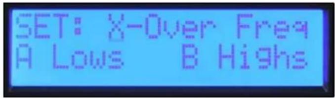
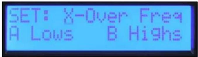
Set: X-Over Freq A Lows B Highs
If you create a crossover between channels of the amplifier, select "X-over Freq A Lows B Highs" and crossover frequency and filter type can be set with one set of controls. Set by crossover screen, High-pass and Low-pass screens.
The filter types available for the high-pass and low-pass filters are:
Off No filter
BW-12 dB Butterworth filter with 12 dB per octave slope. -3dB at corner frequency. Butterworth filters have a flat frequency response in the pass-band.
BW-18 dB Butterworth filter with 18 dB per octave slope. -3dB at corner frequency. Butterworth filters have a flat frequency response in the pass-band.
BW-24 dB Butterworth filter with 24 dB per octave slope. -3dB at corner frequency. Butterworth filters have a flat frequency response in the pass-band.
LR-24 dB Linkwitz-Riley Filter with 24 dB per octave slope. -6dB at corner frequency. LR filters combine for a flat response at the corner frequency.
It is generally a good idea to use a high-pass filter for all loudspeakers.
Output Polarity
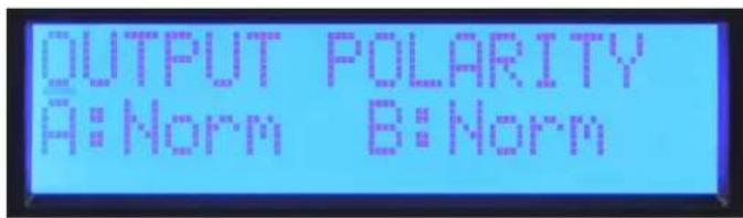
Output Polarity
The output polarity can be inverted on either channel. Select Normal or Invert in the polarity screen. If you create a crossover with 12dB per octave filters, the high frequency output would likely need to be inverted to maintain the proper phase relationship at the crossover frequency. Temporarily inverting the polarity of one channel of a multi-way system can also aid in the setting of the delay for driver alignment. You can adjust the delay for cancellation at the crossover frequency. Remember to switch the polarity back to Normal when complete.
To return to the Main Menu, select Discard and Exit or Save and Exit.
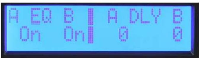
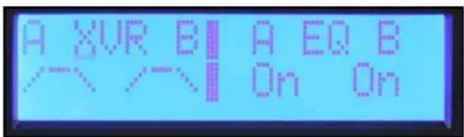
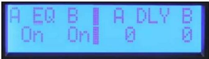
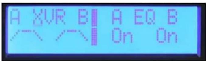
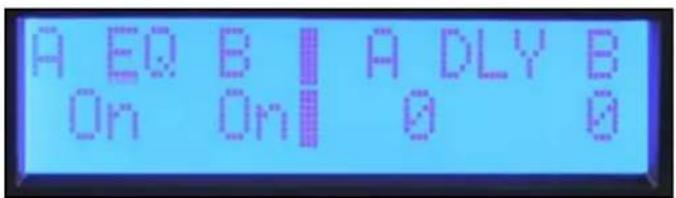
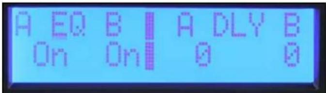
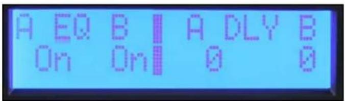
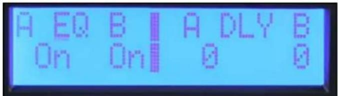
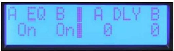
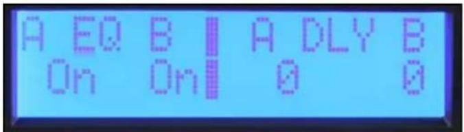
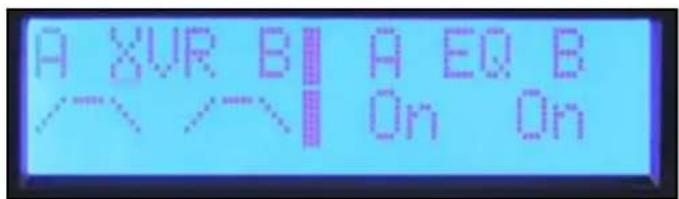
Equalization
The IPRZ™ DSP provides five bands of parametric EQ, Waves® Maxx Bass® enhancement and horn EQ on each channel.
Bypass
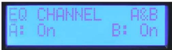
EQ Bypass
The first screen in the EQ Sub Menu is the bypass screen. The channels can be bypassed independently or both A&B can be bypassed together. Press the encoder until the cursor is under the desired parameter to change and rotate the encoder to change the bypass mode. Press the cursor to return it to the upper left corner when done so you can scroll to other screens.
Set Channel EQ
The first screen in the EQ Sub Menu is the bypass screen. The channels can be bypassed independently or both A&B can be bypassed together. Press the encoder until the cursor is under the desired parameter to change and rotate the encoder to change the bypass mode. Press the cursor to return it to the upper left corner when done so you can scroll to other screens.
MaxxBass®
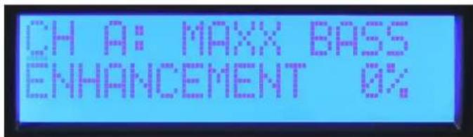
The MaxxBass ^® enhancement system interacts with the high-pass filter for each channel to produce bass energy in a frequency range the loudspeaker can handle. The higher the MaxxBass ^® number, the more the bass is enhanced.
Parametric EQ
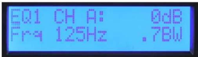
There are five bands of parametric EQ for each channel. The frequency can be set in 1/12 octave frequency steps. The filter bandwidth is set and displayed in octaves. The level can be adjusted over a +/- 15 dB range. Press the encoder to select the desired parameter to adjust. Return the cursor to the upper left corner when done to scroll to other screens.
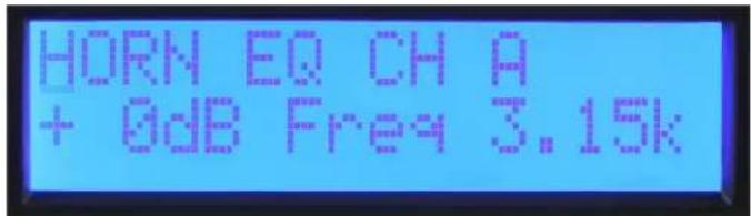
Horn EQ
The Horn EQ provides a 6dB per octave high frequency boost that is sometimes required for high frequency horns. The frequency control sets the low frequency corner of the filter.
To return to the Main Menu, select Discard and Exit or Save and Exit.
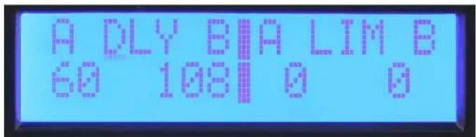
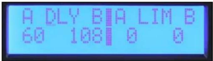
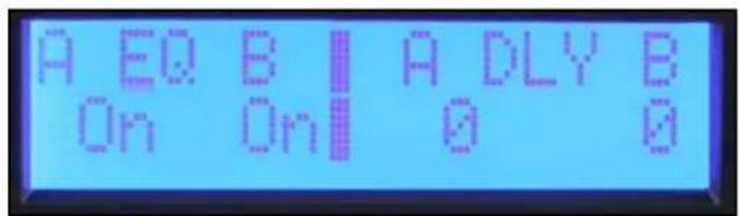
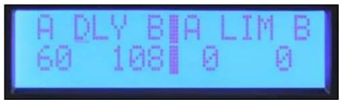
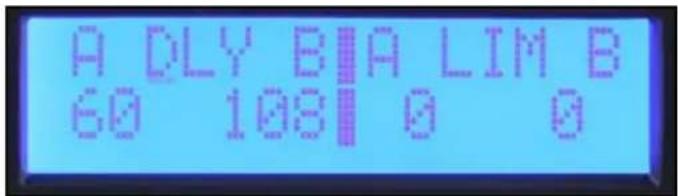
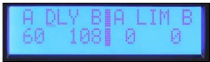
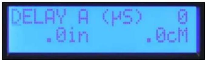
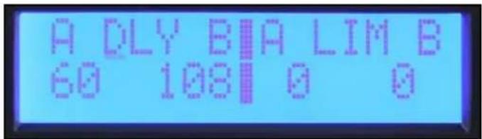
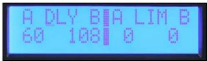
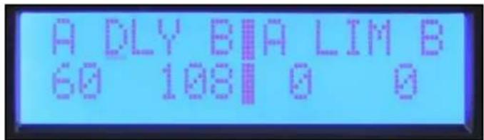
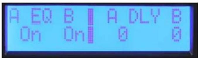
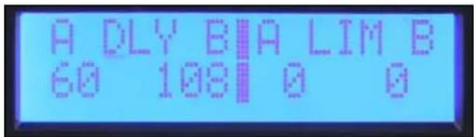
Delay
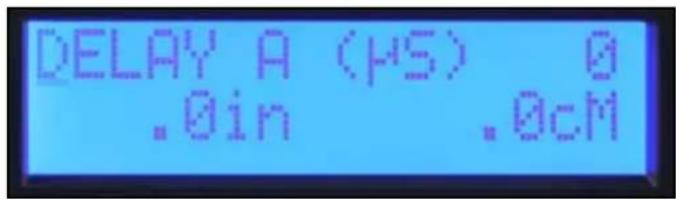
Delay can be used to align drivers within a loudspeaker or to delay auxiliary speakers like those installed under a balcony. A short delay can also be used to delay the main speakers to align them with the drums or bass guitar. A total of 125 mS of delay is available on each channel. 5 mS of delay is available in 41.67 uS steps for driver alignment. 120 mS is available in 1 mS steps for system alignment. These delays can be set independently so that the driver alignment offset can be maintained when the system alignment delay is adjusted.
The first screen in the delay Sub Menu allows the user to decide whether the delays will be set independently or B=A. This selection only applies to the 1 mS step system delay, leaving the driver alignment delays to be set independently. The IPR2 ^™ amplifiers display the equivalent delay distance in meters and feet in the system delay and centimeters or inches in the driver delay.
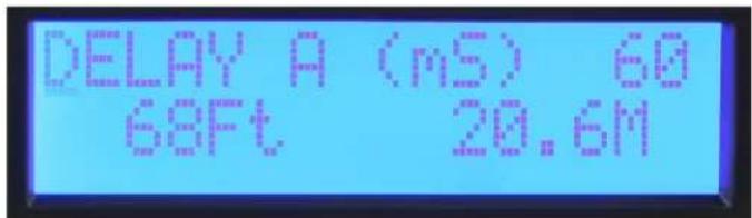
System (mS) Delay screen
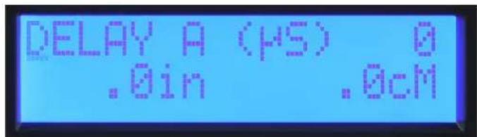
Driver alignment (uS) screen
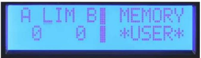
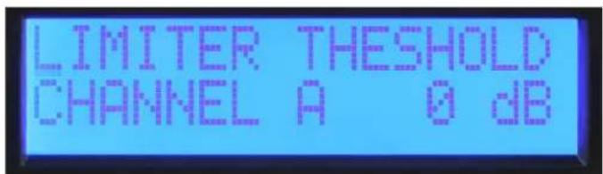
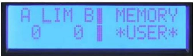
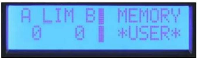
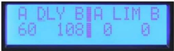
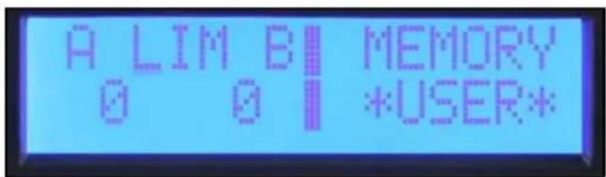
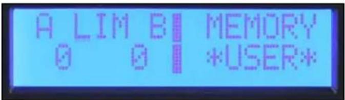
Limiter
The IPR2 DSP has limiters available on each channel. These limit the signal level to the input of the power amplifier stage. The limit threshold starts at zero and is adjusted in -1 dB steps, reducing the maximum output. You must be aware that the IPR2 DSP works the same as most other amplifiers in that their maximum output depends on the line voltage and load impedance. Depending on load, you may need to reduce the limiter up to 3 dB before the output is reduced.
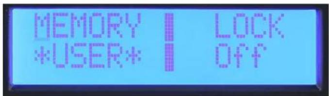
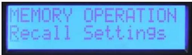
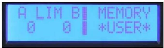
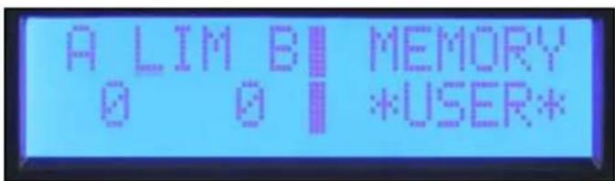
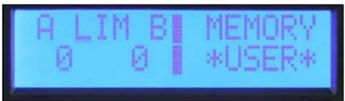
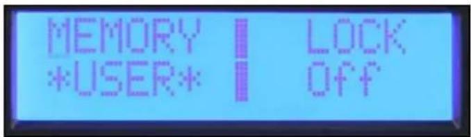
Memory
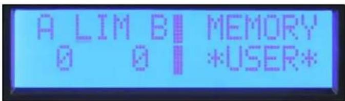
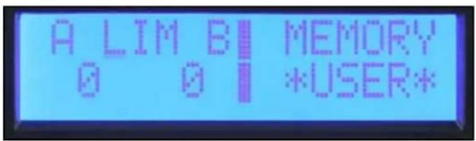
The IPR2 has four memory locations where its settings can be stored and then recalled. Each location has a six-character name to identify the file. The name of the active preset is also displayed in the Main Menu "Memory" screen.
Saving Settings
In the Memory Operation Sub Menu, select "Save Settings."
Select one of the four preset locations.
Edit the name by rotating the cursor to select the character and pressing the encoder to step to the next position. Continue until complete. To keep the same name, press the encoder six times to step through the name edit screen.
Once the save location has been selected and you have named the preset, you will be given a yes/no option to complete the save.

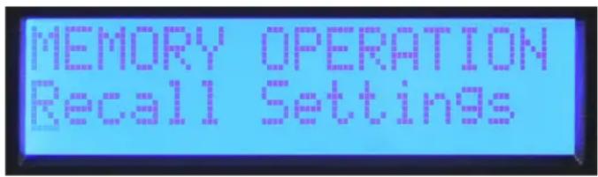
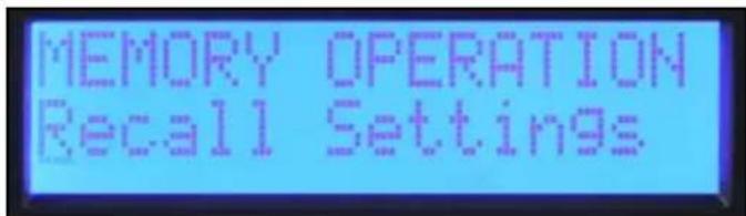
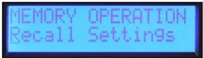
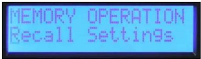
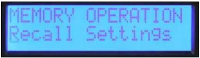
Recalling a Preset
In the Memory Operation Sub Menu, select "Recall Settings."
Select the Preset number to recall or select recall factory settings to recall a neutral state. Just like the save function, the option is given to exit without completing the recall option.
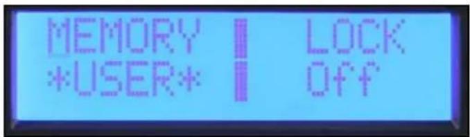
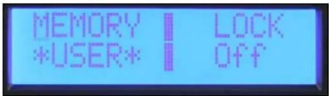
Lock
The security lock feature of the IPR2 ^™ DSP allows selected controls to be locked to prevent unauthorized adjustment. A four-digit password must be set when the lock is engaged. This password must be entered whenever a Sub Menu is entered to allow temporary access to the edit functions. The lock is re-engaged whenever you return the Main Menu or turn the unit off. All editing is locked when the power is off.
Note: Be sure to make note of the password. Contact customer service if the password is lost or misplaced.
The IPR2 amplifiers have three different lock modes:
Off All settings can be adjusted without entering a password.
All Except Volume A password must be entered for all edit Sub Menus except volume.
All with Volume A password must be entered for all edit Sub Menus including volume.
IPR2™ 7500 Specification Sheet
| Rated Watts 2ch x 2 ohms | 4750 watts 20ms repetitive burst / 3750 watts 1% THD both channels driven @ 1kHz. |
| Rated Watts 2ch x 4 ohms | 2800 watts 20ms repetitive burst / 2450 watts 1% THD / 2020 watts 0.15% THD, both channels driven @ 1kHz. |
| Rated Watts 2ch x 8 ohms | 1550 watts 20ms repetitive burst / 1425 watts 1% THD / 1200 watts 0.15% THD, both channels driven @ 1kHz. |
Minimum Impedance 2 ohms
Maximum RMS Voltage Swing 124 volts
Frequency Response 20Hz - 25kHz; +0dB, -3dB
20Hz - 20kHz 2ch x 2 ohms <0.5% @ 3280 watts 20Hz to 4kHz, decreasing to 3000 watts @ 20kHz, both channels driven.
20Hz - 20kHz 2ch x 4 ohms <0.15% @ 2000 watts 20Hz to 20kHz, both channels driven.
20Hz - 20kHz 2ch x 8 ohms <0.15% @ 1200 watts 20Hz to 20kHz, both channels driven.
Input CMRR > - 75dB @ 1 kHz.
Voltage Gain x 40 (+32dB)
Crossover 100Hz switchable 2nd order high pass and 3rd low pass per channel.
Crosstalk > -85dB @ 1kHz @ 1000 watts power @ 8 ohms.
Hum and Noise > -106dB, "A" weighted referenced to rated power @ 4 ohms.
Slew Rate > 12V/μs
Damping Factor (8 ohms) > 200:1 @ 20Hz - 1kHz @ 8 ohms
Input Sensitivity 2.25 volts +/- 3% for 1kHz 4 ohm rated power, 2.195 volts +/- 3% for 1kHz 2 ohm rated power
Input Impedance 20 kilohms, balanced and 10 kilohms unbalanced.
Current Draw @ 1/8 in VA (watts) 2210 (1440) @ 2 ohms, 1550 (950) @ 4 ohms, 982 (560) @ 8 ohms
Current Draw @ 1/3 in VA (watts) 4260 (3150) @ 2 ohm, 3120 (2160) @ 4 ohms, 1890 (1200) @ 8 ohms
Idle Consumption 250VA, 120 watts.
Cooling 3 temperature dependent variable speed fans.
Controls 2 front panel attenuators, crossover select switch for HPF, Normal and LPF
Indicator LEDs Five LED indicators per channel: Active, Signal, DDT, Temperature and DC
Protection Thermal, DC, subsonic, incorrect loads, under and over voltage
Connectors Inputs: Dual combination 1/4" XLR, Outputs: Dual 1/4" thru, one 2-pin & one 4 pin twist-lock connector
Construction 0.062" thick aluminum
Dimensions 3.5"x19"x17" behind front panel + 0.6" for handle
Net Weight 6.61kg (14.6lbs.*)
Gross Weight 8.34kg (18.4lbs.)
Rated power readings made with BW: 20 Hz to 22 kHz. All power measurements made @ 120 VAC or 240VAC.
2 ohm steady state sine wave power is time limited by circuit breaker.
Bridge operation is not possible.
*Net Weight does not include power cord.
IPR2™ 5000 Specification Sheet
| Rated Watts 2ch x 2 ohms | 3230 watts 20ms repetitive burst / 2530 watts 1% THD both channels driven @ 1kHz. |
| Rated Watts 2ch x 4 ohms | 1985 watts 20ms repetitive burst / 1700 watts 1% THD / 1470 watts 0.15% THD, both channels driven @ 1kHz. |
| Rated Watts 2ch x 8 ohms | 1175 watts 20ms repetitive burst / 1025 watts 1% THD / 880 watts 0.15% THD, both channels driven @ 1kHz. |
Minimum Load Impedance 2 ohms
Maximum RMS Voltage Swing 105 volts
Frequency Response 20Hz - 22kHz; +/- 0.5dB at 1 watt.
| 20Hz - 20kHz 2ch x 2 ohms | <0.5% @ 2250 watts 20Hz to 4kHz, decreasing to 1640 watts @ 20kHz, both channels driven. |
| 20Hz - 20kHz 2ch x 4 ohms | <0.15% @ 1400 watts 20Hz to 10kHz, decreasing to 1350 watts @ 20kHz, both channels driven. |
| 20Hz - 20kHz 2ch x 8 ohms | <0.15% @ 860 watts 20Hz to 4kHz, increasing to 1000 watts @ 20kHz, both channels driven. |
Input CMRR > - 75dB @ 1 kHz.
Voltage Gain x 40 (+32dB)
Crossover 100Hz switchable 2nd order high pass and 3rd low pass per channel.
Crosstalk > -60dB @ 1kHz @ 700 watts power @ 8 ohms.
Hum and Noise > -105dB, "A" weighted referenced to rated power @ 4 ohms.
Slew Rate > 12V/μs
Damping Factor (8 ohms) >210:1 @ 20Hz - 1kHz @ 8 ohms
Input Sensitivity 1.95 volts +/- 3% for 1kHz 4 ohm rated power, 1.83 volts +/- 3% for 1kHz 2 ohm rated power
Input Impedance 20 kilohms, balanced and 10 kilohms unbalanced.
Current Draw @ 1/8 in VA (watts) 1435 (890) @ 2 ohms, 920 (525) @ 4 ohms, 625 (335) @ 8 ohms
Current Draw @ 1/3 in VA (watts) 3050 (2155) @ 2 ohms, 1880 (1200) @ 4 ohms, 1200 (715) @ 8 ohms
Idle Consumption 195VA, 90 watts.
Cooling 3 temperature dependent variable speed fans.
Controls 2 front panel attenuators, crossover select switch for HPF, Normal and LPF
Indicator LEDs Five LED indicators per channel: Active, Signal, DDT, Temperature and DC
Protection Thermal, DC, subsonic, incorrect loads, under and over voltage
Connectors Inputs: Dual combination 1/4" XLR, Outputs: Dual 1/4" thru, one 2-pin & one 4 pin twist-lock connector
Construction 0.062" thick aluminum
Dimensions 3.5"x19"x17" behind front panel + 0.6" for handle
Net Weight 6.2 kg (13.6 lbs.*)
Gross Weight 7.9 kg (17.4 lbs.)
Rated power readings made with BW: 20 Hz to 22 kHz. All power measurements made @ 120 VAC or 240VAC.
2 ohm steady state sine wave power is time limited by circuit breaker.
Bridge operation is not possible.
*Net Weight does not include power cord.
IPR2 7500 DSP Specification Sheet
| Rated Watts 2ch x 2 ohms | 4750 watts 20ms repetitive burst / 3750 watts 1% THD both channels driven @ 1kHz. |
| Rated Watts 2ch x 4 ohms | 2800 watts 20ms repetitive burst / 2450 watts 1% THD / 2020 watts 0.15% THD, both channels driven @ 1kHz. |
| Rated Watts 2ch x 8 ohms | 1550 watts 20ms repetitive burst / 1425 watts 1% THD / 1200 watts 0.15% THD, both channels driven @ 1kHz. |
Minimum Impedance 2 ohms
Maximum RMS Voltage Swing 124 volts
Frequency Response 20Hz - 25kHz; +0dB, -3dB
20Hz - 20kHz 2ch x 2 ohms <0.5% @ 3280 watts 20Hz to 4kHz, decreasing to 3000 watts @ 20kHz, both channels driven.
20Hz - 20kHz 2ch x 4 ohms <0.15% @ 2000 watts 20Hz to 20kHz, both channels driven.
20Hz - 20kHz 2ch x 8 ohms <0.15% @ 1200 watts 20Hz to 20kHz, both channels driven.
Input CMRR > - 75dB @ 1 kHz.
Voltage Gain x 70 (+37 dB)
Crossover Adjustable High Pass and Low Pass filter per channel. Filter Types: 12dB/oct 2nd order, 18dB/oct 3rd order, 24dB/oct 4th order Butterworth and 24dB/oct 4th order Linkwitz –Riley
Crosstalk > -60dB @ 1kHz @ 1000 watts power @ 8 ohms.
Hum and Noise > -95dB, "A" weighted referenced to rated power @ 4 ohms.
Slew Rate > 12V/μs
Damping Factor (8 ohms) > 200:1 @ 20Hz - 1kHz @ 8 ohms
Input Sensitivity 1.290 volts +/- 3% for 1 kHz 4 ohm rated power, 1.240 volts +/- 3% for 1 kHz 2 ohm rated power
Input Impedance 12 kilohms, balanced and 10 kilohms unbalanced.
Current Draw @ 1/8 in VA (watts) 2210 (1440) @ 2 ohms, 1550 (950) @ 4 ohms, 982 (560) @ 8 ohms
Current Draw @ 1/3 in VA (watts) 4260 (3150) @ 2 ohms, 3120 (2160) @ 4 ohms, 1890 (1200) @ 8 ohms
Idle Consumption 250VA, 120 watts.
Cooling 3 temperature dependent variable speed fans.
Controls 2 front panel detented attenuators, push-button navigation encoder to navigate through the menus on the LCD screen for input mode, parametric EQ, crossover H.P.F, Normal, L.P.F. and more.
Indicator LEDs Five LED indicators per channel: Active, Signal, DDT, Temperature and DC
Protection Thermal, DC, subsonic, incorrect loads, under and over voltage
Connectors Inputs: Dual combination 1/4" XLR, Outputs: Dual male XLR input thru, one 2-pin & one 4 pin twist-lock connectors
Construction 0.062" thick aluminum
Dimensions 3.5"x19"x17" behind front panel + 0.6" for handle
Net Weight 6.61kg (14.6lbs.*)
Gross Weight 8.34kg (18.4lbs.)
Rated power readings made with BW: 20 Hz to 22 kHz. All power measurements made @ 120 VAC or 240VAC.
2 ohm steady state sine wave power is time limited by circuit breaker.
Bridge operation is not possible.
*Net Weight does not include power cord.
IPR2™ 5000 DSP Specification Sheet
| Rated Watts 2ch x 2 ohms | 3230 watts 20ms repetitive burst / 2530 watts 1% THD both channels driven @ 1kHz. |
| Rated Watts 2ch x 4 ohms | 1985 watts 20ms repetitive burst / 1700 watts 1% THD / 1470 watts 0.15% THD, both channels driven @ 1kHz. |
| Rated Watts 2ch x 8 ohms | 1175 watts 20ms repetitive burst / 1025 watts 1% THD / 880 watts 0.15% THD, both channels driven @ 1kHz. |
Minimum Load Impedance 2 ohms
Maximum RMS Voltage Swing 105 volts
Frequency Response 20Hz - 22kHz; +/- 0.5dB at 1 watt.
20Hz - 20kHz 2ch x 2 ohms <0.5% @ 2250 watts 20Hz to 4kHz, decreasing to 1640 watts @ 20kHz, both channels driven.
20Hz - 20kHz 2ch x 4 ohms <0.15% @ 1400 watts 20Hz to 10kHz, decreasing to 1350 watts @ 20kHz, both channels driven.
20Hz - 20kHz 2ch x 8 ohms <0.15% @ 860 watts 20Hz to 4kHz, increasing to 1000 watts @ 20kHz, both channels driven.
Input CMRR > - 75dB @ 1 kHz.
Voltage Gain x 70 (+37dB)
Crossover Adjustable High Pass and Low Pass filter per channel. Filter Types: 12dB/oct 2nd order, 18dB/oct 3rd order, 24dB/oct 4th order Butterworth and 24dB/oct 4th order Linkwitz –Riley.
Crosstalk -60dB @ 1kHz @ 700 watts power @ 8 ohms.
Hum and Noise > -96dB, "A" weighted referenced to rated power @ 4 ohms.
Slew Rate > 12V/μs
Damping Factor (8 ohms) > 210:1 @ 20Hz - 1kHz @ 8 ohms
Input Sensitivity 1.094 volts +/- 3% for 1 kHz 4 ohm rated power, 1.025 volts +/- 3% for 1 kHz 2 ohm rated power.
Input Impedance 12 kilohms, balanced and 6 kilohms unbalanced.
Current Draw @ 1/8 in VA (watts) 1435 (890) @ 2 ohms, 920 (525) @ 4 ohms, 625 (335) @ 8 ohms
Current Draw @ 1/3 in VA (watts) 3050 (2155) @ 2 ohms, 1880 (1200) @ 4 ohms, 1200 (715) @ 8 ohms
Idle Consumption 195VA, 90 watts.
Cooling 3 temperature dependent variable speed fans.
Controls 2 front panel attenuators, crossover select switch for HPF, Normal and LPF
Indicator LEDs Five LED indicators per channel: Active, Signal, DDT, Temperature and DC
Protection Thermal, DC, subsonic, incorrect loads, under and over voltage
Connectors Inputs: Dual combination 1/4" XLR, Outputs: Dual male XLR input thru, one 2-pin & one 4 pin twist-lock connector
Construction 0.062" thick aluminum
Dimensions 3.5"x19"x17" behind front panel + 0.6" for handle
Net Weight 6.2 kg (13.6 lbs.*)
Gross Weight 7.9 kg (17.4 lbs.)
Rated power readings made with BW: 20 Hz to 22 kHz. All power measurements made @ 120 VAC or 240VAC.
2 ohm steady state sine wave power is time limited by circuit breaker.
Bridge operation is not possible.
*Net Weight does not include power cord.
ESPAÑOL
IPR2™ 5000 / 7500
INTERRUPTOR POWER
CIRCUIT BREAKER
As the colors of the wires in the mains lead of this apparatus may not correspond with the colored markings identifying the terminals in your plug, proceed as follows: (1) The wire which is colored green and yellow must be connected to the terminal which is marked by the letter E, or by the Earth symbol, or colored green or green and yellow. (2) The wire which is colored blue must be connected to the terminal which is marked with the letter N, or the color black. (3) The wire which is colored brown must be connected to the terminal which is marked with the letter L, or the color red.
ESPAÑOL
IPR2™ 5000/7500 DSP
As the colors of the wires in the mains lead of this apparatus may not correspond with the colored markings identifying the terminals in your plug, proceed as follows: (1) The wire which is colored green and yellow must be connected to the terminal which is marked by the letter E, or by the Earth symbol, or colored green or green and yellow. (2) The wire which is colored blue must be connected to the terminal which is marked with the letter N, or the color black. (3) The wire which is colored brown must be connected to the terminal which is marked with the letter L, or the color red.
Modo de entrada

Volumen
Limitador
Bloqueo de memoria
Discard and Exit
Save and Exit
Stereo Input Mode
Mono Input Mode
Set: BP Filters Independently
Set: BP Filters Channel B=A

Output Polarity
EQ Bypass
Guardar ajustes

Bloqueo
CIRCUIT BREAKER
As the colors of the wires in the mains lead of this apparatus may not correspond with the colored markings identifying the terminals in your plug, proceed as follows: (1) The wire which is colored green and yellow must be connected to the terminal which is marked by the letter E, or by the Earth symbol, or colored green or green and yellow. (2) The wire which is colored blue must be connected to the terminal which is marked with the letter N, or the color black. (3) The wire which is colored brown must be connected to the terminal which is marked with the letter L, or the color red.
FRANÇAIS
IPR2™ 5000/7500 DSP
As the colors of the wires in the mains lead of this apparatus may not correspond with the colored markings identifying the terminals in your plug, proceed as follows: (1) The wire which is colored green and yellow must be connected to the terminal which is marked by the letter E, or by the Earth symbol, or colored green or green and yellow. (2) The wire which is colored blue must be connected to the terminal which is marked with the letter N, or the color black. (3) The wire which is colored brown must be connected to the terminal which is marked with the letter L, or the color red.
Input Mode
Volume

Crossover / Band-Pass Filters
Equalization
Delay
Limiting

Memory Lock
Discard and Exit
Save and Exit
Stereo Input Mode
Mono Input Mode
Set: BP Filters Independently
Set: BP Filters Channel B=A


Output Polarity
EQ Bypass
Saving Settings
Lock
CIRCUIT BREAKER
As the colors of the wires in the mains lead of this apparatus may not correspond with the colored markings identifying the terminals in your plug, proceed as follows: (1) The wire which is colored green and yellow must be connected to the terminal which is marked by the letter E, or by the Earth symbol, or colored green or green and yellow. (2) The wire which is colored blue must be connected to the terminal which is marked with the letter N, or the color black. (3) The wire which is colored brown must be connected to the terminal which is marked with the letter L, or the color red.
NEDERLANDS
IPR2™ 5000/7500 DSP
Eindversterker
As the colors of the wires in the mains lead of this apparatus may not correspond with the colored markings identifying the terminals in your plug, proceed as follows: (1) The wire which is colored green and yellow must be connected to the terminal which is marked by the letter E, or by the Earth symbol, or colored green or green and yellow. (2) The wire which is colored blue must be connected to the terminal which is marked with the letter N, or the color black. (3) The wire which is colored brown must be connected to the terminal which is marked with the letter L, or the color red.


Navigatie-overzicht
Input Mode

Volume
Crossover / Band-Pass Filters
Equalization
Delay
Limiting

Memory Lock
Discard and Exit
Save and Exit
Stereo Input Mode
Mono Input Mode
Set: BP Filters Independently
Set: BP Filters Channel B=A


Output Polarity
EQ Bypass
Memory
Lock
CIRCUIT BREAKER
As the colors of the wires in the mains lead of this apparatus may not correspond with the colored markings identifying the terminals in your plug, proceed as follows: (1) The wire which is colored green and yellow must be connected to the terminal which is marked by the letter E, or by the Earth symbol, or colored green or green and yellow. (2) The wire which is colored blue must be connected to the terminal which is marked with the letter N, or the color black. (3) The wire which is colored brown must be connected to the terminal which is marked with the letter L, or the color red.
SUOMI
IPR2™ 5000/7500 DSP
Päätevahvistin
As the colors of the wires in the mains lead of this apparatus may not correspond with the colored markings identifying the terminals in your plug, proceed as follows: (1) The wire which is colored green and yellow must be connected to the terminal which is marked by the letter E, or by the Earth symbol, or colored green or green and yellow. (2) The wire which is colored blue must be connected to the terminal which is marked with the letter N, or the color black. (3) The wire which is colored brown must be connected to the terminal which is marked with the letter L, or the color red.


Input Mode
Volume
Crossover / Band-Pass Filters

Equalization
Delay
Limiting

Memory Lock
Discard and Exit
Save and Exit
Stereo Input Mode
Mono Input Mode
Set: BP Filters Independently
Set: BP Filters Channel B=A

Output Polarity
EQ Bypass
Memory
Lock
① STRÖMBRYTARE
CIRCUIT BREAKER
As the colors of the wires in the mains lead of this apparatus may not correspond with the colored markings identifying the terminals in your plug, proceed as follows: (1) The wire which is colored green and yellow must be connected to the terminal which is marked by the letter E, or by the Earth symbol, or colored green or green and yellow. (2) The wire which is colored blue must be connected to the terminal which is marked with the letter N, or the color black. (3) The wire which is colored brown must be connected to the terminal which is marked with the letter L, or the color red.
SVENSKA
IPR2™ 5000/7500 DSP
Effektförstärkare
① AC POWER SWITCH
As the colors of the wires in the mains lead of this apparatus may not correspond with the colored markings identifying the terminals in your plug, proceed as follows: (1) The wire which is colored green and yellow must be connected to the terminal which is marked by the letter E, or by the Earth symbol, or colored green or green and yellow. (2) The wire which is colored blue must be connected to the terminal which is marked with the letter N, or the color black. (3) The wire which is colored brown must be connected to the terminal which is marked with the letter L, or the color red.


Input Mode
Volume

Crossover / Band-Pass Filters
Equalization
Delay
Limiting

Memory Lock
Discard and Exit
Save and Exit
Stereo Input Mode
Mono Input Mode
Set: BP Filters Independently
Set: BP Filters Channel B=A


Output Polarity
EQ Bypass
Saving Settings
I undermenyn för minnesoperation, välj "Save Settings."
Lock
Ingång CMRR > - 75dB @ 1 kHz.
Ingång CMRR > - 75dB @ 1 kHz.
Ingång CMRR > - 75dB @ 1 kHz.
Ingång CMRR > - 75dB @ 1 kHz.
CIRCUIT BREAKER
As the colors of the wires in the mains lead of this apparatus may not correspond with the colored markings identifying the terminals in your plug, proceed as follows: (1) The wire which is colored green and yellow must be connected to the terminal which is marked by the letter E, or by the Earth symbol, or colored green or green and yellow. (2) The wire which is colored blue must be connected to the terminal which is marked with the letter N, or the color black. (3) The wire which is colored brown must be connected to the terminal which is marked with the letter L, or the color red.
NORSK
IPR2™ 5000/7500 DSP
Effektforsterker
As the colors of the wires in the mains lead of this apparatus may not correspond with the colored markings identifying the terminals in your plug, proceed as follows: (1) The wire which is colored green and yellow must be connected to the terminal which is marked by the letter E, or by the Earth symbol, or colored green or green and yellow. (2) The wire which is colored blue must be connected to the terminal which is marked with the letter N, or the color black. (3) The wire which is colored brown must be connected to the terminal which is marked with the letter L, or the color red.


Navigeringsoversikt
Input Mode

Volume

Crossover / Band-Pass Filters

Equalization
Delay
Limiting

Memory Lock
Discard and Exit
Save and Exit
Stereo Input Mode
Mono Input Mode
Set: BP Filters Independently
Set: BP Filters Channel B=A


Tilgjengelige filtertyper for high-pass-/low-pass-filtre:
Off Ingen filter
Output Polarity
EQ Bypass
System (mS) Delay screen
Driver alignment (uS) screen
Limiter
Memory
Hent forhåndsinnstilt
I undermenyen "Memory Operation", velg "Recall Settings."
CIRCUIT BREAKER
As the colors of the wires in the mains lead of this apparatus may not correspond with the colored markings identifying the terminals in your plug, proceed as follows: (1) The wire which is colored green and yellow must be connected to the terminal which is marked by the letter E, or by the Earth symbol, or colored green or green and yellow. (2) The wire which is colored blue must be connected to the terminal which is marked with the letter N, or the color black. (3) The wire which is colored brown must be connected to the terminal which is marked with the letter L, or the color red.
ITALIANO
IPR2™ 5000/7500 DSP
As the colors of the wires in the mains lead of this apparatus may not correspond with the colored markings identifying the terminals in your plug, proceed as follows: (1) The wire which is colored green and yellow must be connected to the terminal which is marked by the letter E, or by the Earth symbol, or colored green or green and yellow. (2) The wire which is colored blue must be connected to the terminal which is marked with the letter N, or the color black. (3) The wire which is colored brown must be connected to the terminal which is marked with the letter L, or the color red.


Input Mode
Volume
Crossover / Band-Pass Filters
Equalization
Delay
Limiting
Memory Lock
Discard and Exit
Save and Exit
Stereo Input Mode
Mono Input Mode
Set: BP Filters Independently
Set: BP Filters Channel B=A

Output Polarity
EQ Bypass
System (mS) Delay screen
Driver alignment (uS) screen
Limiter
Memory

Lock
Ingresso CMRR > - 75dB @ 1 kHz.
Voltage Gain x 40 (+32dB)
Crosstalk > -85dB @ 1kHz @ 1000 watt potenza @ 8 ohm.
Ingresso CMRR > - 75dB @ 1 kHz.
Voltage Gain x 40 (+32dB)
Crosstalk > -60dB @ 1kHz @ 700 watt potenza @ 8 ohm.
Ingresso CMRR > - 75dB @ 1 kHz.
Voltage Gain x 70 (+37 dB)
24dB/oct 4th ordine Butterworth and 24dB/oct 4° ordine Linkwitz -Riley
Crosstalk > -60dB @ 1kHz @ 1000 watt potenza @ 8 ohm.
Ingresso CMRR > - 75dB @ 1 kHz.
Voltage Gain x 70 (+37dB)
Crosstalk -60dB @ 1kHz @ 700 watt potenza @ 8 ohm.
Assorbimento @ 1/3 in VA (watt) 3050 (2155) @ 2 ohm, 1880 (1200) @ 4 ohm, 1200 (715) @ 8 ohm
Consumo inutile 195VA, 90 watt.
CIRCUIT BREAKER
As the colors of the wires in the mains lead of this apparatus may not correspond with the colored markings identifying the terminals in your plug, proceed as follows: (1) The wire which is colored green and yellow must be connected to the terminal which is marked by the letter E, or by the Earth symbol, or colored green or green and yellow. (2) The wire which is colored blue must be connected to the terminal which is marked with the letter N, or the color black. (3) The wire which is colored brown must be connected to the terminal which is marked with the letter L, or the color red.
PORTUGUÊS
IPR2™ 5000/7500 DSP
As the colors of the wires in the mains lead of this apparatus may not correspond with the colored markings identifying the terminals in your plug, proceed as follows: (1) The wire which is colored green and yellow must be connected to the terminal which is marked by the letter E, or by the Earth symbol, or colored green or green and yellow. (2) The wire which is colored blue must be connected to the terminal which is marked with the letter N, or the color black. (3) The wire which is colored brown must be connected to the terminal which is marked with the letter L, or the color red.


Input Mode
Volume
Crossover / Band-Pass Filters
Equalization
Delay
Limiting

Memory Lock
Discard and Exit
Save and Exit
Stereo Input Mode
Mono Input Mode
Set: BP Filters Independently
Set: BP Filters Channel B=A


Output Polarity
EQ Bypass
Saving Settings

Lock
IPR2™ 7500
IPR2™ 5000

AC 電源スイッチ
CIRCUIT BREAKER
As the colors of the wires in the mains lead of this apparatus may not correspond with the colored markings identifying the terminals in your plug, proceed as follows: (1) The wire which is colored green and yellow must be connected to the terminal which is marked by the letter E, or by the Earth symbol, or colored green or green and yellow. (2) The wire which is colored blue must be connected to the terminal which is marked with the letter N, or the color black. (3) The wire which is colored brown must be connected to the terminal which is marked with the letter L, or the color red.
日本語
IPR2™ 5000/7500 DSP
パワーアンプ
IPR2™ 7500 DSP
IPR2™ 5000 DSP
AC POWER SWITCH
As the colors of the wires in the mains lead of this apparatus may not correspond with the colored markings identifying the terminals in your plug, proceed as follows: (1) The wire which is colored green and yellow must be connected to the terminal which is marked by the letter E, or by the Earth symbol, or colored green or green and yellow. (2) The wire which is colored blue must be connected to the terminal which is marked with the letter N, or the color black. (3) The wire which is colored brown must be connected to the terminal which is marked with the letter L, or the color red.


ナビゲーション
Input Mode
Volume
Crossover / Band-Pass Filters
Equalization
Delay
Limiting

Memory Lock
Discard and Exit
Save and Exit
Stereo Input Mode
Mono Input Mode
Set: BP Filters Independently
Set: BP Filters Channel B=A
Set: X-Over Freq A Lows B Highs
Output Polarity
EQ Bypass
Memory
プリセットの呼び出し
入力 CMRR > - 75dB @ 1 kHz.
電圧ゲイン x 40 (+32dB)
IPR2™ 7500

IPR2™ 5000
① AC 电源开关
CIRCUIT BREAKER
As the colors of the wires in the mains lead of this apparatus may not correspond with the colored markings identifying the terminals in your plug, proceed as follows: (1) The wire which is colored green and yellow must be connected to the terminal which is marked by the letter E, or by the Earth symbol, or colored green or green and yellow. (2) The wire which is colored blue must be connected to the terminal which is marked with the letter N, or the color black. (3) The wire which is colored brown must be connected to the terminal which is marked with the letter L, or the color red.
中文
IPR2™ 5000/7500 DSP
功率放大器
AC POWER SWITCH
As the colors of the wires in the mains lead of this apparatus may not correspond with the colored markings identifying the terminals in your plug, proceed as follows: (1) The wire which is colored green and yellow must be connected to the terminal which is marked by the letter E, or by the Earth symbol, or colored green or green and yellow. (2) The wire which is colored blue must be connected to the terminal which is marked with the letter N, or the color black. (3) The wire which is colored brown must be connected to the terminal which is marked with the letter L, or the color red.

导航概述
Input Mode
Volume

Crossover / Band-Pass Filters
Equalization

Delay
Limiting

Memory Lock
Discard and Exit
Save and Exit
Stereo Input Mode
立体声: 输入A和B进输出A和B。

Mono Input Mode
单声道:输入A同时驱动输出A和B。
Set: BP Filters Independently
Set: BP Filters Channel B=A

可用于高通和低通滤波器的滤波器类型有:
Off 无滤波器
Output Polarity
EQ Bypass
Memory
恢复预设
IPR2™ 7500


IPR2™ 5000
① AC 전원 스위치
CIRCUIT BREAKER
As the colors of the wires in the mains lead of this apparatus may not correspond with the colored markings identifying the terminals in your plug, proceed as follows: (1) The wire which is colored green and yellow must be connected to the terminal which is marked by the letter E, or by the Earth symbol, or colored green or green and yellow. (2) The wire which is colored blue must be connected to the terminal which is marked with the letter N, or the color black. (3) The wire which is colored brown must be connected to the terminal which is marked with the letter L, or the color red.
한국어
IPR2™ 5000/7500 DSP
파워 앱프
As the colors of the wires in the mains lead of this apparatus may not correspond with the colored markings identifying the terminals in your plug, proceed as follows: (1) The wire which is colored green and yellow must be connected to the terminal which is marked by the letter E, or by the Earth symbol, or colored green or green and yellow. (2) The wire which is colored blue must be connected to the terminal which is marked with the letter N, or the color black. (3) The wire which is colored brown must be connected to the terminal which is marked with the letter L, or the color red.
탐색 개요
Input Mode
Volume

Crossover / Band-Pass Filters
Equalization

Delay

Limiting
Memory Lock
Discard and Exit
Save and Exit
Stereo Input Mode
Mono Input Mode
Set: BP Filters Independently
Set: BP Filters Channel B=A


Output Polarity
EQ Bypass
메모리
프리셋 호출하기
입력 CMRR > - 75dB @ 1 kHz.
전압개인 x 40 (+32dB)
누화(Crosstalk) > -85dB @ 1kHz @ 1000W 출러 @ 8 ohms.
Damping Factor (8 ohms) > 200:1 @ 20Hz - 1kHz @ 8 ohms
전류 요구량 @ 1/8 in VA (watts) 2210 (1440) @ 2 ohms, 1550 (950) @ 4 ohms, 982 (560) @ 8 ohms
전류 요구량 @ 1/3 in VA (watts) 4260 (3150) @ 2 ohm, 3120 (2160) @ 4 ohms, 1890 (1200) @ 8 ohms
입력 CMRR > - 75dB @ 1 kHz.
전압 개인 x 70 (+37 dB)
누화(Crosstalk) > -60dB @ 1kHz @ 1000W 출력 @ 8 ohms.
Damping Factor (8 ohms) > 200:1 @ 20Hz - 1kHz @ 8 ohms
전류 요구량 @ 1/20.32 cm VA (watts) 2210 (1440) @ 2 ohms, 1550 (950) @ 4 ohms, 982 (560) @ 8 ohms
전류 요구량 @ 1/3 in VA (watts) 4260 (3150) @ 2 ohms, 3120 (2160) @ 4 ohms, 1890 (1200) @ 8 ohms
입력 CMRR > - 75dB @ 1 kHz.
전압 게인 x 70 (+37dB)
누화(Crosstalk) > -60dB @ 1kHz @ 700W 출력 @ 8 ohms.
전류 요구량 @ 1/20.32 cm VA (watts) 1435 (890) @ 2 ohms, 920 (525) @ 4 ohms, 625 (335) @ 8 ohms
전류 요구량 @ 1/3 in VA (watts) 3050 (2155) @ 2 ohms, 1880 (1200) @ 4 ohms, 1200 (715) @ 8 ohms
As the colors of the wires in the mains lead of this apparatus may not correspond with the colored markings identifying the terminals in your plug, proceed as follows: (1) The wire which is colored green and yellow must be connected to the terminal which is marked by the letter E, or by the Earth symbol, or colored green or green and yellow. (2) The wire which is colored blue must be connected to the terminal which is marked with the letter N, or the color black. (3) The wire which is colored brown must be connected to the terminal which is marked with the letter L, or the color red.
IPR2™ 5000/7500 DSP
مکبر صوت کهرباني
IPR2™ 7500 DSP

IPR2™ 5000 DSP
AC POWER SWITCH
As the colors of the wires in the mains lead of this apparatus may not correspond with the colored markings identifying the terminals in your plug, proceed as follows: (1) The wire which is colored green and yellow must be connected to the terminal which is marked by the letter E, or by the Earth symbol, or colored green or green and yellow. (2) The wire which is colored blue must be connected to the terminal which is marked with the letter N, or the color black. (3) The wire which is colored brown must be connected to the terminal which is marked with the letter L, or the color red.


Input Mode
Volume
Crossover / Band-Pass Filters
Equalization
Delay
Limiting

Memory Lock
Save and Exit
الصوت
الصوت
Mono Input Mode
Set: BP Filters Independently
Set: BP Filters Channel B=A
Set: X-Over Freq A Lows B Highs
التسوية
Set Channel EQ
Parametric EQ
استد egاء تعين مسبق
Optional Product Extended Warranty Registration
Give us some information and put your extended warranty into effect!
Please take a few minutes to fill out this information/survey sheet to help us get to know and serve you better.
To save time, submit your warranty registration online at www.peavey.com/support/warrantyregistration
1.
First Name Initial Last Name
Street Address
- How did you learn about this Peavey product? (select best answer)
□ Magazine review □ Teacher's recommendation
□ Newspaper review □ Catalog or flyer
☐ Radio advertisement ☐ Saw in store
□ Advertised special □ Use by professional
□ Friend/Relative's recommendation □ Other
□ Salesperson's recommendation
- Which other brands/models did you consider?
City State/Province Postal Code
( )
Telephone Number E-mail Address
( )
Fax Number Date of birth
Gender □M □F
2.
Model

8-Digit Serial Number
Date of Purchase
Price Paid
3.
Name of store where purchased
City State
- Top two (2) reasons why you purchased from this store/dealer:
□ Availability of product
□ Past favorable experience
□ Friend/Relative's recommendation
□ Best price
Store credit card
□ Advertised special
Knowledgeable staff
□ Convenient location
□ Availability of lessons
□ Received as a gift
□ Technical instruction
□ Other
- Where do you most often shop for music and sound products?
□ Independent retailer
□ Newspaper ads
□ Mass market retailer
□ Internet/Web sites
□ Mail order magazines
□ Other
- What two (2) factors most influenced your purchase of this product?
□ Peavey brand name
□ Product appearance
Craftsmanship
□ Durability
□ Features for price
□ Prior experience with Peavey
□ Bundled accessories
Packaging
Sound quality
□ Other
- How would you describe your level of musicianship/technical expertise?
☐ Beginner - Never played or taken less than one (1) year of lessons
□ Intermediate - One (1) to five (5) years of lessons or playing
□ Advanced - More than five (5) years of lessons or playing; play professionally
- Education: (select best answer)
□ High school
Some college
□ Completed college
□ Graduate school
- Which best describe your family income? (select best answer)
☐ Under \$15,000 ☐ \75,000 - \99,999
□ \15,000 - \24,999 □ \100,000 - \149,999
☐ \25,000 - \34,999 ☐ Over - \$150,000
□ \35,000 - \49,999
□ \50,000 - \74,999
- Which of the following is your primary source of information on musical products: (select best answer)
□ Television □ Mail order catalogs
□ Radio □ Direct mail
□ Internet □ Literature from manufacturer
□ Newspaper □ Other ____
□ Magazines
- What is your main motivation for buying new equipment?
□ Replacing old product □ Impulse
□ Want new and leading edge □ Need for improved performance
equipment □ New technology
☐ Fullfill a specific need ☐ Availability of product
Supplement existing products Other
-
Please list your three most frequently visited Web sites.
-
http://
-
http://
-
http://
-
In your opinion, what could Peavey do to improve its products and/or service? Please use the space below to tell us your answer.
Meridian, Ms 39302-5108
P.O. Box 5108
Attn: Warranty Department
Corporation
Peaey Electronics

natural_image
Abstract black geometric logo design with stylized arrow-like shapes (no text or symbols)Here Postage Place
PEAVEY ELECTRONICS CORPORATION LIMITED WARRANTY
Effective Date: 09/15/2010
What This Warranty Covers
Your Peavey Warranty covers defects in material and workmanship in Peavey products purchased and serviced in the U.S.A. and Canada.
What This Warranty Does Not Cover
The Warranty does not cover: (1) damage caused by accident, misuse, abuse, improper installation or operation, rental, product modification or neglect; (2) damage occurring during shipment; (3) damage caused by repair or service performed by persons not authorized by Peavey; (4) products on which the serial number has been altered, defaced or removed; (5) products not purchased from an Authorized Peavey Dealer.
Who This Warranty Protects
This Warranty protects only the original purchaser of the product.
How Long This Warranty Lasts
The Warranty begins on the date of purchase by the original retail purchaser. The duration of the Warranty is as follows:
| Product Category Duration | |
| Guitars/Basses, Amplifiers, Preamplifiers, Mixers, Electronic Crossovers and Equalizers 2 years *(+ 3 years) | |
| Drums 2 years *(+ 1 year) | |
| Enclosures 3 years *(+ 2 years) | |
| Digital Effect Devices and Keyboards and MIDI Controllers 1 years *(+ 1 year) | |
| Microphones 2 years | |
| Speaker Components 1 year(incl. Speakers, Baskets, Drivers, Diaphragm Replacement Kits and Passive Crossovers) | |
| Tubes and Meters | 90 Days |
| Cables Limited Lifetime | |
| AmpKit Link, Xport, Rockmaster Series, Strum'n Fun, RetroFire, GT & BT Series Amps | 1 year |
[* Denotes additional Warranty period applicable if optional Warranty Registration Card is completed and returned to Peavey by original retail purchaser within 90 days of purchase.]
What Peavey Will Do
We will repair or replace (at Peavey's discretion) products covered by Warranty at no charge for labor or materials. If the product or component must be shipped to Peavey for Warranty service, the consumer must pay initial shipping charges. If the repairs are covered by Warranty, Peavey will pay the return shipping charges.
How To Get Warranty Service
(1) Take the defective item and your sales receipt or other proof of date of purchase to your Authorized Peavey Dealer or Authorized Peavey Service Center. OR
(2) Ship the defective item, prepaid, to Peavey Electronics Corporation, International Service Center, 412 Highway 11 & 80 East, Meridian, MS 39301. Include a detailed description of the problem, together with a copy of your sales receipt or other proof of date of purchase as evidence of Warranty coverage. Also provide a complete return address.
Limitation of Implied Warranties
ANY IMPLIED WARRANTIES, INCLUDING WARRANTIES OF MERCHANTABILITY AND FITNESS FOR A PARTICULAR PURPOSE, ARE LIMITED IN DURATION TO THE LENGTH OF THIS WARRANTY.
Some states do not allow limitations on how long an implied Warranty lasts, so the above limitation may not apply to you.
Exclusions of Damages
PEAVEY'S LIABILITY FOR ANY DEFECTIVE PRODUCT IS LIMITED TO THE REPAIR OR REPLACEMENT OF THE PRODUCT, AT PEAVEY'S OPTION. IF WE ELECT TO REPLACE THE PRODUCT, THE REPLACEMENT MAY BE A RECONDITIONED UNIT. PEAVEY SHALL NOT BE LIABLE FOR DAMAGES BASED ON INCONVENIENCE, LOSS OF USE, LOST PROFITS, LOST SAVINGS, DAMAGE TO ANY OTHER EQUIPMENT OR OTHER ITEMS AT THE SITE OF USE, OR ANY OTHER DAMAGES WHETHER INCIDENTAL, CONSEQUENTIAL OR OTHERWISE, EVEN IF PEAVEY HAS BEEN ADVISED OF THE POSSIBILITY OF SUCH DAMAGES.
Some states do not allow the exclusion or limitation of incidental or consequential damages, so the above limitation may not apply to you.
This Warranty gives you specific legal rights, and you may also have other rights which vary from state to state.
If you have any questions about this Warranty or services received or if you need assistance in locating an Authorized Service Center, please contact the Peavey International Service Center at (601) 483-5365.
Features and specifications are subject to change without notice.

natural_image
Abstract black-and-white graphic design resembling stylized figures or a bird, with no readable text or symbols.Features and specifications subject to change without notice.
Peavey Electronics Corporation • 5022 Hartley Peavey Drive • Meridian • MS • 39305
(601) 483-5365 • FAX (601) 486-1278 • www.peavey.com

- IMPORTANT SAFETY INSTRUCTIONS
- SAVE THESE INSTRUCTIONS!
- FCC Compliancy Statement
- ENGLISH
- IPR2™ 5000 / 7500
- Power Amplifier
- FEATURES:
- AC POWER SWITCH
- INDICATORS
- ACTIVE LED
- SIGNAL LED
- DDT™ (DISTORTION DETECTION TECHNIQUE) LED
- TEMP LED
- DC LED
- INPuT ATTENUATORS
- Rear Panel
- ⑨ CHANNEL MODE SWITCH:
- HIGH PASS
- FuLL RANGE
- SuBWOOFER
- THRU/OUT JACKS
- CONNECTING INPUTS
- CONNECTING OUTPUTS
- CIRCUIT BREAKER
- AC POWER INLET:
- NOTE: FOR U.K. ONLY
- IPR2™ 5000/7500 DSP
- IPR2™ 5000 / 7500 DSP FEATURES:
- ① AC POWER SWITCH
- ② LCD SCREEN
- ③ INDICATORS
- ④ ACTIVE LED
- SIGNAL LED
- DDT™ (DISTORTION DETECTION TECHNIQUE) LED
- ⑦ TEMP LED
- ⑧ DC LED
- INPuT ATTENuATORS
- CONNECTING INPUTS
- THRU/OUT JACKS
- CONNECTING OUTPUTS
- CIRCUIT BREAKER
- AC POWER INLET:
- Navigation Overview
- Discard and Exit
- Save and Exit
- Volume
- Mode
- Stereo Input Mode
- Mono Input Mode
- Crossover Filters, Band-Pass Filters and Polarity
- Set: BP Filters Independently
- Set: BP Filters Channel B=A
- Set: X-Over Freq A Lows B Highs
- The filter types available for the high-pass and low-pass filters are:
- Output Polarity
- Equalization
- Bypass
- EQ Bypass
- Set Channel EQ
- MaxxBass®
- Parametric EQ
- Horn EQ
- Delay
- Limiter
- Memory
- Saving Settings
- Recalling a Preset
- Lock
- IPR2™ 7500 Specification Sheet
- IPR2™ 5000 Specification Sheet
- IPR2 7500 DSP Specification Sheet
- IPR2™ 5000 DSP Specification Sheet
- ESPAÑOL
- INTERRUPTOR POWER
- Guardar ajustes
- Bloqueo
- FRANÇAIS
- NEDERLANDS
- Eindversterker
- Navigatie-overzicht
- SUOMI
- Päätevahvistin
- ① STRÖMBRYTARE
- SVENSKA
- Effektförstärkare
- NORSK
- Effektforsterker
- Navigeringsoversikt
- Tilgjengelige filtertyper for high-pass-/low-pass-filtre:
- Hent forhåndsinnstilt
- ITALIANO
- PORTUGUÊS
- AC 電源スイッチ
- 日本語
- パワーアンプ
- ナビゲーション
- プリセットの呼び出し
- ① AC 电源开关
- 中文
- 功率放大器
- 导航概述
- 可用于高通和低通滤波器的滤波器类型有:
- 恢复预设
- ① AC 전원 스위치
- 한국어
- 탐색 개요
- 메모리
- 프리셋 호출하기
- Optional Product Extended Warranty Registration
- 1.
- 2.
- 3.
- PEAVEY ELECTRONICS CORPORATION LIMITED WARRANTY
- What This Warranty Covers
- What This Warranty Does Not Cover
- Who This Warranty Protects
- How Long This Warranty Lasts
- What Peavey Will Do
- How To Get Warranty Service
- Limitation of Implied Warranties
- Exclusions of Damages
Brand : PEAVEY
Model : IPR2 7500
Category : Receiver