P2P5945G - Barbecue ASUS - Free user manual and instructions
Find the device manual for free P2P5945G ASUS in PDF.
| Product Type | Barebone PC |
| Brand | Asus |
| Model | P2P5945G |
| Processor Socket | LGA775 |
| Memory Type | DIMM DDR |
| Number of Memory Slots | 4 |
| Storage Bays | 1x 5.25" (optical), 1x 3.5" (hard drive) |
| Storage Interface | IDE, SATA |
| Power Supply | Built-in with 115V/230V selector |
| Expansion Connectors | 1 PCI slot via riser card |
| CPU Cooling | Heatsink + fan (included) |
| Front Panel | Removable cover, locking hooks |
| Dimensions (approx.) | 330 x 260 x 110 mm |
| Weight (approx.) | 3.5 kg |
| Intended Use | Workstation, desktop PC |
| Maintenance | Regular dusting, check connections |
| Cleaning | Dry soft cloth, no liquids |
| Safety Instructions | Disconnect before servicing, respect voltages |
| Spare Parts | Available online on Asus website |
| Repairability | Removable, standardized parts |
Frequently Asked Questions - P2P5945G ASUS
User questions about P2P5945G ASUS
0 question about this device. Answer the ones you know or ask your own.
Ask a new question about this device
Download the instructions for your Barbecue in PDF format for free! Find your manual P2P5945G - ASUS and take your electronic device back in hand. On this page are published all the documents necessary for the use of your device. P2P5945G by ASUS.
USER MANUAL P2P5945G ASUS
ASUS PC (Desktop Barebone)
Installation Manual
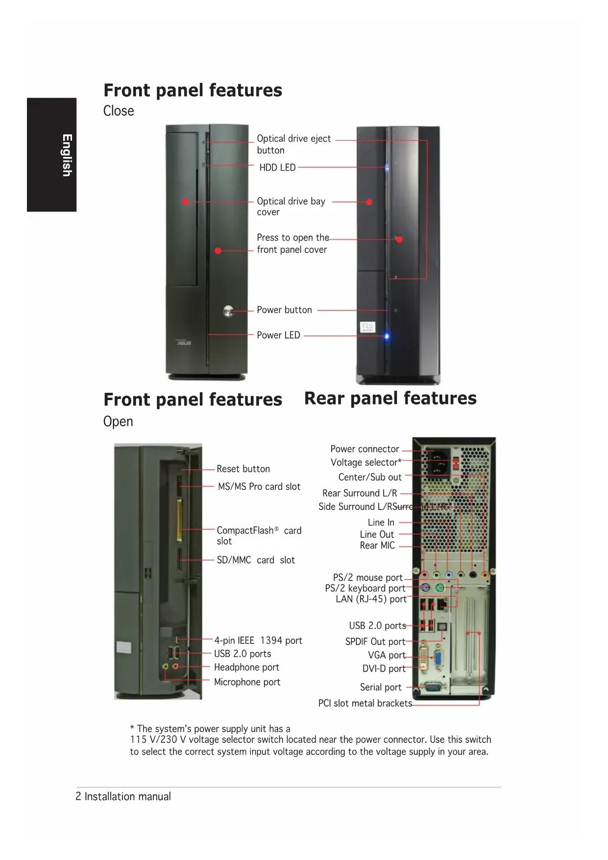
natural_image
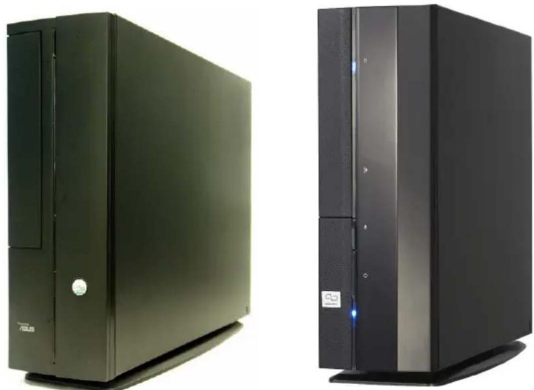
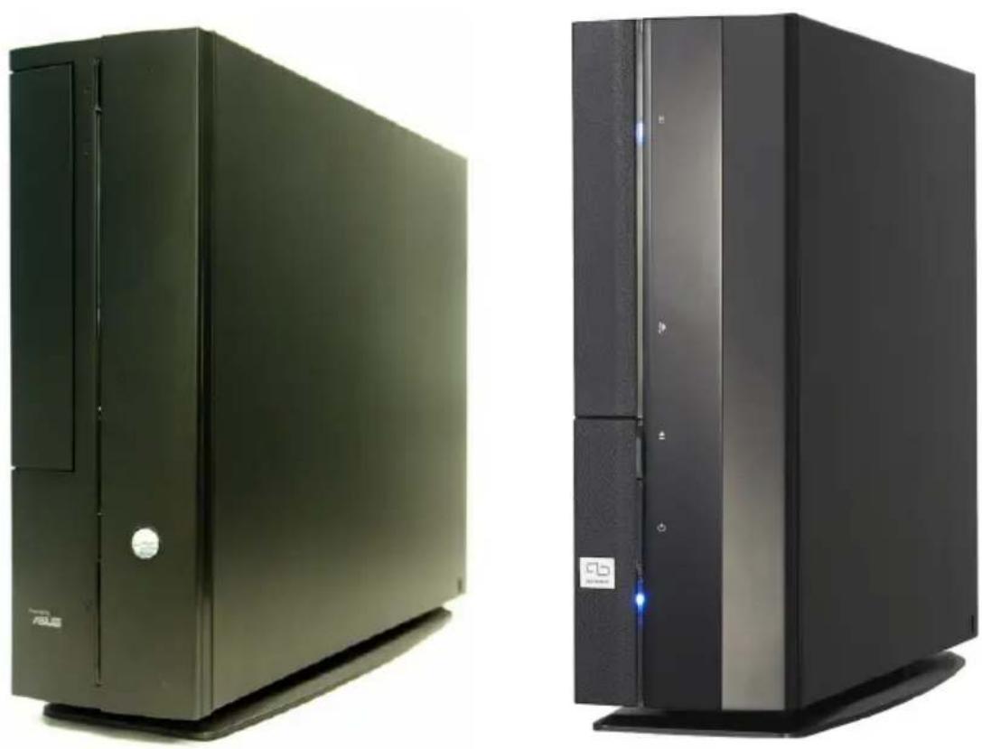
Two black desktop computer units, one with a visible logo and the other with a logo and control panel (no text or symbols on the devices themselves)Download the latest manual from the ASUS website: www.asus.com
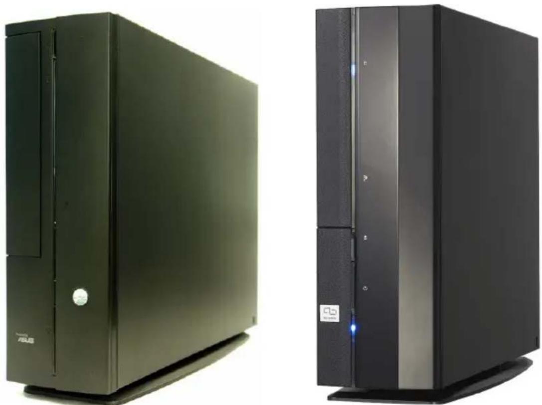
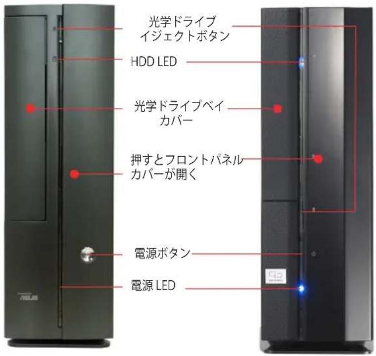
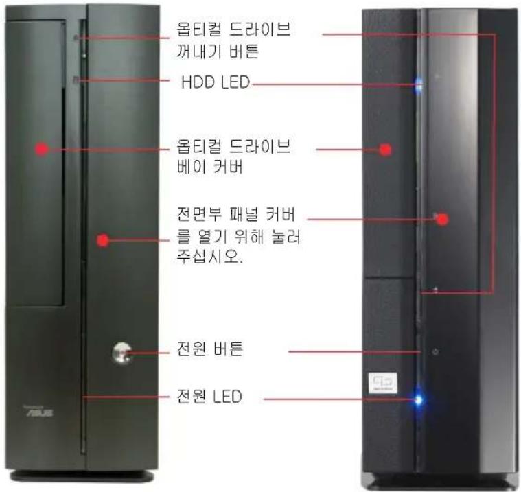
Front panel features
Close
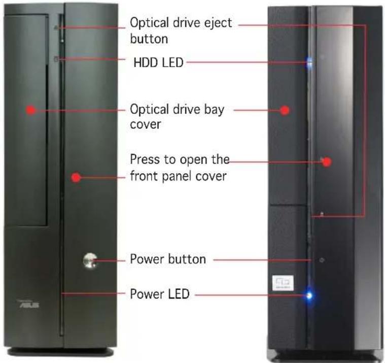
Front panel features Rear panel features
Open
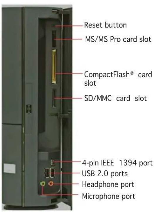

* The system's power supply unit has a 115 V/230 V voltage selector switch located near the power connector. Use this switch to select the correct system input voltage according to the voltage supply in your area.
Internal components
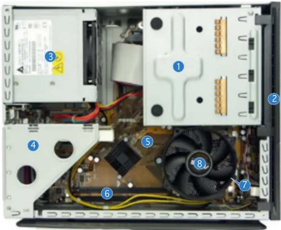
- 5.25-inch optical drive and 3.5 inch hard disk drive cage
- Front panel cover
- Power supply unit
-
PCI card riser bracket (connected to the motherboard PCI slot)
-
ASUS motherboard
- DIMM sockets
- LGA775 socket (under the CPU fan and heatsink assembly)
- CPU fan and heatsink assembly
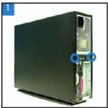
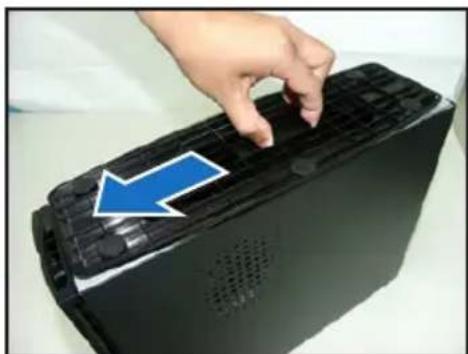
Removing the cover
- Remove the cover screws. Keep the screws for later use.
- Pull the cover slightly toward the rear panel.
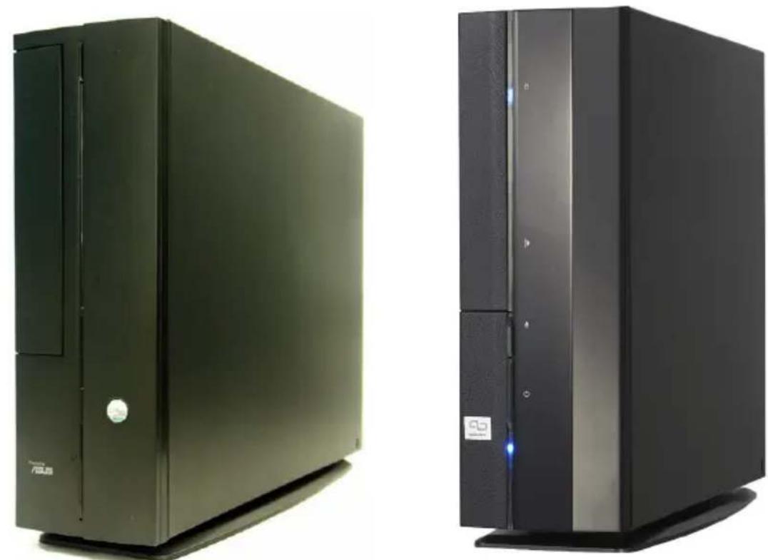
- Lift the cover, then set aside.
natural_image
Back view of a black server rack unit with ports and connectors (no visible text or labels)
natural_image
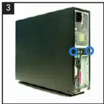
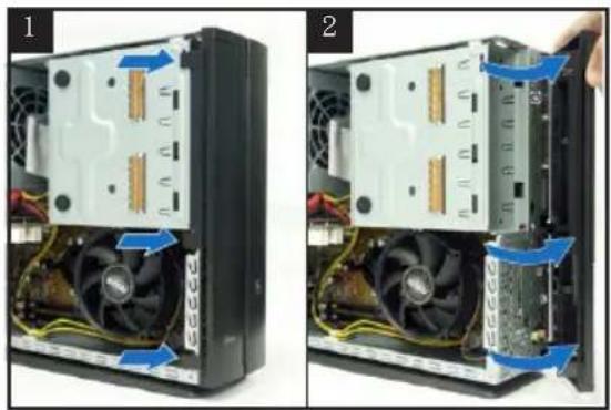
Hand pressing a button on a server rack, showing a blue arrow indicating motion (no text or symbols present)
natural_image
Hand holding a black device with a blue upward arrow on its cover, next to an open rear panel (no text or symbols visible)Removing the front panel cover
- Lift the front panel cover hooks outward.
- Carefully remove the front panel cover, then set it aside.

natural_image
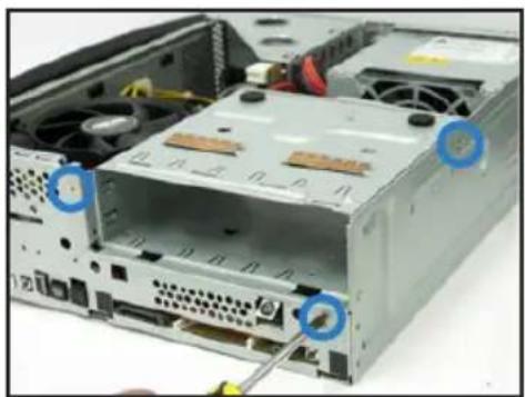
Two-panel photo showing a computer tower with visible CPU socket and fan blades, no text or symbols present.Removing the storage drive assembly
-
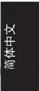
Lay the system on its side, then locate and remove three storage drive assembly screws.
-
Lift the storage drive assembly, then set aside.
natural_image
Interior view of a computer drive bay showing internal components and a cable inserted (no text or symbols visible)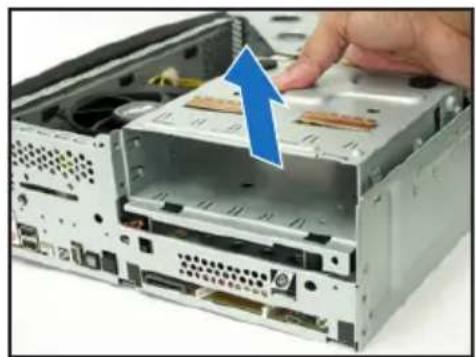
natural_image
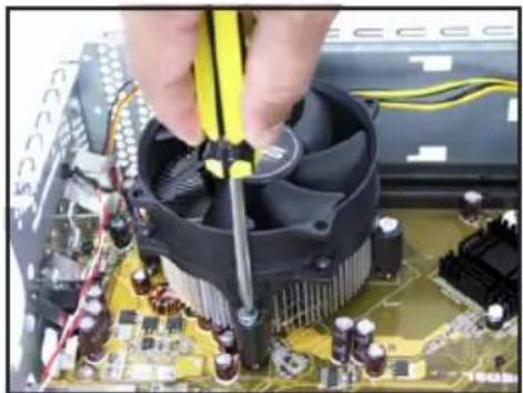
Close-up of a computer drive showing internal components and a hand inserting a component (no text or symbols visible)Removing the CPU fan and heatsink
- Disconnect the CPU fan cable.
-
Loosen the CPU fan and heatsink assembly screws.
-
Lift the CPU fan and heatsink assembly, then set aside.
natural_image
Close-up of hands working on a computer motherboard with a CPU socket and power cord (no visible text or symbols)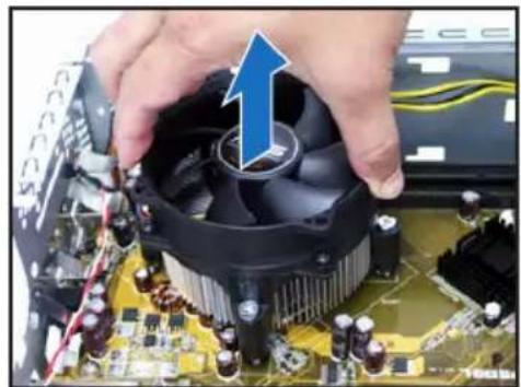
natural_image
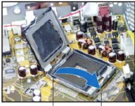
Close-up of hands holding a CPU fan on a motherboard with visible circuitry and components (no text or symbols)Installing the CPU
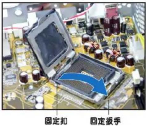
- Unlock the load lever, then lift to a 90^-100^ angle.
natural_image
Close-up of a computer motherboard with an open processor and a blue arrow indicating a process or component (no visible text or symbols)Load leverRetention tab
- Lift the load plate, then remove the PnP cap.

natural_image
Close-up of a computer motherboard with a hand holding an open CPU socket and a blue arrow indicating the process (no text or symbols visible)-
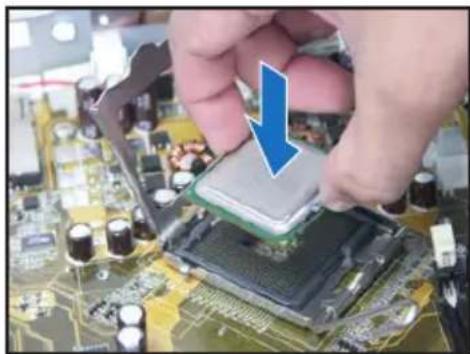
Install the CPU. The CPU fits in only one orientation.
-
Close the load plate, then lock the load lever.
natural_image
Close-up of hands installing a chip onto a computer motherboard with a blue arrow indicating the process (no text or symbols visible)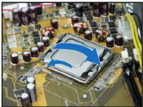
natural_image
Close-up of a computer motherboard with visible CPU socket and surrounding components (no text or symbols)- Reinstall the CPU fan and heatsink assembly, then reconnect the CPU fan cable to the CPU fan connector on the motherboard. Refer to the instructions in the previous section for details.
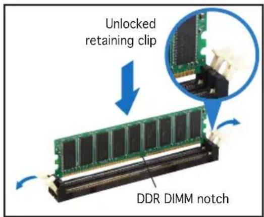
Installing a DIMM
- Locate the DIMM sockets in the motherboard.
- Unlock a DIMM socket by pressing the retaining clips outward.
- Align a DIMM on the socket such that the notch on the DIMM matches the break on the socket.
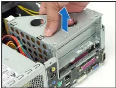
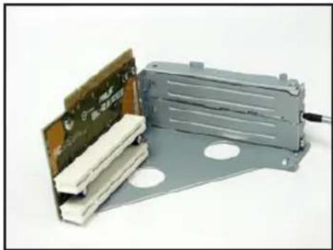
Installing an expansion card
- Lift the PCI riser card assembly to remove.
natural_image
Close-up of a computer tower case with a hand pressing a button, showing internal components and wiring (no text or symbols visible)-
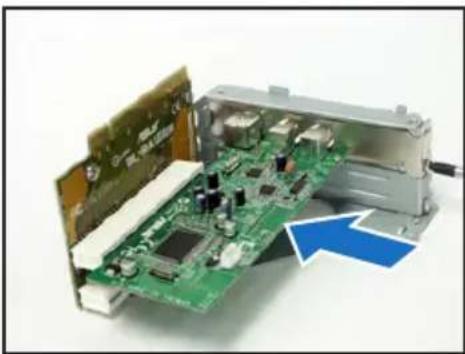
Insert the card connector to the slot, then press the card firmly until it fits in place. Secure the card with a screw.
-
Remove the metal cover opposite the slot that you intend to use.
natural_image
Electronic component with circuit board and metallic housing, no visible text or symbols- Reinstall the PCI riser card assembly. Make sure that the riser card connector sits properly on the motherboard PCI slot.
natural_image
Interior view of an electronic device showing a green circuit board with internal components and a blue arrow pointing to a component (no text or symbols visible)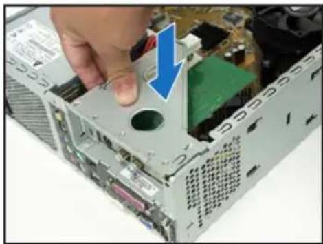
natural_image
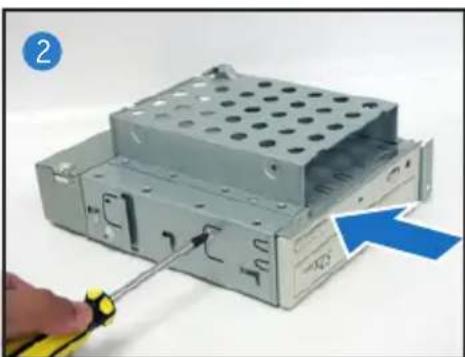
Close-up of a computer tower case with a hand inserting a component, showing internal circuitry and a blue arrow indicating the direction (no text or symbols visible)Installing optical and storage drives
- Turn the storage drive assembly upside down with the 3.5-inch bay on top of the 5.25-inch bay.
- Insert the optical drive upside down to the 5.25-inch bay, then secure it with two screws on both sides.
- Turn the storage drive assembly, insert the hard disk drive upside down to the 3.5-inch bay, then secure it with two screws on both sides.
natural_image
Close-up of a computer hard drive with a screwdriver inserted, showing internal components and a blue arrow indicating the component (no text or symbols present)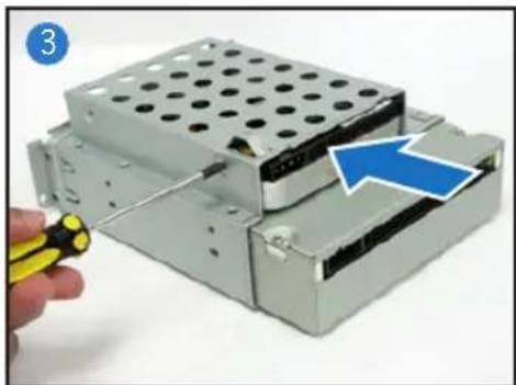
natural_image
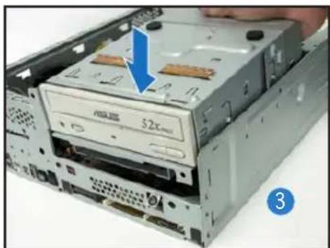
Hand holding a yellow pen next to a stacked electronic device with a blue arrow pointing to a component (no text or symbols visible)Reinstalling the storage drive assembly
Before reinstalling the storage drive assembly, connect the IDE/SATA and power plugs to the IDE/SATA and power connectors at the back of the drives.
- Connect the black plug of the IDE cable to the optical drive, then the gray plug to the hard disk drive. If you have the SATA HDD, connect the SATA cable to the SATA HD.
- Connect the 4-pin power plugs to the power connectors at the back of the drives.
- Install the storage drive assembly to the chassis.
- Secure the storage drive assembly with three screws.
natural_image
Close-up of a CD-ROM drive showing internal components and a blue arrow pointing to the top portion (no text or symbols on the device itself)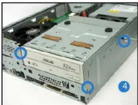
natural_image
Interior view of a computer drive chassis showing CPU socket, drive bays, and ventilation slots (no text or symbols visible)Installing the foot stand
- Match the foot stand hooks to the holes on the chassis.
natural_image
Hand placing a folder into a computer tower case with a blue arrow indicating the direction (no text or symbols visible)- Pull the foot stand to the direction of the arrow until the lock clicks in place.
natural_image
Hand pressing down on a black electronic device with a blue arrow pointing to the button (no text or symbols visible)To remove the foot stand, lift the lock, then slightly push the foot stand to the direction of the rear panel until it disengages from the chassis.
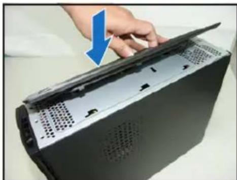
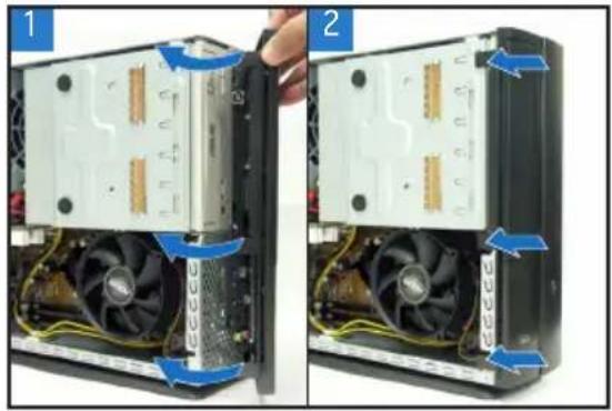
Reinstalling the front panel cover
- Insert the front panel cover tabs to the holes at the right side of the chassis, then close.
- Insert the front panel cover hooks to the chassis tabs until the front panel cover fits in place.
natural_image
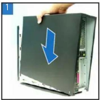
Two-panel photo showing a computer tower with visible CPU socket and heatsink, labeled 1 and 2 (no text or symbols on the diagram itself)Reinstalling the cover
- Install the cover to the chassis. Make sure the cover tabs fit the chassis rails.
- Push the cover toward the front panel until it fits in place.
- Secure the cover with two screws.
natural_image
Hand holding a black computer tower with a blue downward arrow on its cover (no text or symbols visible)
natural_image
Hand holding a black server rack with a blue arrow pointing to the side panel (no text or symbols visible)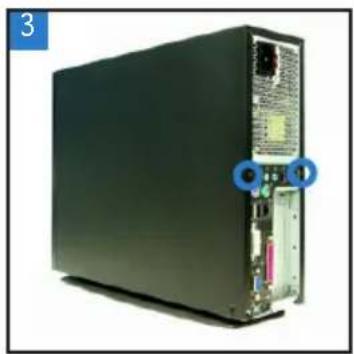
natural_image
Front view of a black server rack with ports and connectors, no visible text or symbolsP1-P5945G/P2-P5945G
natural_image
Two black desktop computer units, one front and one side, displayed against a white background (no visible text or symbols)natural_image
Front view of a server rack unit with visible ports and connectors (no text or symbols)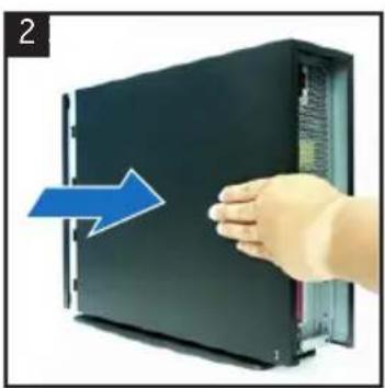
natural_image
Hand pressing a button on a black server rack, with a blue arrow indicating the motion (no text or symbols visible)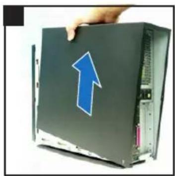
natural_image
Hand holding a computer monitor with a blue upward arrow on the cover (no text or symbols visible)natural_image
Two views of a computer tower showing internal CPU socket and drive mechanism (no text or symbols visible)natural_image
Interior view of a computer drive bay showing internal components and a screwdriver inserted (no text or symbols visible)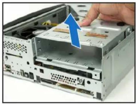
natural_image
Close-up of a computer drive showing a CD-ROM with an open rear case and a hand inserting a cable into it (no text or symbols visible)natural_image
Close-up of hands using a power tool to adjust the CPU into a motherboard (no visible text or symbols)
natural_image
Close-up of hands holding a CPU fan on a motherboard with visible circuitry and components (no text or symbols)Installer un CPU
natural_image
Close-up of a computer motherboard with visible electronic components and a blue arrow indicating a process or change (no text or symbols)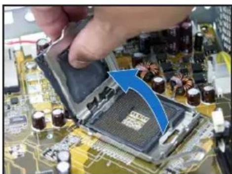
natural_image
Close-up of a computer motherboard with a hand holding an open CPU socket and a blue arrow indicating the process (no visible text or symbols)natural_image
Close-up of hands installing a microchip on a circuit board with a blue arrow indicating the component (no text or symbols visible)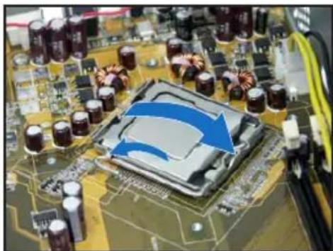
natural_image
Close-up of a computer motherboard with a highlighted CPU socket and surrounding components (no visible text or symbols)natural_image
Close-up of a computer tower case with a hand pressing down on the cover (no visible text or labels)natural_image
Electronic component with exposed circuit board and metallic housing (no visible text or symbols)natural_image
Interior view of an electronic device showing a green circuit board with internal components and a blue arrow indicating a component (no text or symbols visible)
natural_image
Close-up of a computer tower case with a hand inserting a component, showing internal circuitry and a blue arrow indicating the process (no text or symbols visible)natural_image
Close-up of a computer drive chassis with a screwdriver inserted, showing internal components and a blue arrow indicating direction (no text or symbols)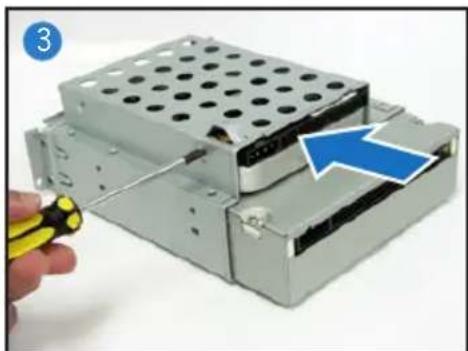
natural_image
Hand holding a yellow tool next to a stacked electronic device with a blue arrow pointing to a component (no text or symbols visible)natural_image
Interior view of a computer drive showing external components and labeled ports (no readable text or symbols)Installer le pied de support
natural_image
Close-up of a hand opening a computer case with a blue arrow pointing to the lid (no text or symbols visible)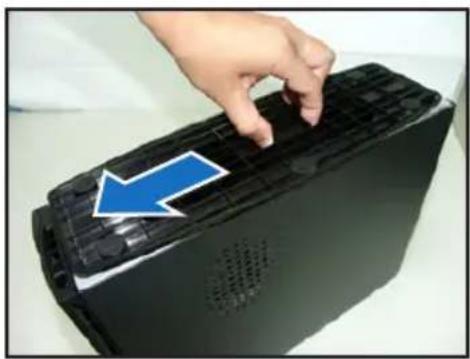
natural_image
Hand pressing down on a black electronic device with a blue arrow pointing to the button (no text or symbols visible)natural_image
Two views of a computer tower showing internal CPU socket and drive mechanism (no text or symbols visible)natural_image
Hand holding a black server case with a blue downward arrow on its side, next to an open drive (no text or symbols visible)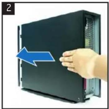
natural_image
Hand pressing a black server rack with a blue arrow indicating left motion (no text or symbols)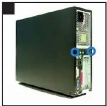
natural_image
Front view of a black server rack with ports and connectors (no visible text or labels)ASUS
P1-P5945G/P2-P5945G
華碩個人電腦(桌上型準系統)
安裝手冊
natural_image
Two desktop computer units shown from front and side views, one green and one black, with no visible text or labels.natural_image
Back view of a server rack unit with ports and connectors (no visible text or labels)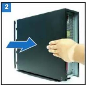
natural_image
Hand inserting a device into a rack, showing a blue arrow indicating direction (no text or symbols present)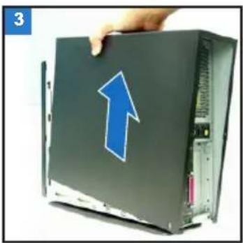
natural_image
Hand holding a computer hard drive with a blue upward arrow on the cover (no text or symbols visible)移除前面板
- 將前面板左側的三個固定卡榫往外扳開。
natural_image
Two-panel photo showing a computer tower with visible CPU socket and fan blades, no text or symbols present.移除儲存裝置模組
natural_image
Interior view of a computer drive bay with visible ports and screwdriver (no text or symbols)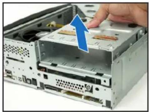
natural_image
Close-up of a computer drive showing internal components and a hand inserting a component (no text or symbols visible)移除 CPU 風扇
natural_image
Close-up of hands using a tool to adjust a CPU fan on a motherboard (no visible text or symbols)
natural_image
Close-up of hands holding a computer CPU socket with an upward arrow indicating rotation (no text or symbols visible)安裝 CPU
natural_image
Close-up of a computer motherboard with a hand holding an open CPU socket and a blue arrow indicating the process (no text or symbols visible)natural_image
Close-up of hands installing a microchip on a circuit board with a blue arrow indicating the component (no text or symbols visible)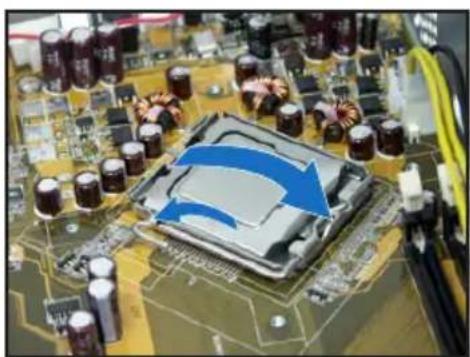
natural_image
Close-up of a computer motherboard with a highlighted CPU socket and surrounding capacitors (no visible text or symbols)
natural_image
Close-up of a computer tower case with a hand pressing a button, showing internal components and wiring (no text or symbols visible)natural_image
Electronic component with circuit board and metallic housing, no visible text or symbolsnatural_image
Interior view of an electronic device showing a green circuit board with internal components and a blue arrow pointing to a component (no text or symbols visible)
natural_image
Close-up of a computer tower case with a hand inserting a component, showing internal circuitry and a blue arrow indicating the direction (no text or symbols visible)安裝光碟機及硬碟機
natural_image
Close-up of a computer drive chassis with a hand using a screwdriver to adjust internal components (no text or symbols visible)
natural_image
Hand holding a yellow pen next to a stacked electronic device with a blue arrow pointing to a component (no text or symbols visible)裝回儲存裝置模組
natural_image
Close-up of a computer drive showing CD52 drive with a blue arrow pointing to the component (no text or symbols visible)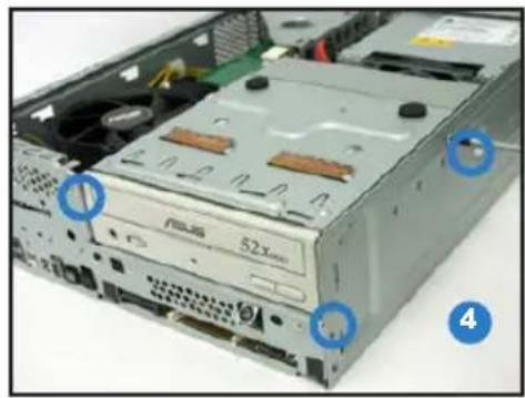
natural_image
Interior view of a computer drive bay showing rear-mounted drive and ventilation slots (no text or symbols visible)安裝腳座
natural_image
Close-up of a hand opening a computer case with a blue arrow pointing to the lid (no text or symbols visible)
natural_image
Hand pressing down on a black electronic device with a blue arrow pointing to the button (no text or symbols visible)natural_image
Hand holding a black server case with a blue downward arrow, no visible text or symbols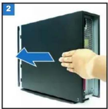
natural_image
Hand holding a black server rack with a blue arrow pointing to the side panel (no text or symbols visible)
natural_image
Front view of a black server rack with ports and connectors, no visible text or symbolsASUS
P1-P5945G/P2-P5945G
华硕个人电脑(桌上型准系统)
安装手册
natural_image
Two black desktop computer units shown from front and side views, no visible text or labels on the devices themselves.natural_image
Back view of a server rack unit with visible ports and connectors (no text or symbols)
natural_image
Hand pressing a device into a rack, showing a blue arrow indicating motion (no text or symbols present)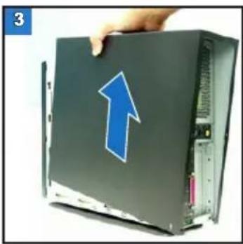
natural_image
Hand holding a black hard drive with a blue upward arrow on top (no text or symbols visible)去除前面板除前面板
- 将前面板左侧的三个固定卡榫往外扳开。

natural_image
Two-panel photo showing a computer tower with visible CPU socket and fan blades, no text or symbols present.去除存储设备模块
natural_image
Interior view of a computer drive bay with visible ports and screwdrivers (no text or symbols)
natural_image
Close-up of a computer drive showing a hand inserting a CD into a motherboard (no text or symbols visible)去除 CPU 风扇
natural_image
Close-up of hands working on a computer motherboard with a CPU socket and heatsink (no visible text or symbols)
natural_image
Close-up of hands holding a CPU socket with an upward arrow indicating motion (no text or symbols visible)安装 CPU
- 将固定扳手扳开至90-100度。
natural_image
Close-up of a computer motherboard with a hand inserting a component into the chip (no visible text or symbols)natural_image
Close-up of hands installing a microchip on a circuit board with a blue arrow indicating the component (no text or symbols visible)
natural_image
Close-up of a computer motherboard with visible CPU socket and surrounding components (no text or symbols)- 装回 CPU 风扇并接回风扇电源线。请参考前面小节的说明。装回 CPU 风扇并接回风扇
安装内存条内存条
natural_image
Close-up of a computer tower drive with a hand pressing a button, showing internal components and cable (no text or symbols visible)
natural_image
Electronic component with circuit board and metallic housing, no visible text or symbolsnatural_image
Interior view of an electronic circuit board with exposed components and a blue arrow indicating a component (no text or symbols visible)
natural_image
Close-up of a computer tower case with a hand inserting a component, showing internal circuitry and a blue arrow indicating the direction (no text or symbols visible)安装光驱及硬盘光驱及硬盘
natural_image
Close-up of a computer drive chassis with a hand using a screwdriver to adjust internal components (no text or symbols visible)
natural_image
Close-up of a computer hard drive with a hand holding a yellow pen, showing internal components and a blue arrow indicating a component (no text or symbols present)装回存储设备模块存储设备模块
natural_image
Close-up of a CD-ROM drive with a blue arrow pointing to the disc (no text or symbols visible)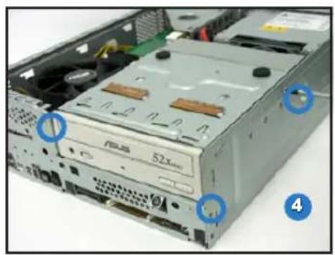
natural_image
Interior view of a computer drive bay showing rear-mounted drive and ventilation slots (no text or symbols visible)安装脚座
natural_image
Hand placing a device into a black computer case with ventilation slots, showing a blue arrow indicating the process (no text or symbols visible)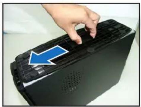
natural_image
Hand pressing down on a black electronic device with a blue arrow pointing to the button (no text or symbols visible)natural_image
Hand holding a computer tower with a blue downward arrow on the cover (no text or symbols visible)
natural_image
Hand holding a black server rack with a blue arrow pointing to the front panel (no text or symbols visible)
natural_image
Front view of a black server rack with visible ports and connectors (no text or symbols)ASUS
P1-P5945G/P2-P5945G
natural_image
Two black desktop computer units shown from front and side views, one with a visible logo on the left (no text or symbols on the device itself)フロントパネル
閉じた状態
natural_image
Front view of a black server rack with visible ports and connectors (no text or symbols)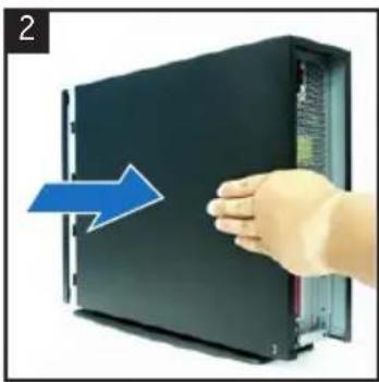
natural_image
Hand pressing a black server rack with a blue arrow indicating leftward motion (no text or symbols)
natural_image
Hand holding a black hard drive with a blue upward arrow on top (no text or symbols visible)フロントパネルカバーを取り外す
natural_image
Two-panel photo showing a computer tower with visible CPU socket and internal components, no text or symbols present.記憶ドライブを取り外す
natural_image
Interior view of a computer drive bay showing internal components and a cable inserted (no visible text or labels)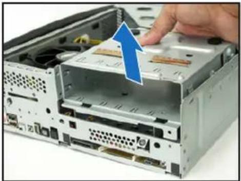
natural_image
Interior view of a computer drive showing a CD expansion with a blue arrow indicating the process (no text or symbols visible)CPUファンとヒートシンクを取り外す
natural_image
Close-up of a CPU motherboard with a hand adjusting the heatsink and screwdriver (no visible text or symbols)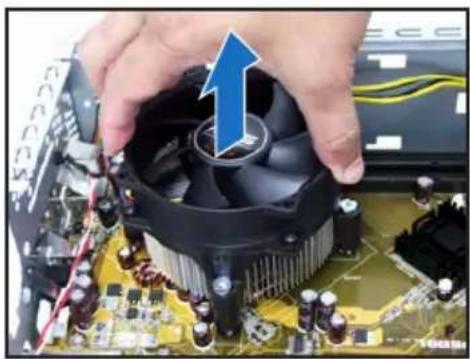
natural_image
Close-up of hands holding a CPU socket with a blue arrow pointing to the top panel (no visible text or symbols)CPU の取付け
natural_image
Close-up of a computer motherboard with a highlighted CPU socket and blue arrow indicating a process (no text or symbols present)受け側のツメ
natural_image
Close-up of a computer motherboard with a hand holding an open CPU socket, showing internal components and a blue arrow indicating the process (no text or symbols visible)natural_image
Close-up of hands installing a microchip on a circuit board with a blue arrow indicating the component (no text or symbols visible)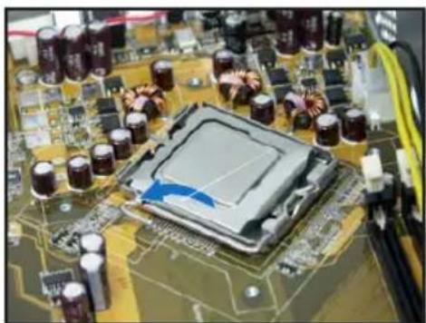
natural_image
Close-up of a computer motherboard with visible CPU socket and surrounding components (no text or symbols)natural_image
Close-up of a computer tower case with a hand inserting a component, showing internal wiring and drive slots (no text or symbols visible)natural_image
Electronic component with a circuit board and metallic housing, no visible text or symbolsnatural_image
Interior view of an electronic circuit board with exposed components and a blue arrow indicating direction (no text or symbols)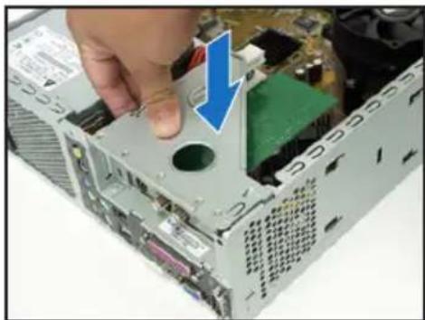
natural_image
Close-up of a computer tower case with a hand inserting a component, showing internal components and a blue arrow indicating the direction (no text or symbols present)光学ドライブと記憶ドライブを取り付ける
natural_image
Close-up of a computer drive with a screwdriver inserted, showing internal components and a blue arrow indicating motion (no text or symbols)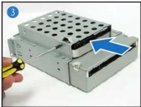
natural_image
Hand holding a yellow pen next to a stacked electronic device with a blue arrow pointing to a component (no text or symbols visible)記憶ドライブを再び取り付ける
natural_image
Close-up of an open CD-ROM drive showing internal components and a blue arrow pointing to a component labeled '52x' (no readable text beyond label)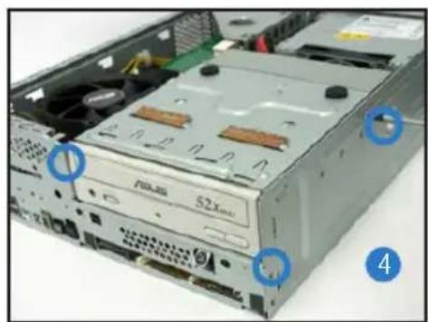
natural_image
Interior view of a computer drive bay showing power spool and drive casing (no text or symbols visible)フットスタンドを取り付ける
natural_image
Close-up of a hand holding a computer case with a blue arrow pointing to the lid (no text or symbols visible)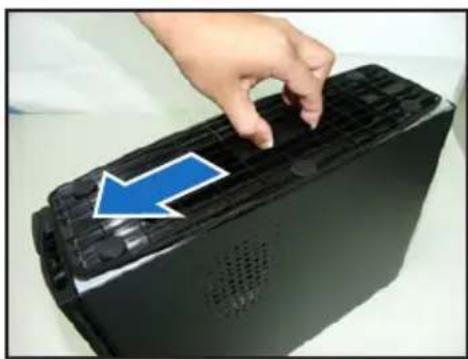
natural_image
Hand pressing down on a black electronic device with a blue arrow pointing to the button (no text or symbols visible)natural_image
Two-panel photo showing a computer tower with visible CPU socket and internal components, no text or symbols present.カバーを再び取り付ける
natural_image
Hand holding a computer tower with a blue downward arrow on the cover (no text or symbols visible)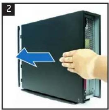
natural_image
Hand holding a black server rack with a blue arrow pointing to the side panel (no text or symbols visible)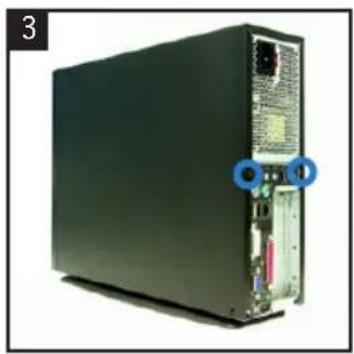
natural_image
Front view of a black server rack with visible ports and connectors (no text or symbols)ASUS
P1-P5945G/P2-P5945G
ASUS PC (데스크탑 베어본)
빠른 설치 가이드
natural_image
Two black desktop computer units, one with a visible logo and the other with a logo and control panel (no text or symbols on the devices themselves)전면부 사양
닫힌 상태
natural_image
Back view of a black server rack unit with ports and connectors (no visible text or labels)
natural_image
Hand inserting a device into a server rack, showing a blue arrow indicating the direction (no text or symbols present)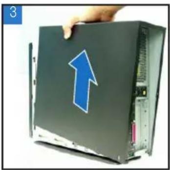
natural_image
Hand holding a computer case with a blue upward arrow on the cover (no text or symbols visible)전면부 패널 제거
natural_image
Two-panel photo showing a computer tower with visible CPU socket and fan, labeled 1 and 2 (no text or symbols on the diagram itself)저장 장치 드라이브 제거
natural_image
Interior view of a computer drive bay with cooling fans and drive bays, showing no visible text or symbolsnatural_image
Close-up of a computer drive showing internal components and a hand inserting a component (no text or symbols visible)CPU 팬과 핓 싱크 제거
natural_image
Close-up of hands installing a CPU into a motherboard with visible cooling fans and circuit board (no text or symbols)natural_image
Close-up of hands holding a CPU fan on a motherboard with visible circuitry and components (no text or symbols)CPU 설치
natural_image
Close-up of a computer motherboard with a disassembled chip and surrounding electronic components (no visible text or symbols)natural_image
Close-up of a hand holding an open electronic circuit board with visible components and a blue arrow indicating a component (no text or symbols)로드 레버리텐션 탑
natural_image
Close-up of hands installing a microchip on a computer motherboard, with a blue arrow indicating the component (no text or symbols visible)
natural_image
Close-up of a computer motherboard with a highlighted CPU socket and surrounding components (no visible text or symbols)natural_image
Close-up of a computer tower case with a hand inserting a component, showing internal structure and cable (no text or symbols visible)natural_image
Electronic component with circuit board and metal housing, no visible text or symbolsnatural_image
Interior view of an electronic device showing a green circuit board with internal components and a blue arrow indicating a component (no text or symbols visible)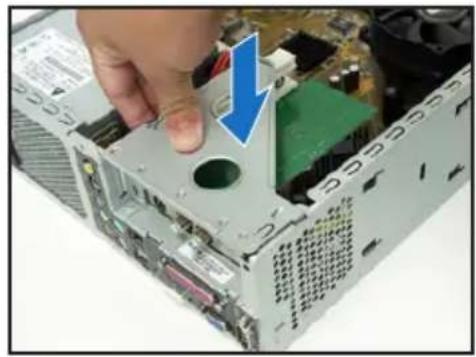
natural_image
Close-up of a computer motherboard showing a hand inserting a component into a drive casing (no visible text or labels)옵티컬 & 저장 장치 드라이브 설치
natural_image
Close-up of a computer hard drive with a screwdriver inserted, showing internal components and a blue arrow indicating direction (no text or symbols)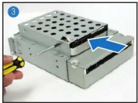
natural_image
Close-up of a mechanical device with a hand holding a yellow tool, showing internal components and a blue arrow indicating a specific component (no text or symbols visible)저장 장치 드라이브 재설치
natural_image
Close-up of a computer drive chassis showing internal components and mounting holes (no text or symbols visible)풋 스탠드 설치
natural_image
Close-up of a hand opening a computer case with a blue arrow pointing to the lid (no text or symbols visible)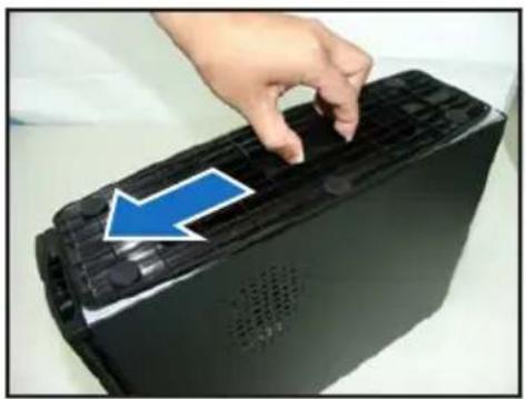
natural_image
Hand pressing down on a black electronic device with a blue arrow pointing to the button (no text or symbols visible)natural_image
Two-panel photo showing a computer tower with visible CPU socket and drive, labeled 1 and 2 (no text or symbols on the diagram itself)커버 재설치
natural_image
Hand holding a computer tower with a blue downward arrow pointing to the front panel (no text or symbols visible)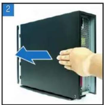
natural_image
Hand holding a black server rack with a blue arrow pointing to the front panel (no text or symbols visible)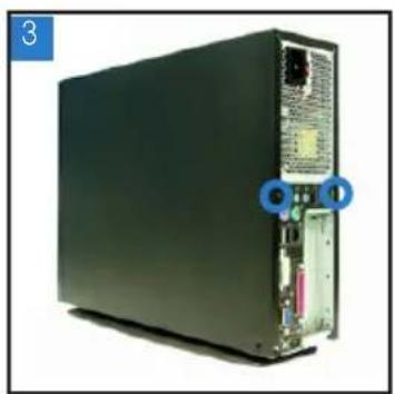
natural_image
Front view of a black server rack with ports and connectors (no visible text or symbols)P1-P5945G/P2-P5945G
ASUS PC
natural_image
Two black desktop computer units, one front and one side, displayed against a white background (no visible text or symbols)natural_image
Front view of a black server rack unit with visible ports and connectors (no text or symbols)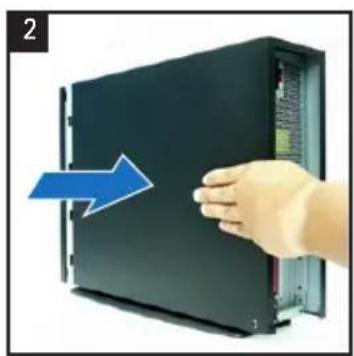
natural_image
Hand pressing a button on a black server rack, with a blue arrow indicating the direction (no text or symbols visible)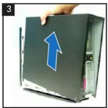
natural_image
Hand holding a computer drive with a blue upward arrow on the cover (no text or symbols visible)natural_image
Two-panel photo showing a computer tower with visible CPU socket and internal components, no text or symbols present.natural_image
Interior view of a computer drive bay showing internal components and ventilation slots (no text or symbols visible)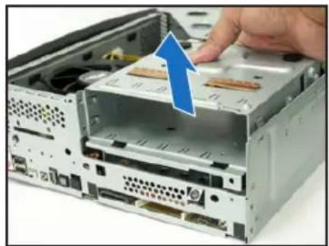
natural_image
Close-up of a computer drive showing internal components and a hand inserting a component (no text or symbols visible)natural_image
Close-up of hands using a computer to adjust the CPU into a motherboard (no visible text or symbols)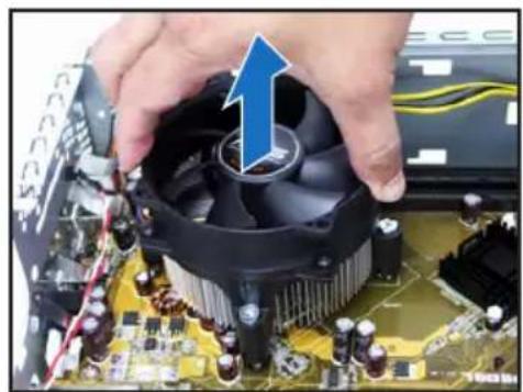
natural_image
Close-up of hands holding a CPU fan on a motherboard, with a blue arrow indicating the component (no visible text or symbols)CPU'nun takılması
natural_image
Close-up of an open circuit board with a disassembled chip and surrounding components (no visible text or symbols)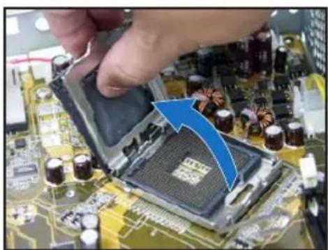
natural_image
Close-up of a computer motherboard with a hand holding a partially open CPU socket and a blue arrow indicating the process (no text or symbols visible)natural_image
Close-up of hands holding a CPU socket on a circuit board, with a blue arrow pointing to the component (no visible text or symbols)
natural_image
Close-up of a computer motherboard with visible CPU socket and surrounding components (no text or symbols)natural_image
Close-up of a computer tower case with a hand pressing down on the cover (no visible text or labels)natural_image
Interior view of an electronic circuit board with exposed components and a blue arrow indicating direction (no text or symbols)natural_image
Electronic component with exposed circuit board and metallic housing (no visible text or symbols)natural_image
Close-up of a computer tower case with a hand inserting a component, showing internal components and a blue arrow indicating the direction (no text or symbols present)natural_image
Close-up of a computer hard drive with a screwdriver inserted, showing internal components and a blue arrow pointing to the component (no text or symbols visible)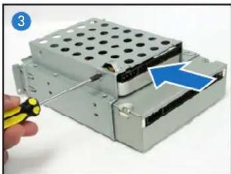
natural_image
Close-up of a mechanical assembly with a hand holding a yellow tool, showing internal components and a blue arrow indicating a specific part (no text or symbols present)natural_image
Close-up of a CD-ROM drive showing internal components and a blue arrow pointing to a component labeled '52x', with no visible text or symbols beyond the label.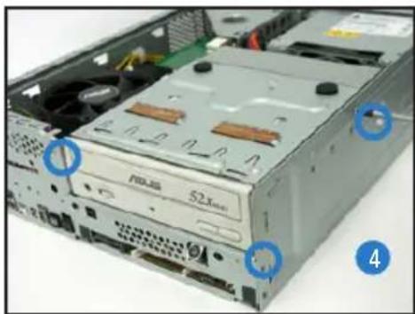
natural_image
Close-up of a computer tower drive showing internal components and ventilation slots (no readable text or symbols)natural_image
Close-up of a computer tower with a hand holding the lid, showing ventilation slots and ventilation grilles (no text or symbols visible)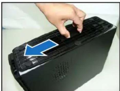
natural_image
Hand pressing down on a black electronic device with a blue arrow pointing to the lid (no text or symbols visible)natural_image
Two-panel photo showing a computer tower with visible CPU socket and cooling fan, no text or symbols present.natural_image
Hand holding a computer monitor with a blue downward arrow on the cover (no text or symbols visible)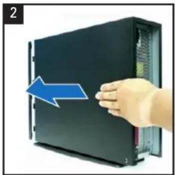
natural_image
Hand pressing a black server rack with a blue arrow indicating leftward motion (no text or symbols)