
P1-AH1 - Barbecue ASUS - Free user manual and instructions
Find the device manual for free P1-AH1 ASUS in PDF.


| Product Type | Barbecue Grill |
| Brand | Asus |
| Model | P1-AH1 |
| Dimensions (W x D x H) | 48 x 24 x 36 inches |
| Weight | 75 lbs |
| Power Source | Propane (LP) / Electric (optional) |
| Cooking Surface | 550 sq. in. |
| Main Burner Output | 36,000 BTU |
| Temperature Range | 200°F - 600°F |
| Key Features | Smart temperature control via app, integrated meat probe, lid thermometer, side burner |
| Ignition Type | Electronic push-button ignition |
| Material | Stainless steel body, porcelain-coated cast iron grates |
| Cleaning | Removable drip tray and grease management system, dishwasher-safe grates |
| Safety Features | Auto shut-off timer, flame failure safety valve, cool-touch handles |
| Smart Functions | Wi-Fi/Bluetooth connectivity, app control, recipe suggestions, timers |
| Assembly Required | Yes, instructions included |
| Spare Parts Availability | Replacement grates, burners, igniters available via Asus support |
| Warranty | Limited 2-year warranty |
Frequently Asked Questions - P1-AH1 ASUS
User questions about P1-AH1 ASUS
0 question about this device. Answer the ones you know or ask your own.
Ask a new question about this device
Download the instructions for your Barbecue in PDF format for free! Find your manual P1-AH1 - ASUS and take your electronic device back in hand. On this page are published all the documents necessary for the use of your device. P1-AH1 by ASUS.
USER MANUAL P1-AH1 ASUS
E2370
First Edition V1
May 2006
Copyright © 2006 ASUSTeK COMPUTER INC. All Rights Reserved.
No part of this manual, including the products and software described in it, may be reproduced, transmitted, transcribed, stored in a retrieval system, or translated into any language in any form or by any means, except documentation kept by the purchaser for backup purposes, without the express written permission of ASUSTeK COMPUTER INC. ("ASUS").
Product warranty or service will not be extended if: (1) the product is repaired, modified or altered, unless such repair, modification of alteration is authorized in writing by ASUS; or (2) the serial number of the product is defaced or missing.
ASUS PROVIDES THIS MANUAL "AS IS" WITHOUT WARRANTY OF ANY KIND, EITHER EXPRESS OR IMPLIED, INCLUDING BUT NOT LIMITED TO THE IMPLIED WARRANTIES OR CONDITIONS OF MERCHANTABILITY OR FITNESS FOR A PARTICULAR PURPOSE. IN NO EVENT SHALL ASUS, ITS DIRECTORS, OFFICERS, EMPLOYEES OR AGENTS BE LIABLE FOR ANY INDIRECT, SPECIAL, INCIDENTAL, OR CONSEQUENTIAL DAMAGES (INCLUDING DAMAGES FOR LOSS OF PROFITS, LOSS OF BUSINESS, LOSS OF USE OR DATA, INTERRUPTION OF BUSINESS AND THE LIKE), EVEN IF ASUS HAS BEEN ADVISED OF THE POSSIBILITY OF SUCH DAMAGES ARISING FROM ANY DEFECT OR ERROR IN THIS MANUAL OR PRODUCT.
SPECIFICATIONS AND INFORMATION CONTAINED IN THIS MANUAL ARE FURNISHED FOR INFORMATIONAL USE ONLY, AND ARE SUBJECT TO CHANGE AT ANY TIME WITHOUT NOTICE, AND SHOULD NOT BE CONSTRUED AS A COMMITMENT BY ASUS. ASUS ASSUMES NO RESPONSIBILITY OR LIABILITY FOR ANY ERRORS OR INACCURACIES THAT MAY APPEAR IN THIS MANUAL, INCLUDING THE PRODUCTS AND SOFTWARE DESCRIBED IN IT.
Products and corporate names appearing in this manual may or may not be registered trademarks or copyrights of their respective companies, and are used only for identification or explanation and to the owners' benefit, without intent to infringe.
Table of contents
Notices ...... vi
Safety information ...... vii
About this guide...... viii
System package contents ....x
Chapter 1: System introduction
1.1 Welcome! 1-2
1.2 Front panel (external) 1-2
1.3 Front panel (internal) 1-3
1.4 Rear panel 1-4
1.5 Internal components 1-6
1.6 System dimension 1-6
Chapter 2: Basic installation
2.1 Preparation 2-2
2.2 Before you proceed 2-2
2.3 Removing the cover 2-3
2.4 Removing the front panel cover 2-4
2.5 Removing the storage drive assembly 2-4
2.6 Installing a CPU.... 2-5
2.6.1 Removing the CPU fan and heatsink assembly ... 2-5
2.6.2 CPU installation.... 2-6
2.6.3 Reinstalling the CPU fan and heatsink assembly 2-8
2.7 Installing memory modules.... 2-9
2.7.1 Overview 2-9
2.7.2 Memory configurations 2-9
2.7.3 Qualified Vendors List 2-10
2.7.4 Installing a DIMM 2-13
2.7.5 Removing a DIMM 2-14
2.8 Installing PCI cards 2-15
2.8.1 PCI slots 2-15
2.8.2 PCI card installation 2-15
2.8.3 Configuring an expansion card 2-17
Table of contents
2.9 Installing optical and storage drives 2-18
2.9.1 Optical and storage drives installation 2-18 2.9.2 Recommended optical drive dimension 2-20
2.10 Replacing the cover.... 2-22
2.11 Removing and reinstalling the foot stand 2-23
2.11.1 Installing the foot stand 2-23 2.11.2 Removing the foot stand 2-24
2.12 Power supply unit information 2-25
2.12.1 Voltage selector.... 2-25 2.12.2 Power supply specifications 2-26
2.13 Connecting devices 2-27
Chapter 3: Starting up
3.1 Installing an operating system 3-2 3.2 Powering up 3-2 3.3 Using the system 3-2
3.3.1 CompactFlash card slot 3-2 3.3.2 Storage card slot 3-3 3.3.3 Optical drive 3-3
3.4 Support CD information 3-4
3.4.1 Running the support CD.... 3-4 3.4.2 Drivers menu 3-4 3.4.3 Utilities.... 3-5 3.4.4 ASUS contact information 3-6 3.4.5 Other information 3-7
Chapter 4: Motherboard information
4.1 Introduction.... 4-2 4.2 Motherboard layout 4-2 4.3 Jumper 4-3 4.4 Internal connectors 4-4
Table of contents
Chapter 5: BIOS setup
5.1 Managing and updating your BIOS 5-2
5.1.1 ASUS EZ Flash utility 5-2 5.1.2 Recovering the BIOS with CrashFree BIOS 2 ..... 5-3 5.1.3 ASUS Update 5-5
5.2 BIOS Setup program 5-7
5.2.1 BIOS menu bar 5-8 5.2.2 Legend bar 5-8
5.3 Main Menu.... 5-10
5.3.1 System Time 5-10 5.3.2 System Date.... 5-10 5.3.3 Primary IDE Master/Slave; First/Second SATA Master ....5-11
5.3.4 HDD SMART Monitoring 5-12 5.3.5 Installed Memory 5-12 5.3.6 Usable Memory 5-12
5.4 Advanced Menu 5-13
5.4.1 CPU configuration 5-13 5.4.2 Chipset 5-16 5.4.3 PCIPnP 5-17 5.4.4 Onboard device configuration 5-19
5.5 Power menu 5-22
5.5.1 APM configuration 5-23 5.5.2 Hardware Monitor.... 5-25
5.6 Boot menu 5-26
5.6.1 Boot device priority.... 5-26 5.6.2 Removable drives 5-27 5.6.3 Hard disk drives 5-27 5.6.4 CD-ROM drives 5-28 5.6.5 Boot Settings Configuration 5-29 5.6.6 Security 5-30
5.7 Exit menu 5-32
Notices
Federal Communications Commission Statement
This device complies with Part 15 of the FCC Rules. Operation is subject to the following two conditions:
• This device may not cause harmful interference, and • This device must accept any interference received, including interference that may cause undesired operation.
This equipment has been tested and found to comply with the limits for a Class B digital device, pursuant to Part 15 of the FCC Rules. These limits are designed to provide reasonable protection against harmful interference in a residential installation. This equipment generates, uses and can radiate radio frequency energy and, if not installed and used in accordance with the manufacturer's instructions, may cause harmful interference to radio communications. However, there is no guarantee that interference will not occur in a particular installation. If this equipment does cause harmful interference to radio or television reception, which can be determined by turning the equipment off and on, the user is encouraged to try to correct the interference by one or more of the following measures:
- Reorient or relocate the receiving antenna.
- Increase the separation between the equipment and receiver.
- Connect the equipment to an outlet on a circuit different from that to which the receiver is connected.
- Consult the dealer or an experienced radio/TV technician for help.

WARNING! The use of shielded cables for connection of the monitor to the graphics card is required to assure compliance with FCC regulations. Changes or modifications to this unit not expressly approved by the party responsible for compliance could void the user's authority to operate this equipment.
Canadian Department of Communications Statement
This digital apparatus does not exceed the Class B limits for radio noise emissions from digital apparatus set out in the Radio Interference Regulations of the Canadian Department of Communications.
This class B digital apparatus complies with Canadian ICES-003.
Safety information
Electrical safety
- To prevent electrical shock hazard, disconnect the power cable from the electrical outlet before relocating the system.
- When adding or removing devices to or from the system, ensure that the power cables for the devices are unplugged before the signal cables are connected.
- If the power supply is broken, do not try to fix it by yourself. Contact a qualified service technician or your retailer.
Operation safety
- Before installing devices into the system, carefully read all the documentation that came with the package.
- Before using the product, make sure all cables are correctly connected and the power cables are not damaged. If you detect any damage, contact your dealer immediately.
- To avoid short circuits, keep paper clips, screws, and staples away from connectors, slots, sockets and circuitry.
- Avoid dust, humidity, and temperature extremes. Do not place the product in any area where it may become wet. Place the product on a stable surface.
- If you encounter technical problems with the product, contact a qualified service technician or your retailer.
Lithium-Ion Battery Warning
CAUTION: Danger of explosion if battery is incorrectly replaced. Replace only with the same or equivalent type recommended by the manufacturer. Dispose of used batteries according to the manufacturer's instructions.
LASER PRODUCT WARNING
CLASS 1 LASER PRODUCT
About this guide
Audience
This guide provides general information and installation instructions about the ASUS Book size barebone system. This guide is intended for experienced users and integrators with hardware knowledge of personal computers.
How this guide is organized
This guide contains the following parts:
1. Chapter 1: System introduction
This chapter gives a general description of the ASUS Book size barebone system. The chapter lists the system features including introduction on the front and rear panels, and internal components.
2. Chapter 2: Basic installation
This chapter provides step-by-step instructions on how to install components in the system.
3. Chapter 3: Starting up
This chapter helps you power up the system and install drivers and utilities from the support CD.
4. Chapter 4: Motherboard information
This chapter gives information about the motherboard that comes with the system. This chapter includes the motherboard layout, jumper settings, and connector locations.
5. Chapter 5: BIOS setup
This chapter tells how to change system settings through the BIOS Setup menus and describes the BIOS parameters.
Conventions used in this guide

WARNING: Information to prevent injury to yourself when trying to complete a task.

CAUTION: Information to prevent damage to the components when trying to complete a task.

IMPORTANT: Information that you MUST follow to complete a task.

NOTE: Tips and additional information to aid in completing a task.
Where to find more information
Refer to the following sources for additional information and for product and software updates.
1. ASUS websites
The ASUS websites worldwide provide updated information on ASUS hardware and software products. Refer to the ASUS contact information.
2. Optional documentation
Your product package may include optional documentation, such as warranty flyers, that may have been added by your dealer. These documents are not part of the standard package.
System package contents
Check your book size barebone system package for the following items.
1. ASUS book size barebone system with:
- ASUS motherboard • CPU fan and heatsink assembly
- CompactFlash card reader • 3-in-1 storage card reader
- PCI riser card • 250W power supply unit
2. Cables
- Power cable and plug
- Serial ATA power cable and signal cable
- IDE cable (one preinstalled)
3. CDs
- Support CD
- Recover PRO CD
4. Quick Installation Guide

If any of the items is damaged or missing, contact your retailer immediately.
Chapter 1
This chapter gives a general description of the ASUS book size barebone system. The chapter lists the system features including introduction on the front and rear panel, and internal components.

System integration
1.1 Welcome!
Thank you for choosing the ASUS book size barebone system!
The ASUS book size barebone system is a union of power, design, and performance built on ASUS technology and innovation. Inside the elegant casing is the ASUS motherboard that supports an AMD Athlon™ 64 processor with up to 1000 MHz front side bus (FSB), and up to 2 GB system memory.
This system features a complete array of multimedia capabilities and seamless connectivity including dual display function, Fast Ethernet, 3-in-1 card reader, CF card reader, USB, S/PDIF, and IEEE 1394 interfaces.
The ergonomic design, silent operation, and cost effective architecture of the ASUS book size barebone system make it an ideal solution for your multimedia and computing needs.
1.2 Front panel (external)
The front panel includes the system and audio control buttons, system LEDs, and LED panel.
- Optical drive bay cover.
This door opens when you eject the loading tray.
- Eject button
▲. Press this
button to eject the loading tray of the optical drive.
- HDD LED
This LED lights
up when data is being read from or written to the hard disk drive.

- Front panel I/O door. Open this door to show the front panel input/output ports.
- Power button ⏻. Press this button to turn the system on.
- Power LED Ω. When lit, this LED indicates that the system is ON.
- Foot stand. The foot stand allows you to place the system in a vertical position. See page 2-21 for details.
1.3 Front panel (internal)
The optical drive, storage card reader, and several I/O ports are located inside the front panel door.
Open the front panel door by pressing the PUSH mark.
- Reset button. Press this button to reset the system.
- CF card slot. This slot is for a CompactFlash® compliant card.
- 3-in-1 card slot. This slot is for Memory Stick®/Pro™, SecureDigital™ and MultiMediaCard.


You cannot close the front panel I/O door if a storage card is inserted in any of the card slots.
- 6-pin IEEE 1394 port. This port provides high-speed connectivity for IEEE 1394-compliant audio/video devices, storage peripherals, and other PC devices.
- 4-pin IEEE 1394 port. This port provides high-speed connectivity for IEEE 1394-compliant audio/video devices, storage peripherals, and other PC devices.
- Microphone port. This Mic (pink) port connects a microphone.
- Headphone port. This port connects a headphone with a stereo mini-plug.
- USB 2.0 ports. These Universal Serial Bus 2.0 (USB 2.0) ports are available for connecting USB 2.0 devices such as a mouse, printer, scanner, camera, PDA, and others.
- S/PDIF out port. This port connects your audio system for 5.1-channel surround sound and enhanced 3D audio.
1.4 Rear panel
The system rear panel includes the power socket and several I/O ports that allow convenient connection of devices.
- Voltage selector. This switch allows you to select the appropriate voltage supply in your area. See the "Voltage selector" section on page 2-23 before adjusting this switch.
- Power supply unit. This is a 250W power supply unit.
- S-Video port. This port connects a video cassette recorder, camcorder, or television with S-Video interface.
- TV-out port. This port connects a television.
- PS/2 mouse port. This green 6-pin connector is for a PS/2 mouse.
- Ethernet LAN port. This port allows connection to a Local Area Network (LAN) through a network hub.
- Parallel port. This 25-pin port connects a printer, scanner, or other devices.
- PCI slots. These PCI slots (covered) are for PCI-compliant cards.
- Serial port. This port connects a mouse, modem, or other devices that conforms with serial specification.
- VGA port. This port connects a VGA monitor.
- DVI-D port. This port connects a flat panel or LCD display.
- USB 2.0 ports. These Universal Serial Bus 2.0 (USB 2.0) ports are available for connecting USB 2.0 devices such as a mouse, printer, scanner, camera, PDA, and others.

- PS/2 keyboard port. This purple 6-pin connector is for a PS/2 keyboard.
- Microphone port. This Microphone (pink) port connects a microphone. In 4/6-channel mode, the function of this port becomes Surround Speaker.
- Line Out port. This Line Out (lime) port connects a headphone or a speaker. In 4/6-channel mode, the function of this port becomes Front Speaker Out.
- Line In port. This Line In (light blue) port connects a tape player or other audio sources. In 6-channel mode, the function of this port becomes Low Frequency Enhanced Output/Center.

The functions of the Line Out (lime), Line In (blue), and Microphone (pink) ports change when you select the 4-channel or 6-channel audio configuration as shown in the table below.
Audio ports function variation
| Port Headphone/2-Channel 4-Channel 6-Channel |
| Blue Line In No function LFE Output*/Center |
| Lime Line Out Front Speaker Out Front Speaker Out |
| Pink Mic In Surround Surround |
* Low Frequency Enhanced Output
- Power socket. This socket connects the power cable and plug.
1.5 Internal components
The illustration below is the internal view of the system when you remove the cover. The installed components are labeled for your reference. Proceed to Chapter 2 for instructions on installing other system components.

- 5.25-inch optical drive and 3.5 inch hard disk drive cage
- Front panel cover
- Power supply unit
- PCI card riser bracket
(connected to the motherboard PCI slot)
- ASUS motherboard
- DIMM sockets
- Socket for 939-pin processor (under the CPU fan and heatsink assembly)
- CPU fan and heatsink assembly
System dimension
The ASUS booksize barebone system is ergonomically designed to fit and complement your desktop.
You may use the foot stand to place the system vertically on a flat, stable surface.

Chapter 2
This chapter provides step-by-step instructions on how to install components in the system.

Basic installation
2.1 Preparation
Before you proceed, make sure that you have all the components that you plan to install in the system.
Basic components to install
- Central processing unit (CPU)
- DDR memory module
- Expansion card(s)
- Hard disk drive
Optical drive
Tool
Phillips (cross) screwdriver
Take note of the following precautions before you install components into the system.

- Use a grounded wrist strap or touch a safely grounded object or a metal object, such as the power supply case, before handling components to avoid damaging them due to static electricity.
- Hold components by the edges to avoid touching the ICs on them.
- Whenever you uninstall any component, place it on a grounded antistatic pad or in the bag that came with the component.
The motherboard comes with an onboard standby power LED that lights up to indicate that the system is ON, in sleep mode, or in soft-off mode, and not powered OFF. Unplug the power cable from the power outlet and make sure that the standby power LED is OFF before installing any system component.

The motherboard comes with an onboard standby power LED that lights up to indicate that the system is ON, in sleep mode or in soft-off mode, and not powered OFF. Unplug the power cable from the power outlet and make sure that the standby power LED is OFF before installing any system component.
To remove the cover:
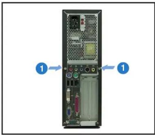
- On the rear panel, locate the two screws that secure the cover to the chassis.

- Use a Phillips (cross) screwdriver to remove the cover screws. Keep the screws for later use.

- Pull the cover slightly toward the rear panel until the cover tabs disengage from the chassis.

- Lift the cover, then set aside.
2.4 Removing the front panel cover
To remove the front cover:
- Lift the front cover hooks outward until they disengage from the chassis.
- Carefully remove the front cover, then set it aside.

2.5 Removing the storage drive assembly
Removing the storage drive assembly provides you more space when installing the CPU and the CPU fan and heatsink assembly.
To remove the front cover and storage drive assembly:
- Locate and remove three storage drive assembly screws. Keep the screws for later use.
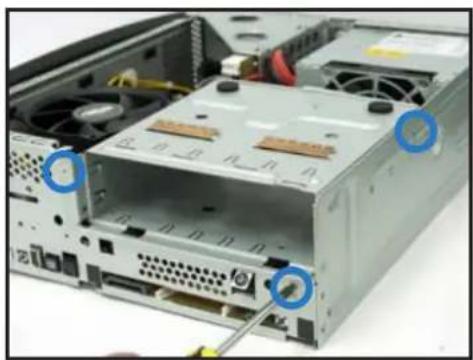

If your system comes with a preinstalled optical drive, disconnect the power, audio, and IDE plugs at the back of the drive before lifting the storage drive assembly.
- Slightly lift the storage drive assembly until its hooks are released from the chassis holes. Set the storage drive assembly aside.


When removing the storage drive assembly, make sure to hold or support it firmly. The assembly may accidentally drop and damage other system components.
2.6 Installing a CPU
The motherboard comes with a surface mount 939-pin Zero Insertion Force (ZIF) socket designed for AMD Athlon® 64 processor.
The 128-bit wide data paths of this processor can run applications faster than processors with only 32-bit or 64-bit wide data paths.

Gold triangle
Take note of the marked corner (with gold triangle)
on the CPU. This mark should match a specific corner on the socket to ensure correct installation.
2.6.1 Removing the CPU fan and heatsink assembly
The system package includes a pre-installed proprietary CPU fan and heatsink assembly to provide an efficient thermal solution to the CPU. You need to remove the CPU fan and heatsink assembly to install the CPU.
To remove the CPU fan and heatsink assembly:
- Disconnect the CPU fan cable.
- Remove two screws securing the blower to the CPU fan. Set the blower aside.

- Unhook and slide out the metal clips that secure the fan and heatsink assembly to the retention module.
Locking lever
- Lift the CPU fan and heatsink assembly, then set aside.

2.6.2 CPU installation
To install the CPU:
- Locate the 939-pin CPU socket on the motherboard.

- Press the CPU socket lever sideways, then lift it up to a 90°-100° angle.

- Match the gold triangle on the CPU with the small triangle on the socket. Insert the CPU into the socket until it fits in place.
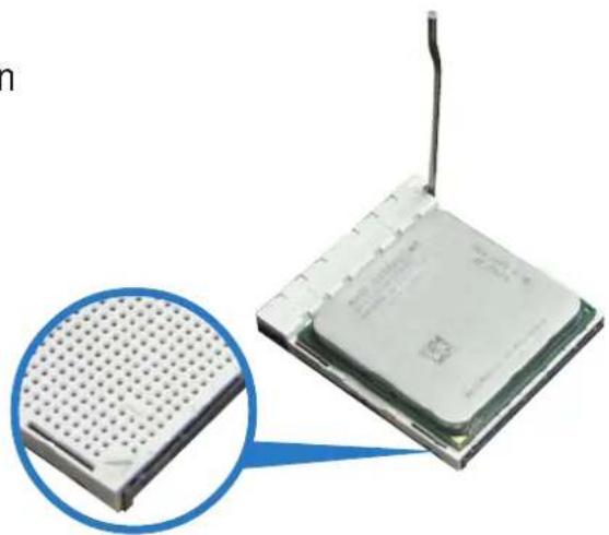
- Push down the socket lever to secure the CPU.


Make sure to install the CPU fan, blower, and heatsink assembly on top of the installed CPU.
2.6.3 Reinstalling the CPU fan and heatsink assembly
To reinstall the CPU fan and heatsink assembly:
- Position the CPU fan and heatsink assembly on top of the installed CPU.
- Connect the CPU cable to the CPU fan connector on the motherboard.
- Align the metal clips to the side rail of the CPU fan and heatsink assembly, with the locking levers in the reverse orientation.
- Snap the hook of each metal clip into the hole of the retention module.
- Carefully press down the locking lever and hook its end into the retention module.
- Position the blower on top of the CPU fan and heatsink assembly as shown.
- Secure the blower to the CPU fan and heatsink assembly with the screws you removed earlier.


Do not forget to connect the CPU fan connector! Hardware monitoring errors can occur if you fail to plug this connector.
2.7 Installing memory modules
2.7.1 Overview
The system motherboard comes with two Double Data Rate (DDR) Dual Inline Memory Modules (DIMM) sockets that support up to 2 GB non-ECC PC5300/4200/3200 DDR DIMMs.
Refer to the illustration below for the location of the DDR DIMM sockets.

184-pin DDR DIMM sockets

For optimum compatibility, we recommend that you obtain memory modules from the same vendor. Refer to section 2.7.3 for a list of qualified DDR vendors.
2.7.2 Memory configurations
You may install 64 MB, 128 MB, 256 MB, 512 MB, and 1 GB DDR DIMMs to the DIMM sockets.

When installing one DDR DIMM module, install into DIMM_A1 slot only.
2.7.3 Qualified Vendors List
The following table lists the memory modules that have been tested and qualified for use with this motherboard.
DDR 400 Qualified Vendors List
| Size Vendor Model CL Brand | SS/DS Component A* B* | DIMM support | |||||
| 256 MB KINGSTON V58C2256804SAT5(ECC) - - SS KVR400X72C3A/256 | |||||||
| 512 MB KINGSTON V58C2256804SAT5(ECC) - - DS KVR400X72C3A/512 | |||||||
| 512 MB KINGSTON Heat-Sink Package - - DS KHX3200A/512 | • | • | |||||
| 1024 MB KINGSTON Heat-Sink Package - - DS KHX3200ULK2/1G | |||||||
| 256 MB KINGSTON D3208DL3T-5A | - | - | SS | KVR400X64C3A/256 | • • | ||
| 256 MB KINGSTON A2S56D30BTP | - - SS KVR400X64C3A/256 | ||||||
| 512 MB KINGSTON V58C2256804SAT5 | - - DS KVR400X64C3A/512 | • | |||||
| 512 MB KINGSTON HY5DU12822BT-D43 | - | - | SS | KVR400X64C3A/512 | • • | ||
| 1024 MB KINGSTON HYB25D512800BE-5B | - - DS KVR400X64C3A/1G | ||||||
| 256 MB SAMSUNG | K4H560838E-TCCC(ECC) | - | SAMSUNG | SS | M381L3223ETM-CCC | ||
| 512 MB SAMSUNG | K4H560838E-TCCC(ECC) | - | SAMSUNG | DS | M381L6423ETM-CCC | ||
| 256 MB SAMSUNG | K4H560838F-TCCC | - | SAMSUNG | SS | M368L3223FTN-CCC | • | |
| 512 MB SAMSUNG | K4H560838F-TCCC | - | SAMSUNG | DS | M368L6423FTN-CCC | • • | |
| 256 MB Infineon | HYB25D256800CE-5C | 3 | Infineon | SS | HYS64D32300HU-5-C | • • | |
| 512 MB Infineon | HYB25D256800CE-5C | - | Infineon | DS | HYS64D64320HU-5-C | • | |
| 256 MB Infineon | HYB25D512160CE-5C | 3 | Infineon | SS | HYS64D32301HU-5-C | • • | |
| 512 MB Infineon | HYB25D512800CE-5C | 3 | Infineon | SS | HYS64D64300HU-5-C | • • | |
| 1024 MB Infineon | HYB25D512800CE-5B | 3 | Infineon | DS | HYS64D128320HU-5-C | ||
| 256 MB CORSAIR | W942508BH-5 | - | - | SS | CMX256A-3200C2PT | • | |
| 512 MB CORSAIR | Heat-Sink Package | - | - | DS | CMX512-3200C2 | • • | |
| 512 MB CORSAIR | VS32M8-5 | - | - | DS | VS512MB400 | • • | |
| 512 MB CORSAIR | Heat-Sink Package - | - DS CMXP512-3200XL | |||||
| 1024 MB CORSAIR | Heat-Sink Package | - | - | DS | TWINX2048-3200C2 | ||
| 256 MB Hynix | HY5DU56822DT-D43 | - | - | SS | HYMD232646D8J-D43 | • | |
| 512 MB Hynix | HY5DU56822DT-D43 | - | - | DS | HYMD264646D8J-D43 | • • | |
| 256 MB Transcend | K4H560838F-TCCC | 3 | SAMSUNG | SS | TS32MLD64V4F3 | • • | |
| 512 MB Transcend | K4H560838F-TCCC | 3 | SAMSUNG | DS | TS64MLD64V4F3 | • | |
| 1024 MB Transcend | K4H510838B-TCCC | 3 | SAMSUNG | DS | TS128MLD64V4J | • | |
| 256 MB A DATA | K4H560838E-TCCC | 3 | SAMSUNG | SS | MDOSS6F3G31Y0K1E0Z | • | |
| 512 MB A DATA | K4H560838F-TCCC | 3 | SAMSUNG | DS | MDOSS6F3H41Y0N1E0Z | • • | |
| 256 MB A DATA | HY5DU56822CT-D43 | 3 | Hynix | SS | MDOHY6F3G31Y0N1E0Z | • • | |
| 512 MB A DATA | HY5DU56822CT-D43 | 3 | Hynix | DS | MDOHY6F3H41Y0N1E0Z | • • | |
| 256 MB A DATA | ADD8608A8A-5B | 2.5 | - | SS | MDOAD5F3G31Y0D1E02 | • • | |
| 512 MB A DATA | ADD8608A8A-5B | 2.5 | - | DS | MDOAD5F3H41Y0D1E02 | ||
| 256 MB KINGMAX KDL388P4LA-50 | - | - SS MPXB62D-38KT3R | |||||
| 512 MB KINGMAX KDL388P4LA-50 | - | - | DS | MPXC22D-38KT3R | • • | ||
| 256 MB crucial | Heat-Sink Package | 2 | Ballistix | SS | BL3264Z402.8TG | ||
| 512 MB crucial | Heat-Sink Package | 2 | Ballistix | DS | BL6464Z402.16TG | ||
| 256 MB TwinMOS | TMD7608F8E50D | 2.5 | TwinMOS | SS | M2G9I08AIATT9F081AADT | • • | |
| 512 MB TwinMOS | TMD7608F8E50D | 2.5 | TwinMOS | DS | M2G9J16AJATT9F081AADT | • • | |
| 256 MB TwinMOS | TMD7608F8E50D | 2.5 | TwinMOS | SS | M2G9I08A8ATT9F081AADT | • • | |
| 512 MB TwinMOS | TMD7608F8E50D | 2.5 | TwinMOS | DS | M2G9J16A8ATT9F081AADT | • • | |
| 256 MB TwinMOS | TMD7608F8E50I | - | TwinMOS | SS | M2G9I08A8ATT9F081CADT | • • | |
| 512 MB TwinMOS | TMD7608F8E50I | - | TwinMOS | DS | M2G9J16A8ATT9F081CADT | • | |
| 256 MB V-DATA | VDD9616A8A-5C | - | - | SS | MDYVD6F4G2880B1E0H | • | |
(continued on the next page)
| Size Vendor Model CL Brand | SS/DS Component A* B* | DIMM support | |||||
| 256 MB Winbond W942508CH-5 3 Winbond SS W9425GCDB-5 • • | |||||||
| 512 MB Winbond W942508CH-5 - Winbond DS | W9451GCDB-5 | ||||||
| 256 MB GEIL | GL3LC32G88TG-35 | - | - | SS | GL5123200DC | ||
| 512 MB GEIL | GL3LC32G88TG-35 | - | - | DS | GL1GB3200DC | ||
| 256 MB GEIL | GL3LC32G88TG-5A | - | - | SS | GLX2563200UP | • • | |
| 256 MB PSC | A2S56D30BTP | 2.5 | PSC | SS | AL5D8B53T-5B1K | • • | |
| 512 MB PSC | A2S56D30BTP | 2.5 | PSC | DS | AL6D8B53T-5B1K | • | |
| 256 MB NANYA | NT5DS32M8CT-5T | - | - | SS | NT256D64S88C0G-5T | • • | |
| 512 MB NANYA | NT5DS32M8CT-5T | - | - | DS | NT512D64S8HC0G-5T | • • | |
| 256 MB NANYA | NT5DS32M16BT-5T | - | - | SS | NT256D64SH4B0G-5T | • • | |
| 512 MB NANYA | NT5DS64M8BT-5T | - | - | SS | NT512D64S88B0G-5T | • • | |
| 1024 MB NANYA | NT5DS64M8BT-5T | - | - | DS | NT1GD64S8HB0G-5T | • | |
| 512 MB NANYA | NT5DS64M8CS-5T | - | - | SS | NT512D64S88C0GY-5T | • • | |
| 1024 MB NANYA | NT5DS64M8CS-5T | - | - | DS | NT1GD64S8HC0GY-5T | • • | |
| 256 MB Novax | C2S56D30TP-5 | 2.5 | CEON | SS | 96M425653CE-40TB6 | • • | |
| 512 MB Novax | C2S56D30TP-5 | 2.5 | CEON | DS | 96M451253CE-40TB6 | • | |
| 256 MB CENTURY | K4H560838E-TCCC | - | - | SS | DXV6S8SSCCE3K27E | ||
| 512 MB CENTURY | K4H560838E-TCCC | - | - | DS | DXV2S8SSCCE3K27E | • | |
| 256 MB CENTURY | DD2508AMTA | - | - | SS | DXV6S8EL5BM3T27C | • • | |
| 512 MB CENTURY | DD2508AMTA | - | - | DS | DXV2S8EL5BM3T27C | • • | |
| 256 MB CENTURY | DD2508AMTA | - | - | SS | DXV6S8EL5B | • • | |
| 256 MB CENTURY | HY5DU56822BT-D43 | - | - | SS | DXV6S8HXD43B | • • | |
| 256 MB CENTURY | HY5DU56822DT-D43 | - | - | SS | DXV6S8HXD43D | • • | |
| 512 MB CENTURY | DD2508AMTA | - | - | DS | DXV2S8EL5B | • | |
| 512 MB CENTURY | HY5DU56822BT-D43 | - | - | DS | DXV2S8HXD43B | • | |
| 512 MB CENTURY | HY5DU56822DT-D43 | - | - | DS | DXV2S8HXD43D | • • | |
| 256 MB CENTURY | DD2508AKTA-5B-E | - | - | SS | DXV6S8EL5B/HP | • • | |
| 512 MB CENTURY | DD2508AKTA-5B-E | - | - | DS | DXV2S8EL5B/HP | • • | |
| 256 MB CENTURY | MT46V32M8TG-5BG | - | - | SS | DXV6S8MC5B | • • | |
| 512 MB CENTURY | MT46V32M8TG-5BG | - | - | DS | DXV2S8MC5B | • | |
| 512 MB CENTURY | HY5DU12822CTP-D43 | - | - | SS | DXV2H8 | • | |
| 1024 MB CENTURY | HY5DU12822CTP-D43 | - | - | DS | DXV0H8 | • • | |
| 256 MB Elixir | N2DS25680CT-5T | - | - | SS | M2U25664DS88C3G-5T | • • | |
| 512 MB Elixir | N2DS25680CT-5T | - | - | DS | M2U51264DS8HC3G-5T | ||
| 512 MB Elixir | N2DS51280BT-5T | - | - | SS | M2U51264DS88B1G-5T | • | |
| 1024 MB Elixir | N2DS51280BT-5T | - | - | DS | M2U1G64DS8HB1G-5T | • | |
| 256 MB Kreton | VT3225804T-5 | - | VT | SS | - | • • | |
| 512 MB Kreton | VT3225804T-5 | - | VT | DS | - | • | |
| 256 MB Veritech | VT56DD32M8PC-5 | 3 | VM | SS | VU256FLTM25C | • • | |
| 512 MB Veritech | VT56DD32M8PC-5 | 3 | VM | DS | VU512FLTM25C | • • | |
| 256 MB Pmi | V58C2256804SAT5B | 2.5 | MOSEL | SS | MD44256VIT3208GMHA01 | • | |
| 512 MB Pmi | V58C2256804SAT5B | 2.5 | MOSEL | DS | MD44512VIT3208GATA03 | • • | |
| 256 MB ProMOS | V58C2256804SCT5B | 2.5 | - | SS | V826632K24SCTG-D0 | • | |
| 512 MB ProMOS | V58C2256804SCT5B | 2.5 | - | DS | V826664K24SCTG-D0 | ||
| 256 MB Deutron | A2S56D30CTP | 2.5 | PSC | SS | AL5D8C53T-5B1T | • • | |
| 512 MB Deutron | A2S56D30CTP | 2.5 | PSC | DS | AL6D8C53T-5B1T | • | |
| 256 MB Aeneon | AED83T500 | 3 | Aeneon | SS | AED560UD00-500C88X | ||
| 256 MB Aeneon | AED83T500 | 3 | Aeneon | SS | AED560UD00-500C88Z | • | |
| 512 MB Aeneon | AED93T500 | 3 | Aeneon | SS | AED660UD00-500B98X | • • | |
(continued on the next page)
DDR 400 Qualified Vendors List
| Size Vendor Model CL Brand | SS/DS Component A* B* | DIMM support | |||||
| 512 MB Aeneon AED83T500 - Aeneon DS AED660UD00-500C88X • | |||||||
| 256 MB | SimpleTech | 838S032T05A | - | - | SS | SVM-DDR3200/256 | |
| 512 MB | SimpleTech | 838S032T05A | - | - | DS | SVM-DDR3200/512 | • • |
| 1024 MB | Patriot | Heat-Sink Package | - | - | DS | PDC1G3200+XBLK | |
| 512 MB | MDT | 25B25680-50520 | - | - | DS | M512-400-16B | |
DDR 333 Qualified Vendors List
| Size Vendor Model CL Brand | SS/DS | Component A* B* | DIMM support | ||||
| 256 MB | KINGSTON | D3208DH1T-6 | - | - | SS | KVR333X64C25/256 | |
| 512 MB | KINGSTON | D3208DH1T-6 | - | - | DS | KVR333X64C25/512 | • |
| 256 MB | SAMSUNG | K4H560838E-TCB3 | - | - | SS | M368L3223ETN-CB3 | • |
| 512 MB | SAMSUNG | K4H560838E-TCB3 | - | - | DS | M368L6423ETN-CB3 | • • |
| 256 MB | SAMSUNG | K4H560838E-TCB3(ECC) | - | - | SS | M381L3223ETM-CB3 | |
| 512 MB | SAMSUNG | K4H560838E-TCB3(ECC) | - | - | DS | M381L6423ETM-CB3 | |
| 256 MB | SAMSUNG | K4H560838F-TCB3 | - | - | SS | M368L3223FTN-CB3 | • |
| 256 MB | CORSAIR | VS32M8-6 | - | - | SS | VS256MB333 | • |
| 512 MB | CORSAIR | VS32M8-6 | - | - | DS | VS512MB333 | • |
| 256 MB | NANYA | NT5DS32M8CT-6K | - | - | SS | NT256D64S88C0G-6K | • • |
| 512 MB | NANYA | NT5DS32M8CT-6K | - | - | DS | NT512D64S8HC0G-6K | • • |
| 256 MB | NANYA | NT5DS32M16BT-6K | - | - | SS | NT256D64SH4B0G-6K | |
| 512 MB | NANYA | NT5DS64M8BT-6K | - | - | SS | NT512D64S88B0G-6K | • • |
| 1024 MB | NANYA | NT5DS64M8BT-6K | - | - | DS | NT1GD64S8HB0G-6K | • |
| 512 MB | NANYA | NT5DS64M8CS-6K | - | - | SS | NT512D64S88C0GY-6K | • • |
| 1024 MB | NANYA | NT5DS64M8CS-6K | - | - | DS | NT1GD64S8HC0GY-6K | • • |
| 512 MB | MOSEL | V58C2256804SAT6 | - | - | DS | MPMC225-383 | • • |
| 256 MB | Aeneon | AED83T600 | - | - | SS | AED560UD00-600C88X | • |
A* : Supports one module inserted as Single-channel memory configuration.
B*: Supports one pair of modules inserted into both slots as one pair of Dual-channel memory configuration.

Obtain DDR DIMMs only from ASUS qualified vendors. Visit the ASUS website (www.asus.com) for the latest QVL.
2.7.4 Installing a DIMM

- Make sure to unplug the power supply before adding or removing DIMMs or other system components. Failure to do so may cause severe damage to both the motherboard and the components.
- Reinstall the CPU fan and heatsink assembly before installing the DIMM(s) to avoid damaging the retaining clips of the DIMM sockets. Refer to the previous section for details on how to reinstall the CPU fan and heatsink assembly.
To install a DIMM:
- Locate the DIMM sockets in the motherboard.
- Unlock a DIMM socket by pressing the retaining clips outward.
- Align a DIMM on the socket such that the notch on the DIMM matches the break on the socket.

- Firmly insert the DIMM into the socket until the retaining clips snap back in place and the DIMM is properly seated.
2.7.5 Removing a DIMM
To remove a DIMM:
- Simultaneously press the retaining clips outward to unlock the DIMM.

Support the DIMM lightly with your fingers when pressing the retaining clips. The DIMM might get damaged when it flips out with extra force.
- Remove the DIMM from the socket.


Remove the CPU fan and heatsink assembly before removing the memory module(s). Incorrect removal sequence may damage the DIMM socket retaining clips.
2.8 Installing PCI cards
In the future, you may need to install PCI cards to the system. The system motherboard has one PCI slot with a preinstalled PCI riser assembly that supports two PCI cards.

Make sure to unplug the power cord before adding or removing expansion cards. Failure to do so may cause you physical injury and damage motherboard components.
2.8.1 PCI slots
The PCI slots support PCI cards such as a LAN card, SCSI card, USB card, and other cards that comply with PCI specifications. The following figure shows a LAN card installed on a PCI slot.

2.8.2 PCI card installation
To install a PCI card:
- Slightly lift the PCI riser assembly until it disengages from the chassis.

- Place the PCI riser assembly on a flat surface.
- Remove the bracket opposite the PCI slot you wish to use. Keep the screw for later use.

- Align the PCI card connector with the slot and press firmly until the card is completely seated on the slot. Secure the PCI card to the PCI riser assembly with the screw you removed earlier.

- Reinstall the PCI riser assembly to the system chassis.

2.8.3 Configuring an expansion card
After installing the expansion card, configure the card by adjusting the software settings.
- Turn on the system and change the necessary BIOS settings, if any. See Chapter 5 for information on BIOS setup.
- Assign an IRQ to the card. Refer to the tables below.
- Install the software drivers for the expansion card.
Standard interrupt assignments
| IRQ Priority Standard Function |
| 0 1 System Timer |
| 1 2 Keyboard Controller |
| 2 - Redirect to IRQ#9 |
| 3 11 IRQ Holder for PCI Steering* |
| 4 12 Communications Port (COM1)* |
| 5 13 IRQ Holder for PCI Steering* |
| 6 14 Floppy Disk Controller |
| 7 15 Printer Port (LPT1)* |
| 8 3 System CMOS/Real Time Clock |
| 9 4 IRQ Holder for PCI Steering* |
| 10 5 IRQ Holder for PCI Steering* |
| 11 6 IRQ Holder for PCI Steering* |
| 12 7 PS/2 Compatible Mouse Port* |
| 13 8 Numeric Data Processor |
| 14 9 Primary IDE Channel |
| 15 10 Secondary IDE Channel |
* These IRQs are usually available for ISA or PCI devices.
IRQ assignments for the system motherboard
| A | B | C | D | |
| PCI slot 1 used — | — | — | ||
| PCI slot 2 | — used — | — | ||
| IEEE 1394 | — | — | — used | |

When using a PCI card on shared slots, ensure that the drivers support "Share IRQ" or that the cards do not need IRQ assignments; otherwise, conflicts will arise between the two PCI groups, making the system unstable and the card inoperable.
2.9 Installing optical and storage drives
2.9.1 Optical and storage drives installation
The system supports one Ultra ATA 100/66 IDE or one Serial ATA hard disk drive.

Configure your hard disk drive as Master device before installing it in the storage drive assembly. Refer to the HDD documentation on how to set the drive as a Master device.
To install an IDE hard disk drive and optical drive:
- Turn the storage drive assembly upside down with the 3.5-inch bay on top of the 5.25-inch bay.
- Insert the optical drive upside down to the 5.25-inch bay, then secure it with two screws on both sides.
- Turn the storage drive assembly, insert the hard disk drive upside down to the 3.5-inch bay, then secure it with two screws on both sides.


- Connect the black plug of the IDE cable to the optical drive, then the gray plug to the hard disk drive.
- Connect the 4-pin power plugs to the power connectors at the back of the drives.
- Install the storage drive assembly to the chassis.
- Secure the storage drive assembly with three screws.


To install a Serial ATA hard disk drive:
- Follow steps 1-3 of the previous section.
- Connect one end of the supplied
7-pin SATA cable to the connector at the back of the drive, then connect the other end to the SATA connector on the motherboard. See page 4-7 for the location of the Serial ATA connector.

- For Serial ATA HDDs with a 4-pin power connector:
Connect a 4-pin (female) power plug from the power supply unit (PSU) to the 4-pin (male) power connector at the back of the drive.
For Serial ATA HDDs without a 4-pin power connector:
Use the supplied SATA power cable. Connect a 4-pin plug (female) from the PSU to the 4-pin (male) plug of the SATA power cable. Connect the 15-pin SATA power plug to the power connector at the back of the drive.

2.9.2 Recommended optical drive dimension
You must consider the following optical drive requirements when installing a new optical drive or replacing a defective one.

We recommend that you install and use an ASUS optical drive on this system.
Optical drive buttons
The stop/eject button area of the DVD/CD-ROM drive should be less than or equal to 21.9 millimeters from the right edge of the drive.

Optical drive tray
The optical drive tray door should not exceed 4.5 millimeters from the bottom edge of the drive tray. The height of the bottom edge of the drive tray should be less than or equal to 13 millimeters in parallel with the lower drive screw holes.

Optical drive cover thickness and length
The thickness of the optical drive front panel cover should be less than or equal to 7 millimeters and the length of the drive should be less than or equal to 208 millimeters.

2.10 Replacing the cover
After installing all system components and reconnecting all cables, replace the system cover by following these instructions.

- Replace the front panel cover by fastening its hooks to the chassis holes until they fit in place.

- Position the cover at least two inches from the front panel, then align the cover hooks to the chassis rail.

- Push the system cover toward the front panel until it fits in place.

- Secure the system cover with the screws you removed earlier.
2.11 Removing and reinstalling the foot stand
The system comes with a removable foot stand for vertical desktop placement. Follow the instructions to remove or reinstall the foot stand.
2.11.1 Installing the foot stand
To install the foot stand:
- Locate six tab holes on the bottom of the chassis.
- Match the foot stand hooks to the holes on the chassis.

- Pull the foot stand in the direction of the arrow until the lock clicks into place.

2.11.2 Removing the foot stand
To remove the foot stand:
- Lay the system upside down on a flat and stable surface.
- Locate the foot stand lock.
- Use your thumb to push the lock toward the rear panel until the foot stand tabs are released from the chassis holes.
- Lift the foot stand, then set it aside.


2.12 Power supply unit information
The system comes with a 250 W power supply unit (PSU).
2.12.1 Voltage selector
The PSU has a 115 V/230 V voltage selector switch located beside the power socket. Use this switch to select the appropriate voltage according to the voltage supply in your area.

The voltage selector is set to 230 V by default.
If the voltage supply in your area is 100-127 V, set the switch to 115 V.
If the voltage supply in your area is 200-240 V, set the switch to 230 V.


Setting the switch to 115 V in a 230 V environment will seriously damage the system!
2.12.2 Power supply specifications
Input Characteristics
| Input Voltage Range Min Nom Max |
| Range 1 90V 100-127V 132VRange 2 180V 200-240V 264V |
| Input Frequency Range 47 Hz to 63 Hz |
| Maximum Input ac Current 7A max. at 115Vac4A max. at 230Vac, full load |
| Efficiency 65% min. at input 115Vac/230Vac and output full load |
| Current harmonic Meet IEC61000-3-2 Class D (input power from 75W to max. continue power.) |
| AC Inrush Current Peak inrush current shall be limited to 100A warm start. |
Output Characteristics
| Output Voltage | Load Range | Regulation | Ripple Max | ||
| Min | Max | Min | Max | ||
| +5V | 0.5A | 16A | -5% | +5% | 50mVp-p |
| +12V | 1A | 16A | -5% | +5% | 120mVp-p |
| -12V | 0A | 0.8A | -10% | +10% | 120mVp-p |
| +3.3V | 0.3A | 16A | -5% | +5% | 50mVp-p |
| +5VSB | 0A | 2A | -5% | +5% | 50mVp-p |
Over-Voltage Protection (OVP)
| Output Voltage | Maximum Voltage |
| +5V | 6.5V |
| +3.3V | 4.6V |
| +12V | 15.5V |
| +5VSB | 7V |

The power supply will shut down and latch off for shorting +5V, +12V, -12V, or +3.3V. By shorting +5VSB, the power supply can latch down or automatically recover when the fault condition is removed
2.13 Connecting devices
To the rear panel
To the front panel
Chapter 3
This chapter helps you to power up and use the system for the first time. This part also provides information on how to install drivers and utilities from the support CD.

Starting up
3.1 Installing an operating system
The ASUS book size barebone system supports Windows® 2000 / XP operating systems (OS). Always install the latest OS version and corresponding updates so you can maximize the features of your book size barebone system.

Because motherboard settings and hardware options vary, use the setup procedures presented in this chapter for general reference only. Refer to your OS documentation for detailed information.
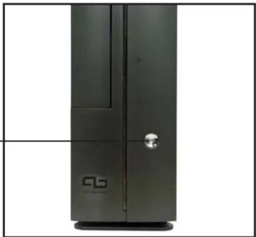
3.2 Powering up
The system power button is located on the front panel. Press the system power button (⏻) to enter the OS.
System power button
3.3 Using the system
The following sections illustrate how to use the storage card reader slots, and the optical drive.
3.3.1 CompactFlash card slot
The system comes with a CompactFlash card slot that supports CompactFlash cards and Microdrive.
CompactFlash card slot

3.3.2 Storage card slot
A 3-in-1 storage card reader comes pre-installed in your ASUS book size barebone system. The storage card reader supports the following storage cards:
- Memory Stick® / Pro™
- Secure Digital™
- MultimediaCard
3-in-1 card reader

3.3.3 Optical drive
If your system comes with an installed optical drive, follow these instructions to insert a CD/DVD into the drive.
- Press the EJECT button of the optical drive.
- Place a CD/DVD on the drive tray. Make sure the CD/DVD is properly seated on the tray locks.
- Push the drive tray back into the drive.

Tray locks
3.4 Support CD information
The support CD that came with the system contains useful software and several utility drivers that enhance the system features.

- Screen display and driver options may not be the same for other operating system versions.
- The contents of the support CD are subject to change at any time without notice. Visit the ASUS website for updates.
3.4.1 Running the support CD
To begin using the support CD, place the CD in your optical drive. The CD automatically displays the Drivers menu if Autorun is enabled in your computer.


If Autorun is NOT enabled in your computer, browse the contents of the support CD to locate the file ASSETUP.EXE from the BIN folder. Double-click the ASSETUP.EXE to run the CD.
3.4.2 Drivers menu
The drivers menu shows the available device drivers if the system detects installed devices. Install the necessary drivers to activate the devices.
AMD Cool 'n' Quiet Driver
Click this item to install the AMD Cool 'n' Quiet™ Driver.
NVIDIA nForce Chipset Driver
Click this item to install the NVIDIA® nForce™ Driver.
NVIDIA GeForce 61X0 GPU Driver
Click this item to install the NVIDIA® GeForce™ 61X0 GPU Driver.
Realtek Audio Driver
Click this item to install the Realtek Audio Driver.
USB 2.0 Driver
Click this item to install the USB 2.0 Driver.
3.4.3 Utilities
The Utilities tab displays the applications and software that the motherboard supports.

ASUS PC Probe II
This utility continuously monitors vital system information such as fan rotations, CPU temperature, and system voltages, and alerts you on any detected problems. This utility helps you keep your computer in a healthy operating condition.
ASUS Update
This item installs the ASUS Update that allows you to update the motherboard BIOS and drivers. This utility requires an Internet connection either through a network or an Internet Service Provider (ISP).
ASUS Screensaver
This item installs the ASUS Screensaver.
ADOBE Acrobat Reader V7.0
This item installs the Adobe® Acrobat Reader®. The Acrobat® Acrobat Reader® software is for viewing files saved in Portable Document Format (PDF).
ASUS Cool 'n' Quiet Utility
Installs the ASUS Cool 'n' Quiet™ utility.
Microsoft DirectX 9.0c
Installs the Microsoft® DirectX 9.0c driver.
USB2.0 Card Reader Software
This item installs the USB2.0 Card Reader Software.
Anti-Virus Utility
The anti-virus application scans, identifies, and removes computer viruses. View the online help for detailed information.
3.4.4 ASUS contact information
Click the Contact tab to display the ASUS contact information.

3.4.5 Other information
The icons on the top right side of the screen give additional information on the motherboard and the contents of the support CD. Click an icon to display the specified information.
Motherboard info Motherboard info
Displays the general specifications of the motherboard.
![ASUS A8NBL motherboard support CD - Windows XP Home/Professional Drivers Utilities Contact [Mainboard] Product : A8NBL Manufacturer : ASUSTek Computer INC. Version : 1.xx [BIOS] Version : ASUS A8NBL ACPI BIOS Revision 0103 11.07/2005 Vendor : Phoenix Technologies, LTD Released Date : 11/07/2005 ROM…](/content/2026/06/1350456/images/f191c7be3c5dd160ee8bb76477d121be63c0abc794946ae1287fa6286fb016b7.jpg)
Browse this CDBrowse this CD
Displays the support CD contents in graphical format.

Technical support form Technical support form
Displays the ASUS Technical Support Request Form that you have to fill out when requesting technical support.

FilelistFilelist
Displays the contents of the support CD and a brief description of each in text format.

Chapter 4
This chapter gives information about the motherboard that comes with the system. This chapter includes the motherboard layout, jumper settings, and connector locations.

Motherboard information
4.1 Introduction
The ASUS motherboard comes already installed in the ASUS book size barebone system. This chapter provides technical information about the motherboard for future upgrades or system reconfiguration.
4.2 Motherboard layout
![graph TD A["CPU_FAN1"] --> B["ATX12V"] C["DDR DIMMBA1 (64 bit, 184-pin module)"] --> D["DDR DIMMB1 (64 bit, 184-pin module)"] E["DDR DIMMBA1 (64 bit, 184-pin module)"] --> F["DDR DIMMBA1 (64 bit, 184-pin module)"] G["DDR DIMMBA1 (64 bit, 184-pin module)"] --> H["DDR DIMMBA1 (64 bit, 184-pin module)"…](/content/2026/06/1350456/images/18561e687792eee618f58b176136d37011227bf2952a08f639b7ef6be2ee03dc.jpg)
4.3 Jumper
1. Clear RTC RAM (CLRTC)
This jumper allows you to clear the Real Time Clock (RTC) RAM in CMOS. You can clear the CMOS memory of date, time, and system setup parameters by erasing the CMOS RTC RAM data. The RAM data in CMOS, that include system setup information such as system passwords, is powered by the onboard button cell battery.
To erase the RTC RAM:
- Turn OFF the computer and unplug the power cord.
- Remove the battery.
- Move the jumper cap from pins 1-2 (default) to pins 2-3. Keep the cap on pins 2-3 for about 5-10 seconds, then move the cap back to pins 1-2.
- Reinstall the battery.
- Plug the power cord and turn ON the computer.
- Hold down the key during the boot process and enter BIOS setup to re-enter data.


Except when clearing the RTC RAM, never remove the cap on CLRTC jumper default position. Removing the cap will cause system boot failure.
4.4 Internal connectors
This section describes and illustrates the connectors on the motherboard. See section "1.4 Rear panel" for the description of the rear panel connectors.
1. USB connector (10-1 pin USB34)
If the rear panel USB 2.0 ports are inadequate, a USB header is available at midboard to accommodate two additional USB ports. You may connect the cable of a two-port USB module to this connector, then mount the module to an open slot in the chassis.

2. Rear panel TV and audio ports connector (14-1 pin TVOUT_R)
This interface is connected to the ASUS proprietary daughtercard that supports the rear panel audio I/O, S-Video, and composite video ports.

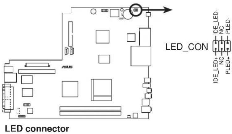
3. LED connector (6-pin LED_CON)
This connector supports the Power and HDD activity LEDs in the system front panel.
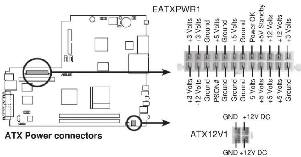
4. ATX power connectors (24-pin EATXPWR, 4-pin ATX12V)
These connectors are for the 24-pin and 4-pin power plugs from the power supply unit. The plugs from the power supply unit are designed to fit these connectors in only one orientation. Find the proper orientation and push down firmly until the connectors completely fit.
5. IDE connector (40-1 pin PRI_IDE)
This connector is for an Ultra DMA 133/100/66 signal cable. The Ultra DMA 133/100/66 signal cable has three connectors: a blue connector for the primary IDE connector on the motherboard, a black connector for an Ultra DMA 133/100/66 IDE slave device (optical drive/hard disk drive), and a gray connector for an Ultra DMA 133/100/66 IDE master device (hard disk drive). If you install two hard disk drives, you must configure the second drive as a slave device by setting its jumper accordingly. Refer to the hard disk documentation for the jumper settings.

Pin 20 on the IDE connector is removed to match the covered hole on the Ultra DMA cable connector. This prevents incorrect insertion when you connect the IDE cable.

6. Serial ATA connector (7-pin SATA1)
This next generation connector supports the thin Serial ATA cable for a Serial ATA hard disk drive. The current Serial ATA interface allows up to 150 MB/s data transfer rate, faster than the standard parallel ATA with 133 MB/s (UltraATA133).

Important notes on Serial ATA

- The Serial ATA cable is smaller and more flexible, allowing easier routing inside the chassis. The lower pin count of the Serial ATA cable eliminates the problem caused by the wide, flat ribbon cables of the Parallel ATA interface.
- This motherboard does not support hot plug function for Serial ATA drive and connections. • Install Windows XP TM Service Pack 1 when using Serial ATA.
7. Serial port connector (10-1 pin COM1)
This connector supports the rear panel serial port.

8. Internal audio connectors (4-pin CD)
These connectors allow you to receive stereo audio input from sound sources such as a optical drive, TV tuner, or MPEG card.

9. CPU fan connector (3-pin CPU_FAN)
The fan connectors support the proprietary CPU fan. Connect the fan cable to the connector, matching the black wire to the ground pin.


Do not forget to connect the fan cables to the fan connectors. Lack of sufficient air flow within the system may damage the motherboard components. These are not jumpers! DO NOT place jumper caps on the fan connectors!
Chapter 5
This chapter tells how to change system settings through the BIOS Setup menus and describes the BIOS parameters.
BIOS setup
5.1 Managing and updating your BIOS
The following utilities allow you to manage and update the motherboard Basic Input/Output System (BIOS) setup.
- ASUS EZ Flash (Updates the BIOS using a flash disk during POST.)
- CrashFree BIOS 2 (Updates the BIOS using the support CD when the BIOS gets corrupted.)
- ASUS Update (Updates the BIOS in Windows environment.) Refer to the corresponding section for each utility.
Important notes

- We recommend that you save a copy of the original motherboard BIOS file to a USB flash disk in case you need to restore the BIOS in the future. Copy the original motherboard BIOS using the ASUS Update utility.
- A working BIOS file for this motherboard is in the support CD. Use this file only when you do not have a copy of the original motherboard BIOS file in a USB flash disk or USB floppy disk.
- Visit the ASUS website and download the latest BIOS file for this motherboard using the ASUS Update utility.
5.1.1 ASUS EZ Flash utility
The ASUS EZ Flash feature allows you to update the BIOS without having to go through the long process of booting from a flash disk and using a DOS-based utility. The EZ Flash utility is built into the BIOS chip, so it is accessible by pressing <Alt+F2> during the Power-On Self Tests (POST).
To update the BIOS using EZ Flash:
- Visit the ASUS website (www.asus.com) to download the latest BIOS file for the motherboard and rename it to A8N8L.BIN.
- Save the BIOS file to a flash disk or floppy disk, then restart the system.
- Press <Alt+F2> during POST to display the following.
EZFlash starting BIOS update
Checking for USB floppy...
- Insert the flash disk that contains the BIOS file into a USB port. (If using a floppy disk, make sure it is inside the USB floppy drive and the USB cable is connected to a USB port). When the correct BIOS file is found, EZ Flash performs the BIOS update process and automatically reboots the system when done.
EZFlash starting BIOS update
Checking for USB floppy...
USB floppy found!
Reading file "A8N8L.BIN". Completed.
Start erasing......|
Start programming...|
Flashed successfully. Rebooting.

- Do not shut down or reset the system while updating the BIOS to prevent system boot failure!
- A “USB floppy not found!” error message appears if there is no floppy disk in the drive. An “A8N8L.BIN not found!” error message appears if the correct BIOS file is not found in the USB floppy disk. Make sure that you rename the BIOS file to A8N8L.BIN.
5.1.2 Recovering the BIOS with CrashFree BIOS 2
The CrashFree BIOS 2 auto recovery tool allows you to restore BIOS from the motherboard support CD, or from a USB floppy disk or flash disk that contains the BIOS file, in case the current BIOS on the motherboard fails or gets corrupted.

- Prepare the support CD that came with the motherboard that contains the motherboard BIOS (A8N8L.BIN) before proceeding with the BIOS update process.
- If you have saved a copy of the original motherboard BIOS to a bootable USB floppy disk or USB flash disk, you may also use this disk to restore the BIOS.
To recover the BIOS from the support CD:

Make sure the optical drive is set as secondary master device when recovering the BIOS using the support CD.
- Boot the system.
- When a corrupted BIOS is detected, the following screen message appears.
Bad BIOS checksum. Starting BIOS recovery... Checking for floppy...

The system automatically checks the optical drive.
- Place the support CD in the optical drive. The support CD contains the original BIOS for this motherboard.
Bad BIOS checksum. Starting BIOS recovery... Checking for floppy... Floppy not found! Checking for CD-ROM... CD-ROM found. Reading file "A8N8L.BIN". Completed. Start flashing...

DO NOT shut down or reset the system while updating the BIOS! Doing so may cause system boot failure!
- When the BIOS update process is complete, reboot the system.

The recovered BIOS may not be the latest BIOS version for this motherboard. Visit the ASUS website (www.asus.com) to download the latest BIOS file.
5.1.3 ASUS Update
The ASUS Update is a utility that allows you to update the motherboard BIOS in Windows® environment. This utility is available in the support CD that comes with the motherboard package. ASUS Update requires an Internet connection either through a network or an Internet Service Provider (ISP).
To install ASUS Update:
- Place the support CD in the optical drive. The Drivers menu appears.
- Click the Utilities tab, then click Install ASUS Update VX.XX.XX. See page 3-5 for the Utilities screen menu.
- The ASUS Update utility is copied into your system.
To update the BIOS using the ASUS Update:
- Launch the utility from the Windows desktop by clicking Start > Programs > ASUS > ASUSUpdate > ASUSUpdate. The ASUS Update initial screen appears.
- Select your desired update method, then click Next.

- If you selected updating/downloading from the Internet, select the ASUS FTP site nearest you to avoid network traffic, or choose Auto Select. Click Next.

- From the FTP site, select the BIOS version that you wish to download. Click Next.
- Follow the instructions on the succeeding screens to complete the update process.

If you selected the option to update the BIOS from a file, a window pops up prompting you to locate the file. Select the file, click Save, then follow the screen instructions to complete the update process.

5.2 BIOS Setup program
This motherboard supports a programmable Firmware Hub (FWH) that you can update using the provided utility described in section 5.1 Managing and updating your BIOS.
Use the BIOS Setup program when you are installing a motherboard, reconfiguring your system, or prompted to "Run Setup." This section explains how to configure your system using this utility.
Even if you are not prompted to use the Setup program, you may want to change the configuration of your computer in the future. For example, you may want to enable the security password feature or make changes to the power management settings. This requires you to reconfigure your system using the BIOS Setup program so that the computer can recognize these changes and record them in the CMOS RAM of the firmware hub.
The firmware hub stores the Setup utility. When you start up the computer, the system provides you with the opportunity to run this program. Press during the Power-On Self Test (POST) to enter the Setup utility, otherwise, POST continues with its test routines.
If you wish to enter Setup after POST, restart the system by pressing + + , or by pressing the reset button on the system chassis. You can also restart by turning the system off and then back on. Do this last option only if the first two failed.
The Setup program is designed to make it as easy to use as possible. It is a menu-driven program, which means you can scroll through the various sub-menus and make your selections among the predetermined choices.

Because the BIOS software is constantly being updated, the following BIOS setup screens and descriptions are for reference purposes only, and may not exactly match what you see on your screen.
5.2.1 BIOS menu bar
The top of the screen has a menu bar with the following selections:
MAIN: Use this menu to make changes to the basic system configuration.
ADVANCED: Use this menu to enable and make changes to the advanced features.
POWER: Use this menu to configure and enable Power Management features.
BOOT: Use this menu to configure the default system device used to locate and load the Operating System.
EXIT: Use this menu to exit the current menu or to exit the Setup program.
To access the menu bar items, press the right or left arrow key on the keyboard until the desired item is highlighted.
5.2.2 Legend bar
At the bottom of the Setup screen is a legend bar. The keys in the legend bar allow you to navigate through the various setup menus. The following table lists the keys found in the legend bar with their corresponding functions.
| or | Displays the A general Help screen from anywhere in the BIOS Setup |
| Jumps to the Exit menu or returns to the main menu from a sub-menu | |
| Left or Right arrow | Selects the menu item to the left or right |
| Up or Down arrow | Moves the highlight up or down between fields |
| - (minus key) | Scrolls backward through the values for the highlighted field |
| + (plus key) or spacebar | Scrolls forward through the values for the highlighted field |
| Brings up a selection menu for the highlighted field | |
| or | Moves the cursor to the first field |
| or | Moves the cursor to the last field |
| Resets the current screen to its Setup Defaults | |
| Saves changes and exits Setup |
General help
In addition to the Item Specific Help window, the BIOS setup program also provides a General Help screen. You may launch this screen from any menu by simply pressing . The General Help screen lists the legend keys and their corresponding functions.
Saving changes and exiting the Setup program
See "5.7 Exit Menu" for detailed information on saving changes and exiting the setup program.
Scroll bar
When a scroll bar appears to the right of a help window, it indicates that there is more information to be displayed that will not fit in the window. Use and or the up and down arrow keys to scroll through the entire help document. Press to display the first page, press to go to the last page. To exit the help window, press or .
Sub-menu

Note that a right pointer symbol (as shown on the left) appears to the left of certain fields. This pointer indicates that you can display a sub-menu from this field. A sub-menu contains additional options for a field parameter. To display a sub-menu, move the highlight to the field and press . The sub-menu appears. Use the legend keys to enter values and move from field to field within a sub-menu as you would within a menu. Use the key to return to the main menu.
Take some time to familiarize yourself with the legend keys and their corresponding functions. Practice navigating through the various menus and sub-menus. If you accidentally make unwanted changes to any of the fields, use the set default hot key to load the Setup default values. While moving around through the Setup program, note that explanations appear in the Item Specific Help window located to the right of each menu. This window displays the help text for the currently highlighted field.
5.3 Main Menu
When you enter the Setup program, the following screen appears.
| Phoenix - Award BIOS CMOS Setup Utility | |
| Main Advanced Power Boot Exit | |
| System Time 09:40:12 System Date Fri, Dec 23 2005 ► Primary IDE Master [HDS7288080PLAT20] ► Primary IDE Slave [ASUS CD-S360] ► First SATA Master [None] ► Second SATA Master [None] HDD SMART Monitoring [Disabled] Installed Memory 512 MB Usable Memory 479 MB | Select Menu |
| Item Specific Help▶ Change the internal clock. | |
| F1:Help ↑↓:Select Item -/+ : Change Value F5:Setup Defaults ESC:Exit ←→:Select Menu Enter: Select SubMenu F10:Save and Exit | |
5.3.1 System Time [xx:xx:xx]
Sets the system to the time that you specify (usually the current time). The format is hour, minute, second. Valid values for hour, minute and second are Hour: (00 to 23), Minute: (00 to 59), Second: (00 to 59). Use the key to move between the hour, minute, and second fields.
5.3.2 System Date [xx/xx/xxxx]
Sets the system to the date that you specify (usually the current date). The format is month, day, year. Valid values for month, day, and year are Month: (1 to 12), Day: (1 to 31), Year: (up to 2084). Use the key to move between the month, day, and year fields.
5.3.3 Primary IDE Master/Slave; First/Second SATA Master
| Phoenix - Award BIOS CMOS Setup Utility | |
| IDE Primary Master | Select Menu |
| Primary IDE Master [Auto] Access Mode [Auto] | Item Specific Help Press [Enter] to select. |
| Capacity XX MB | |
| Cylinder XXXXX | |
| Head XX | |
| Sector XXX | |
| PIO Mode [Auto] | |
| UDMA Mode [Auto] | |
| Transfer Mode UDMA5 | |
| F1:Help ↑↓:Select Item -/+ : Change Value F5:Setup Defaults ESC:Exit ++:Select Menu Enter: Select SubMenu F10:Save and Exit | |
Primary IDE Master [Auto]
Select [Auto] to automatically detect an IDE hard disk drive. If automatic detection is successful, Setup automatically fills in the correct values for the remaining fields on this sub-menu. If automatic detection fails, this may be because the hard disk drive is too old or too new. If the hard disk was already formatted on an older system, Setup may detect incorrect parameters. In these cases, select [Manual] to manually enter the IDE hard disk drive parameters. Refer to the next section for details.
Configuration options: [None] [Auto] [Manual]
![ASUS P1-AH1 - Primary IDE Master [Auto] - 1](/content/2026/06/1350456/images/711da429c09b624c4eec6f5e739b7edd36986b15bdb4b42f64bab21e6d5afa6e.jpg)
Before attempting to configure a hard disk drive, make sure you have the correct configuration information supplied by the drive manufacturer. Incorrect settings may cause the system to fail to recognize the installed hard disk.
Access Mode [Auto]
This item allows the user to select the sector addressing mode. Configuration options: [CHS] [LBA] [Large] [Auto]
PIO Mode [Auto]
This option lets you set a PIO (Programmed Input/Output) mode for the IDE device. Modes 0 through 4 provide successive increase in performance. Configuration options: [Auto] [Mode 0] [Mode 1] [Mode 2] [Mode 3] [Mode 4]
UDMA Mode [Auto]
Ultra DMA capability allows improved transfer speeds and data integrity for compatible IDE devices. Set to [Disabled] to suppress Ultra DMA capability. Configuration options: [Disable] [Auto]
5.3.4 HDD SMART Monitoring [Disabled]
This option allows you to enable or disable the HDD SMART Monitoring function. Configuration options: [Disabled] [Enabled]
5.3.5 Installed Memory [xxx MB]
This field automatically displays the amount of conventional memory detected by the system during the boot process. This item is not user-configurable.
5.3.6 Usable Memory [xxx MB]
This field automatically displays the Usable Memory detected by the system during the boot process. This item is not user-configurable.
5.4 Advanced Menu
The Advanced menu items allow you to change the settings for the CPU and other system devices.

Take caution when changing the settings of the Advanced menu items. Incorrect field values may cause the system to malfunction.
![Phoenix - Award BIOS CMOS Setup Utility Main Advanced Power Boot Exit ► CPU Configuration ► Chipset ► PCIPnP ► Onboard Device Configuration Select Menu Item Specific Help► Press [Enter] to Set. F1:Help ↑↓:Select Item -/+: Change Value F5:Setup Defaults ESC:Exit ++:Select Menu Enter: Select SubMenu F…](/content/2026/06/1350456/images/bd1d6fb5acfaacb1441141d4422c88d859e601f8a5b622edefebf6e41237c614.jpg)
5.4.1 CPU configuration
The items in this menu show the CPU-related information auto-detected by the BIOS.
| Phoenix - Award BIOS CMOS Setup Utility Advanced | |
| CPU Configuration | Select Menu |
| CPU Type AMD Athlon (tm) 64 Processor 3200+ CPU Speed 2010MHz Cache RAM 512K ▶DRAM Configuration AMD K8 Cool 'n' Quiet Control [Enabled] | Item Specific Help▶ DRAM timing and control. |
| F1:Help ↑↓:Select Item -/+ : Change Value F5:Setup Defaults ESC:Exit ++:Select Menu Enter: Select SubMenu F10:Save and Exit | |
DRAM Configuration
| Phoenix - Award BIOS CMOS Setup Utility | |
| Advanced | |
| DRAM Configuration | Select Menu |
| Timing Mode [Auto]× Memclock index value (Mhz) 166Mhz× CAS# latency (Tcl) 2.5× Min RAS# active time (Tras) 7T× RAS# to CAS# delay (Trcd) 3T× Row precharge Time (Trp) 3T× 1T/2T Memory Timing 2TS/W DRAM Over 4G Remapping [Enabled] | Item Specific Help▶▶▶▶▶▶▶▶▶▶▶▶▶▶▶▶▶▶▶▶▶▶▶▶▶▶▶▶▶▶▶▶▶▶▶▶▶▶▶▶▶▶▶▶▶▶▶▶▶▶▶▶▶▶▶▶▶▶▶▶▶▶▶▶▶▶▶▶▶▶▶▶▶▶▶▶▶▶▶▶▶▶▶▶▶▶▶▶▶▶▶▶▶▶▶▶▶▶▶▶> to select DRAM configuration. By [Auto] is recommended. [Manual] allows you to set each configuration on your own. |
| F1:Help ↑↓:Select Item -/+ : Change Value F5:Setup DefaultsESC:Exit ++:Select Menu Enter: Select SubMenu F10:Save and Exit | |
Timing Mode [Auto]
Allows selection of DRAM configuration.
Configuration options: [Auto] [Manual]

The following items become user-configurable when you set the Timing Mode item to [Manual].
Memclock index value (Mhz) [166Mhz]
Allows you to set the DRAM frequency.
Configuration options: [100Mhz] [133Mhz] [166Mhz] [200Mhz]
CAS# latency (Tcl) [2.5]
Allows you to set the latency between the DRAM command and the time the data actually become available. Configuration options: [2] [2.5] [3]
Min RAS# active time (Tras) [7T]
Controls the number of DRAM clocks used for DRAM parameters.
Configuration options: [5T] ~ [15T]
RAS# to CAS# delay (Trcd) [3T]
Controls the latency between the DRAM active command and the R/W command. Configuration options: [2T] ~ [7T]
Row precharge Time (Trp) [3T]
Controls the idle clocks after issuing a precharge command to the DRAM.
Configuration options: [2T] ~ [7T]
1T/2T Memory Timing [2T]
Allows the DRAM commands and address to be driven for either one or two clock cycles. Configuration options: [1T] [2T]
S/W DRAM Over 4G Remapping [Enabled]
Enables or disables DRAM remapping when using 4 GB system memory.
Configuration options: [Disabled] [Enabled]
AMD K8 Cool'n'Quiet control [Enabled]
Enables or disables the AMD Cool ‘n’ Quiet™ function, which supports P-state transitions in AMD processors.
Configuration options: [Disabled] [Enabled]
5.4.2 Chipset
The items in this menu show the chipset configuration settings. Select an item then press to display a pop-up menu with the configuration options.
| Chipset | Select Menu |
| Frame Buffer Size [32M] CPU Frequency [200.0] RGB/TV Display [Auto] TV Mode Support [Disabled] | Item Specific Help▶ Select Frame Buffer Size for Onboard Graphic |
| F1:Help ↑↓:Select Item -/+ : Change Value F5:Setup Defaults ESC:Exit ++:Select Menu Enter: Select SubMenu F10:Save and Exit | |
Frame Buffer Size [32M]
This item allows you to select the frame buffer size of the onboard graphics controller. Configuration options: [16M] [32M] [64M] [128M] [Disabled]
CPU Frequency [200.0]
This item allows you to select the CPU frequency.
Configuration options: [200.0] ~ [400.0]
RGB/TV Display [Auto]
This parameter allows you to select the type of video display device you intend to use. Configuration options: [Auto] [RGB] [TV]
TV Mode Support [Disabled]
This item allows you to select the TV standard format according to your location. Configuration options: [NTSC-M] [NTSC-J] [PAL-M] [PAL-BDGHI] [PAL-N] [PAL-NC] [Disabled]
5.4.3 PCIPnP
The items in this menu show the PCIPnP configuration settings. Select an item then press to display a pop-up menu with the configuration options.
| PCIPnP | Select Menu |
| Plug & Play O/S [No] Primary Display Adapter [PCI-E] Resources Controlled By [Auto] x IRQ Resources ** PCI Express relative items ** Maximum Payload Size [4096] | Item Specific Help▶ Select Yes if you are using a Plug and Play capable operating system. Select No if you need the BIOS to configure non-boot devices. |
| F1:Help ↑↓:Select Item -/+ : Change Value F5:Setup Defaults ESC:Exit ++:Select Menu Enter: Select SubMenu F10:Save and Exit | |
Plug & Play O/S [No]
Select [Yes] if you are using a Plug and Play capable operating system. Select [No] if you need the BIOS to configure non-boot devices. Configuration options: [No] [Yes]
Primary Display Adapter [PCI-E]
Allows you to select which graphics controller to use as the primary boot device. Configuration options: [PCI] [Onboard] [PCI-E]
Resources Controlled By [Auto]
When set to [Auto], the BIOS automatically configures all the boot and Plug and Play compatible devices. Set to [Manual] if you want to assign the IRQ DMA and memory base address fields. Configuration options: [Auto] [Manual]
IRQ Resources
| Phoenix - Award BIOS CMOS Setup Utility | |
| Advanced | |
| IRQ Resources | Select Menu |
| IRQ-5 assigned to [PCI Device]IRQ-7 assigned to [PCI Device]IRQ-9 assigned to [PCI Device]IRQ-10 assigned to [PCI Device]IRQ-11 assigned to [PCI Device]IRQ-14 assigned to [PCI Device]IRQ-15 assigned to [PCI Device] | Item Specific Help▶Legacy ISA for devices compliant with the original PC AT bus specification, PCI/ISA PnP for devices compliant with the Plug and Play standard whether designed for PCI or ISA bus architecture. |
| F1:Help ↑↓:Select Item -/+ : Change Value F5:Setup Defaults ESC:Exit ↔:Select Menu Enter: Select SubMenu F10:Save and Exit | |
IRQ-xx assigned to [PCI Device]
When set to [PCI Device], the specific IRQ is free for use of PCI/PnP devices. When set to [Reserved], the IRQ is reserved for legacy ISA devices. Configuration options: [PCI Device] [Reserved]
Maximum Payload Size [4096]
Allows you to set the maximum TLP payload size (in bytes) for the PCI Express devices. Configuration options: [128] [256] [512] [1024] [2048] [4096]
5.4.4 Onboard device configuration
The items in this menu show the onboard device configuration settings. Select an item then press to display a pop-up menu with the configuration options.
| Onboard Device Configuration | Select Menu |
| IDE Function Setup USB Configuration Onboard NV LAN [Enabled] Onboard LAN Boot ROM [Disabled] Onboard IEEE 1394 [Enabled] HD Audio [Enabled] Serial Port1 Address [3F8/IRQ4] Parallel Port Address [378/IRQ7] Parallel Port Mode [Standard] x ECP Mode Use DMA 3 | Item Specific Help▶ Press [Enter] to set. |
| F1:Help ↑↓:Select Item -/+ : Change Value F5:Setup Defaults ESC:Exit ←→:Select Menu Enter: Select SubMenu F10:Save and Exit | |
IDE Function Setup
| Phoenix - Award BIOS CMOS Setup Utility Advanced | |
| IDE Function Setup | Select Menu |
| OnChip IDE Channel0 [Enabled] IDE DMA transfer access [Enabled] SATA Port 1, 2 [Enabled] SATA DMA transfer [Enabled] IDE Prefetch Mode [Enabled] | Item Specific Help>> Disable/Enable OnChip IDE Channel O. |
| F1:Help ↑↓:Select Item -/+ : Change Value F5:Setup Defaults ESC:Exit ←:Select Menu Enter: Select SubMenu F10:Save and Exit | |
OnChip IDE Channel0 [Enabled]
Allows you to enable or disable the on-chip IDE channel 0 controller.
Configuration options: [Disabled] [Enabled]
IDE DMA transfer access [Enabled]
Allows you to enable or disable the IDE DMA transfer access function.
Configuration options: [Disabled] [Enabled]
SATA Port 1, 2 [Enabled]
Allows you to enable or disable the Serial ATA 1 and 2 ports.
Configuration options: [Enabled] [Disabled]
SATA DMA transfer [Enabled]
Allows you to enable or disable the Serial ATA DMA transfer access.
Configuration options: [Enabled] [Disabled]
IDE Prefetch Mode [Enabled]
Allows you to enable or disable the IDE PIO read prefetch mode. When set to [Enabled], either 16-bit or 32-bit is allowed on the IDE bus; however, all subsequent reads must follow the same size made in the first read of a sector. Configuration options: [Enabled] [Disabled]
USB configuration
| Phoenix - Award BIOS CMOS Setup Utility Advanced | |
| USB Configuration | Select Menu |
| USB Controller [Enabled] USB 2.0 Controller [Enabled] USB Legacy Support [Enabled] | Item Specific Help▶▶ Enable or Disable USB 1.1 and 2.0 controller. |
| F1:Help ↑↓:Select Item -/+ : Change Value F5:Setup Defaults ESC:Exit ←:Select Menu Enter: Select SubMenu F10:Save and Exit | |
USB Controller [Enabled]
Allows you to enable or disable the USB controller.
Configuration options: [Disabled] [Enabled]
USB 2.0 Controller [Enabled]
Allows you to enable or disable the USB 2.0 controller.
Configuration options: [Disabled] [Enabled]
USB Legacy Support [Enabled]
Allows you to enable or disable support for legacy USB devices.
Configuration options: [Disabled] [Enabled]
Onboard NV LAN [Enabled]
Allows you to enable or disable the onboard NVIDIA® LAN controller.
Configuration options: [Disabled] [Enabled]
Onboard LAN Boot ROM [Disabled]
Allows you to enable or disable the onboard LAN boot ROM.
Configuration options: [Disabled] [Enabled]
Onboard IEEE 1394 [Enabled]
Allows you to enable or disable the onboard IEEE 1394 controller.
Configuration options: [Disabled] [Enabled]
HD Audio [Enabled]
Allows you to enable or disable the High Definition Audio controller.
Configuration options: [Disabled] [Enabled]
Serial Port1 Address [3F8/IRQ4]
Allows you to select the Serial Port1 I/O address and IRQ.
Configuration options: [Disabled] [3F8/IRQ4] [2F8/IRQ3] [3E8/IRQ4]
[2E8/IRQ3] [Auto]
Parallel Port Address [3F88/IRQ4]
Allows you to select the Parallel Port I/O address and IRQ.
Configuration options: [Disabled][378/IRQ7] [278/IRQ5] [3BC/IRQ7]
Parallel Port Mode [Standard]
Allows you to set the operation mode of the parallel port.
Configuration options: [Standard] [SPP] [EPP1.7] [EPP1.9] [ECP]
[ECP+EPP]
![ASUS P1-AH1 - Parallel Port Mode [Standard] - 1](/content/2026/06/1350456/images/efcbada10161735081d13ac91d9b5f1ad23bb2d375e89e86074a6131762d58b4.jpg)
The following item becomes user-configurable only when you set the Parallel Port Mode item to [ECP] or [ECP+EPP].
ECP Mode Use DMA [3]
Allows you to select the ECP Mode.
Configuration options: [1] [3]
5.5 Power menu
The Power menu items allow you to change the settings for the Advanced Power Management (APM). Select an item then press Enter to display the configuration options.
| Main Advanced Power Boot Exit | |
| ACPI Suspend Type [S1&S3] ACPI APIC Support [Enabled] ► APM Configuration ► Hardware Monitor | Select Menu |
| Item Specific Help Select the ACPI state used for System Suspend | |
| F1:Help ↑↓:Select Item -/+ : Change Value F5:Setup Defaults ESC:Exit ←→:Select Menu Enter: Select SubMenu F10:Save and Exit | |
ACPI Suspend Type [S1 & S3]
Allows you to select the ACPI state used for system suspend.
Configuration options: [S1(POS)] [S3(STR)] [S1&S3]
ACPI APIC Support [Enabled]
Allows you enable or disable the Advanced Configuration and Power Interrupt (ACPI) support in the Advanced Programmable Interrupt Controller (APIC). Configuration options: [Disabled] [Enabled]
5.5.1 APM configuration
This menu shows the Advanced Power Management (APM) configuration settings. Select an item then press to display a pop-up menu with the configuration options.
| Phoenix - Award BIOS CMOS Setup Utility Power | |
| APM Configuration | Select Menu |
| Restore on AC Power Loss [Last State] PS2 Keyboard Power On [Disabled] PS2 Mouse Power On [Disabled] HDD Down In Suspend [Disabled] Power Button < 4 secs [Instant-Off] Power On By PCI Devices [Disabled] Power Up By External Modems [Disabled] Power On By RTC Alarm [Disabled] x Date(of Month) Alarm 0 x Time(hh:mm:ss) Alarm 0:0:0 | Item Specific Help▶ |
| F1:Help ↑↓:Select Item -/+ : Change Value F5:Setup Defaults ESC:Exit ←:Select Menu Enter: Select SubMenu F10:Save and Exit | |
Restore on AC Power Loss [Power Off]
Allows you to set whether or not to reboot the system after power interruptions. [Power Off] leaves your system off, [Power On] reboots the system, and [Last State] sets the system back to the state it was before the power interruption. Configuration options: [Power Off] [Power On] [Last State]
PS2 Keyboard Power On [Disabled]
Allows you to enable or disable system power up by PS/2 Keyboard. Configuration options: [Disabled] [Space Bar] [Ctrl-ESC] [Power Key]
PS2 Mouse Power On [Disabled]
Allows you to enable or disable system power up by PS/2 Mouse. Configuration options: [Disabled] [Enabled]
HDD Down In Suspend [Disabled]
Configuration options: [Disabled] [Enabled]
Power Button < 4 secs [Disabled]
Allows you to set the event after the power button is pressed for more than 4 seconds. [Instant-Off] means the system will go to soft-off instantly when the power button is pressed for less than 4 seconds. [Suspend] means the system will go on suspend mode when the power button is pressed for more than 4 seconds. Configuration options: [Instant-Off] [Suspend]
Power On By PCI Devices [Disabled]
Allows you to enable or disable PME to generate a wake event.
Configuration options: [Disabled] [Enabled]
Power On By External Modems [Disabled]
Allows you to enable or disable system power up when the external modem receives a call while the computer is in soft-off mode.
Configuration options: [Disabled] [Enabled]
Power On By RTC Alarm [Disabled]
Allows you to enable or disable RTC to generate an event. When this item is enabled, you can set the date and time of alarm using the two following items. Configuration options: [Disabled] [Enabled]
Date (of Month) Alarm [0]
To set the date of alarm, highlight this item and press to display a pop-up menu. Key-in a value within the specified range then press
. Configuration options: [Min=0] [Max=31]
Time (hh:mm:ss) Alarm [0 : 0 : 0]
To set the time of alarm:
- Highlight this item and press to display a pop-up menu for the hour field.
- Key-in a value (Min=0, Max=23), then press .
- Press tab to move to the minutes field, then press .
- Key-in a minute value (Min=0, Max=59), then press .
- Press tab to move to the seconds field, then press .
- Key-in a value (Min=0, Max=59), then press .
5.5.2 Hardware Monitor
| Hardware Monitor | Select Menu |
| CPU Temperature 54 °CM/B Temperature 38 °CVccp [1.44V]5V Voltage [5.02V]12V Voltage [12.28V]3.3V Voltage [3.26V]CPU FAN Speed 7273 RPMFan Control [Enabled]Temperature Range [16°C]Set CPUFAN RAMP RATE [7 secs] | Item Specific Help» |
| F1:Help ↑↓:Select Item -/+ : Change Value F5:Setup DefaultsESC:Exit ++:Select Menu Enter: Select SubMenu F10:Save and Exit | |
CPU Temperature [xxx°C/xxx°F]
M/B Temperature [xxx°C/xxx°F]
The onboard hardware monitor automatically detects and displays the power supply and CPU temperatures in these fields.
Vccp, 5V Voltage, 12V Voltage, 3.3V Voltage
The onboard hardware monitor automatically detects the voltage output through the onboard voltage regulators.
CPU Fan Speed [xxxxRPM]
The onboard hardware monitor automatically detects the CPU fan speeds in rotations per minute (RPM).
Fan Control [Enabled]
Allows you to enable or disable control of the CPU/system fan speed by changing the fan voltage. Configuration options: [Disabled] [Enabled]
Temperature Range [16°C]
Allows you to set the temperature range.
Configuration options: [2°C] [2.5°C] [3.33°C] [4°C] [5°C] [6.67°C] [8°C]
[10°C] [13.33°C] [16°C] [20°C] [26.67°C] [32°C] [40°C]
Set CPUFAN RAMP RATE [7 secs]
Allows you to set the CPU fan ramp rate.
Configuration options: [35 secs] [17.6 secs] [11.8 secs] [7 secs] [4.4 secs]
[3 secs] [1.6 secs] [0.8 secs]
5.6 Boot menu
The Boot menu items allow you to change the system boot options. Select an item then press Enter to display the sub-menu.

5.6.1 Boot device priority
![Phoenix - Award BIOS CMOS Setup Utility Boot Boot Device Priority 1st Boot Device [Removable] 2nd Boot Device [Hard Disk] 3rd Boot Device [CDROM] 4th Boot Device [Disabled] Item Specific Help ▶ Select your Boot Device Priority F1:Help ↑↓:Select Item -/+ : Change Value F5:Setup Defaults ESC:Exit ++:S…](/content/2026/06/1350456/images/7d83a4ffd8a1536f1378d54b18b555f98098bc5d4d2987e31802f21eba35004e.jpg)
1st ~ xxth Boot Device [Removable]
These items allow you to select your boot device priority.
Configuration options: [Removable] [Hard Disk] [CDROM] [Legacy LAN] [Disabled]
5.6.2 Removable drives
| Phoenix - Award BIOS CMOS Setup Utility Boot | |
| Removable Drives | Select Menu |
| 1. Ai-Flash | Item Specific Help ▶ Use <up> or <down> arrow to select a device, then press <+> to move it up, or <-> to move it down the list. Press <ESC> to exit this menu. |
| F1:Help ↑↓:Select Item -/+ : Change Value F5:Setup Defaults ESC:Exit ←:Select Menu Enter: Select SubMenu F10:Save and Exit | |
5.6.3 Hard disk drives
| Phoenix - Award BIOS CMOS Setup Utility Boot | |
| Hard Disk Drives | Select Menu |
| 1. 1st Master: HDS7288080PLAT20 | Item Specific Help ▶ Use <up> or <down> arrow to select a device, then press <+> to move it up, or <-> to move it down the list. Press <ESC> to exit this menu. |
| F1:Help ↑↓:Select Item -/+ : Change Value F5:Setup Defaults ESC:Exit ←:Select Menu Enter: Select SubMenu F10:Save and Exit | |
5.6.4 CD-ROM drives
| Phoenix - Award BIOS CMOS Setup UtilityBoot | ||
| CDROM Drives | Select Menu | |
| 1. 1st Slave: ASUS CD-S360 | Item Specific Help ▶Useorarrow to select a device, then press<+> to move it up, or <-> to move it down the list. Pressto exit this menu. | |
5.6.5 Boot Settings Configuration
| Boot Settings CConfiguration | Select Menu |
| Quick Boot [Enabled] Bootup Num-Lock [On] Typematic Rate Setting [Disabled] x Typematic Rate (Chars/Sec) 6 x Typematic Delay (Msec) 250 OS Select for DRAM > 64 MB [Non-OS2] Full Screen LOGO [Enabled] Halt On [All, But Keyboard] | Item Specific Help ▶ Allows the system to skip certain tests while booting. This will decrease the time needed to boot the system. |
| F1:Help ↑↓:Select Item -/+ : Change Value F5:Setup Defaults ESC:Exit ++:Select Menu Enter: Select SubMenu F10:Save and Exit | |
Quick Boot [Enabled]
Enabling this item allows the BIOS to skip some power on self tests (POST) while booting to decrease the time needed to boot the system. When set to [Disabled], BIOS performs all the POST items. Configuration options: [Enabled] [Disabled]
Bootup Num-Lock [On]
Allows you to select the power-on state for the NumLock. Configuration options: [On] [Off]
Typematic Rate Setting [Disabled]
Allows you to enable or disable the keyboard typematic rate setting. Set to [Enabled] to configure the Type Rate and Type Delay items. Configuration options: [Disabled] [Enabled]
![ASUS P1-AH1 - Typematic Rate Setting [Disabled] - 1](/content/2026/06/1350456/images/0e23d50fd95f7b98873e9c2e24b40369e90fefe5165fd6ca90e1d4826e2dc432.jpg)
The items Typematic Rate (Chars/Sec) and Typematic Delay (Msec) become configurable only when the item Typematic Setting is set to [Enabled].
Typematic Rate (Chars/Sec) [6]
Allows you to select the rate at which character repeats when you hold a key. Configuration options: [6] [8] [10] [12] [15] [20] [24] [30]
Typematic Delay (Msec) [250]
Allows you to set the delay before key strokes begin to repeat. Configuration options: [250] [500] [750] [1000]
OS Select for DRAM > 64 MB [Non-OS2]
Set this item to OS2 only when you are running on an OS/2 operating system with an installed RAM of greater than 64 KB. Configuration options: [Non-OS2] [OS2]
Full Screen Logo [Enabled]
This allows you to enable or disable the full screen logo display feature. Configuration options: [Enabled] [Disabled]
![ASUS P1-AH1 - Full Screen Logo [Enabled] - 1](/content/2026/06/1350456/images/2fe8e31a42b77bdde1c394c7f8a05093ff73a15467d836d806dc14e40d3a77e1.jpg)
Make sure that the Full Screen Logo item is set to [Enabled] if you wish to use the ASUS MyLogo2™ feature.
Halt On [All, But Keyboard]
Sets the system to halt on errors according to the system functions specified in each option. Configuration options: [All Errors] [No Errors] [All, But Keyboard]
5.6.6 Security
The Security menu items allow you to change the system security settings. Select an item then press to display the configuration options.
| Security | Select Menu |
| Supervisor Password Clear User Password Clear Password Check [Setup] Security Chip [Disabled] | Item Specific Help ▶ Supervisor password controls full access, <Enter> to change password. |
| F1:Help ↑↓:Select Item -/+ : Change Value F5:Setup Defaults ESC:Exit ++:Select Menu Enter: Select SubMenu F10:Save and Exit | |
Supervisor Password [Clear] User Password [Clear]
These fields allow you to set passwords.
To set a password:
- Highlight an item then press .
- Type in a password using eight (8) alphanumeric characters, then press .
- When prompted, confirm the password by typing the exact characters again, then press . The password field setting is changed to [Set].
To clear the password:
- Highlight the password field, and press twice. The following message appears:
"PASSWORD DISABLED!!! Press any key to continue..."
- Press any key to return to the menu.
A note about passwords
The Supervisor password is required to enter the BIOS Setup program, preventing unauthorized access. The User password is required to boot the system, preventing unauthorized use.
Forgot the password?
If you forget your password, you can clear it by erasing the CMOS Real Time Clock (RTC) RAM. The RAM data containing the password information is powered by the onboard button cell battery. If you need to erase the CMOS RAM, refer to section "4.3 Jumpers" for instructions.
Password Check [Setup]
This field requires you to enter the password before entering the BIOS setup or the system. Select [Setup] to require the password before entering the BIOS Setup. Select [System] to require the password before entering the system. Configuration options: [Setup] [System]
Security Chip [Disabled]
Allows you to enable or disable the security chip.
Configuration options: [Setup] [System]
5.7 Exit menu
The Exit menu items allow you to load the BIOS setup default settings, save or discard any changes you made, or exit the Setup utility.
| Phoenix - Award BIOS CMOS Setup Utility | |
| Main Advanced Power Boot Exit | |
| Exit & Save Changes Exit & Discard Changes Load Setup Default Discard Changes | Select Menu |
| Item Specific Help ▶ This option saves data to CMOS and exits the setup menu. | |
| F1:Help ↑↓:Select Item -/+ : Change Value F5:Setup Defaults ESC:Exit ++:Select Menu Enter: Select SubMenu F10:Save and Exit | |

Pressing does not immediately exit this menu. Select one of the options from this menu or from the legend bar to exit.
Exit & Save Changes
Once you are finished making your selections, choose this option from the Exit menu to ensure the values you selected are saved to the CMOS RAM. The CMOS RAM is sustained by an onboard backup battery and stays on even when the PC is turned off. When you select this option, a confirmation window appears. Select [YES] to save changes and exit.

If you attempt to exit the Setup program without saving your changes, the program prompts you with a message asking if you want to save your changes before exiting. Pressing saves the changes while exiting.
Exit & Discard Changes
Select this option only if you do not want to save the changes that you made to the Setup program. If you made changes to fields other than system date, system time, and password, the BIOS asks for a confirmation before exiting.
Load Setup Defaults
This option allows you to load the default values for each of the parameters on the Setup menus. When you select this option or if you press , a confirmation window appears. Select [YES] to load the default values. Select Exit Saving Changes or make other changes before saving the values to the non-volatile RAM.
Discard Changes
This option allows you to discard the selections you made and restore the previously saved values. After selecting this option, a confirmation appears. Select [YES] to discard any changes and load the previously saved values.


- COPYRIGHT © 2006 ASUSTEK COMPUTER INC. ALL RIGHTS RESERVED
- TABLE OF CONTENTS
- CHAPTER 1: SYSTEM INTRODUCTION
- CHAPTER 2: BASIC INSTALLATION
- CHAPTER 3: STARTING UP
- CHAPTER 4: MOTHERBOARD INFORMATION
- CHAPTER 5: BIOS SETUP
- MANAGING AND UPDATING YOUR BIOS
- BIOS SETUP PROGRAM
- MAIN MENU
- ADVANCED MENU
- POWER MENU
- BOOT MENU
- EXIT MENU
- NOTICES
- FEDERAL COMMUNICATIONS COMMISSION STATEMENT
- CANADIAN DEPARTMENT OF COMMUNICATIONS STATEMENT
- SAFETY INFORMATION
- ELECTRICAL SAFETY
- OPERATION SAFETY
- LITHIUM-ION BATTERY WARNING
- LASER PRODUCT WARNING
- CLASS 1 LASER PRODUCT
- ABOUT THIS GUIDE
- AUDIENCE
- HOW THIS GUIDE IS ORGANIZED
- CONVENTIONS USED IN THIS GUIDE
- WHERE TO FIND MORE INFORMATION
- ASUS WEBSITES
- OPTIONAL DOCUMENTATION
- SYSTEM PACKAGE CONTENTS
- ASUS BOOK SIZE BAREBONE SYSTEM WITH
- CABLES
- CDS
- QUICK INSTALLATION GUIDE
- CHAPTER
- SYSTEM INTEGRATION
- WELCOME
- FRONT PANEL (EXTERNAL)
- FRONT PANEL (INTERNAL)
- REAR PANEL
- INTERNAL COMPONENTS
- SYSTEM DIMENSION
- BASIC INSTALLATION
- PREPARATION
- BASIC COMPONENTS TO INSTALL
- OPTICAL DRIVE
- PHILLIPS (CROSS) SCREWDRIVER
- THE MOTHERBOARD COMES WITH AN ONBOARD STANDBY POWER LED THAT LIGHTS UP TO INDICATE THAT THE SYSTEM IS ON, IN SLEEP MODE OR IN SOFT-OFF MODE, AND NOT POWERED OFF. UNPLUG THE POWER CABLE FROM THE POWER OUTLET AND MAKE SURE THAT THE STANDBY POWER LED IS OFF BEFORE INSTALLING ANY SYSTEM COMPONENT
- REMOVING THE FRONT PANEL COVER
- REMOVING THE STORAGE DRIVE ASSEMBLY
- INSTALLING A CPU
- REMOVING THE CPU FAN AND HEATSINK ASSEMBLY
- CPU INSTALLATION
- REINSTALLING THE CPU FAN AND HEATSINK ASSEMBLY
- INSTALLING MEMORY MODULES
- OVERVIEW
- MEMORY CONFIGURATIONS
- QUALIFIED VENDORS LIST
- INSTALLING A DIMM
- REMOVING A DIMM
- INSTALLING PCI CARDS
- PCI SLOTS
- PCI CARD INSTALLATION
- CONFIGURING AN EXPANSION CARD
- INSTALLING OPTICAL AND STORAGE DRIVES
- OPTICAL AND STORAGE DRIVES INSTALLATION
- RECOMMENDED OPTICAL DRIVE DIMENSION
- OPTICAL DRIVE BUTTONS
- OPTICAL DRIVE TRAY
- OPTICAL DRIVE COVER THICKNESS AND LENGTH
- REPLACING THE COVER
- REMOVING AND REINSTALLING THE FOOT STAND
- INSTALLING THE FOOT STAND
- REMOVING THE FOOT STAND
- POWER SUPPLY UNIT INFORMATION
- VOLTAGE SELECTOR
- POWER SUPPLY SPECIFICATIONS
- INPUT CHARACTERISTICS
- OUTPUT CHARACTERISTICS
- OVER-VOLTAGE PROTECTION (OVP)
- CONNECTING DEVICES
- STARTING UP
- INSTALLING AN OPERATING SYSTEM
- POWERING UP
- USING THE SYSTEM
- COMPACTFLASH CARD SLOT
- STORAGE CARD SLOT
- SUPPORT CD INFORMATION
- RUNNING THE SUPPORT CD
- DRIVERS MENU
- AMD COOL 'N' QUIET DRIVER
- NVIDIA NFORCE CHIPSET DRIVER
- NVIDIA GEFORCE 61X0 GPU DRIVER
- REALTEK AUDIO DRIVER
- USB 2.0 DRIVER
- UTILITIES
- ASUS PC PROBE II
- ASUS UPDATE
- ASUS SCREENSAVER
- ADOBE ACROBAT READER V
- ASUS COOL 'N' QUIET UTILITY
- MICROSOFT DIRECTX 9.0C
- USB2.0 CARD READER SOFTWARE
- ANTI-VIRUS UTILITY
- ASUS CONTACT INFORMATION
- OTHER INFORMATION
- TECHNICAL SUPPORT FORM TECHNICAL SUPPORT FORM
- FILELISTFILELIST
- MOTHERBOARD INFORMATION
- INTRODUCTION
- MOTHERBOARD LAYOUT
- JUMPER
- CLEAR RTC RAM (CLRTC)
- INTERNAL CONNECTORS
- USB CONNECTOR (10-1 PIN USB34)
- REAR PANEL TV AND AUDIO PORTS CONNECTOR (14-1 PIN TVOUT_R)
- LED CONNECTOR (6-PIN LED_CON)
- ATX POWER CONNECTORS (24-PIN EATXPWR, 4-PIN ATX12V)
- IDE CONNECTOR (40-1 PIN PRI_IDE)
- SERIAL ATA CONNECTOR (7-PIN SATA1)
- IMPORTANT NOTES ON SERIAL ATA
- SERIAL PORT CONNECTOR (10-1 PIN COM1)
- INTERNAL AUDIO CONNECTORS (4-PIN CD)
- CPU FAN CONNECTOR (3-PIN CPU_FAN)
- BIOS SETUP
- IMPORTANT NOTES
- ASUS EZ FLASH UTILITY
- RECOVERING THE BIOS WITH CRASHFREE BIOS
- BIOS MENU BAR
- LEGEND BAR
- GENERAL HELP
- SCROLL BAR
- SUB-MENU
- SYSTEM TIME [XX:XX:XX]
- SYSTEM DATE [XX/XX/XXXX]
- PRIMARY IDE MASTER/SLAVE; FIRST/SECOND SATA MASTER
- PRIMARY IDE MASTER [AUTO]
- ACCESS MODE [AUTO]
- PIO MODE [AUTO]
- UDMA MODE [AUTO]
- HDD SMART MONITORING [DISABLED]
- INSTALLED MEMORY [XXX MB]
- USABLE MEMORY [XXX MB]
- CPU CONFIGURATION
- DRAM CONFIGURATION
- T/2T MEMORY TIMING [2T]
- S/W DRAM OVER 4G REMAPPING [ENABLED]
- AMD K8 COOL'N'QUIET CONTROL [ENABLED]
- CHIPSET
- FRAME BUFFER SIZE [32M]
- CPU FREQUENCY [200.0]
- RGB/TV DISPLAY [AUTO]
- TV MODE SUPPORT [DISABLED]
- PCIPNP
- PLUG & PLAY O/S [NO]
- PRIMARY DISPLAY ADAPTER [PCI-E]
- RESOURCES CONTROLLED BY [AUTO]
- IRQ RESOURCES
- IRQ-XX ASSIGNED TO [PCI DEVICE]
- MAXIMUM PAYLOAD SIZE [4096]
- ONBOARD DEVICE CONFIGURATION
- IDE FUNCTION SETUP
- ONCHIP IDE CHANNEL0 [ENABLED]
- IDE DMA TRANSFER ACCESS [ENABLED]
- SATA PORT 1, 2 [ENABLED]
- SATA DMA TRANSFER [ENABLED]
- IDE PREFETCH MODE [ENABLED]
- USB CONFIGURATION
- USB CONTROLLER [ENABLED]
- USB 2.0 CONTROLLER [ENABLED]
- USB LEGACY SUPPORT [ENABLED]
- ONBOARD NV LAN [ENABLED]
- ONBOARD LAN BOOT ROM [DISABLED]
- ONBOARD IEEE 1394 [ENABLED]
- HD AUDIO [ENABLED]
- SERIAL PORT1 ADDRESS [3F8/IRQ4]
- PARALLEL PORT ADDRESS [3F88/IRQ4]
- PARALLEL PORT MODE [STANDARD]
- ECP MODE USE DMA [3]
- ACPI SUSPEND TYPE [S1 & S3]
- ACPI APIC SUPPORT [ENABLED]
- APM CONFIGURATION
- RESTORE ON AC POWER LOSS [POWER OFF]
- PS2 KEYBOARD POWER ON [DISABLED]
- PS2 MOUSE POWER ON [DISABLED]
- HDD DOWN IN SUSPEND [DISABLED]
- POWER BUTTON < 4 SECS [DISABLED]
- POWER ON BY PCI DEVICES [DISABLED]
- POWER ON BY EXTERNAL MODEMS [DISABLED]
- POWER ON BY RTC ALARM [DISABLED]
- DATE (OF MONTH) ALARM [0]
- TIME (HH:MM:SS) ALARM [0 : 0 : 0]
- HARDWARE MONITOR
- CPU TEMPERATURE [XXX°C/XXX°F]
- M/B TEMPERATURE [XXX°C/XXX°F]
- VCCP, 5V VOLTAGE, 12V VOLTAGE, 3.3V VOLTAGE
- CPU FAN SPEED [XXXXRPM]
- FAN CONTROL [ENABLED]
- TEMPERATURE RANGE [16°C]
- SET CPUFAN RAMP RATE [7 SECS]
- BOOT DEVICE PRIORITY
- ST ~ XXTH BOOT DEVICE [REMOVABLE]
- REMOVABLE DRIVES
- HARD DISK DRIVES
- CD-ROM DRIVES
- BOOT SETTINGS CONFIGURATION
- QUICK BOOT [ENABLED]
- BOOTUP NUM-LOCK [ON]
- TYPEMATIC RATE SETTING [DISABLED]
- TYPEMATIC RATE (CHARS/SEC) [6]
- TYPEMATIC DELAY (MSEC) [250]
- OS SELECT FOR DRAM > 64 MB [NON-OS2]
- FULL SCREEN LOGO [ENABLED]
- HALT ON [ALL, BUT KEYBOARD]
- SECURITY
- A NOTE ABOUT PASSWORDS
- FORGOT THE PASSWORD
- PASSWORD CHECK [SETUP]
- SECURITY CHIP [DISABLED]
- EXIT & SAVE CHANGES
- EXIT & DISCARD CHANGES
- LOAD SETUP DEFAULTS
- DISCARD CHANGES
Brand : ASUS
Model : P1-AH1
Category : Barbecue