
V3-M2A690G - Barbecue ASUS - Free user manual and instructions
Find the device manual for free V3-M2A690G ASUS in PDF.


| Product Type | Barbecue |
| Brand | ASUS |
| Model | V3-M2A690G |
| Fuel Type | Charcoal |
| Cooking Area | Approximately 1800 cm² |
| Overall Dimensions | 120 x 60 x 90 cm |
| Weight | 25 kg |
| Material | Steel with enamel coating |
| Number of Burners | 2 |
| Ignition Type | Electronic push-button |
| Temperature Gauge | Built-in |
| Adjustable Air Vents | Yes, bottom and lid |
| Wheels | 2 lockable caster wheels |
| Side Shelves | 2 folding side shelves |
| Grill Grate Material | Porcelain-coated cast iron |
| Cleaning | Removable ash catcher and grease tray |
| Safety Features | Heat-resistant handles, lid lock |
| Spare Parts Available | Yes, grates and burners sold separately |
| Warranty | 2 years limited |
Frequently Asked Questions - V3-M2A690G ASUS
User questions about V3-M2A690G ASUS
0 question about this device. Answer the ones you know or ask your own.
Ask a new question about this device
Download the instructions for your Barbecue in PDF format for free! Find your manual V3-M2A690G - ASUS and take your electronic device back in hand. On this page are published all the documents necessary for the use of your device. V3-M2A690G by ASUS.
USER MANUAL V3-M2A690G ASUS
ASUS PC (Desktop Barebone)
Installation Manual
E30611
First Edition v1 v1
February 2007
Copyright © 2007 ASUSTeK COMPUTER INC. All Rights Reserved.
No part of this manual, including the products and software described in it, may be reproduced, transmitted, transcribed, stored in a retrieval system, or translated into any language in any form or by any means, except documentation kept by the purchaser for backup purposes, without the express written permission of ASUSTeK COMPUTER INC. ("ASUS").
Product warranty or service will not be extended if: (1) the product is repaired, modified or altered, unless such repair, modification of alteration is authorized in writing by ASUS; or (2) the serial number of the product is defaced or missing.
ASUS PROVIDES THIS MANUAL "AS IS" WITHOUT WARRANTY OF ANY KIND, EITHER EXPRESS OR IMPLIED, INCLUDING BUT NOT LIMITED TO THE IMPLIED WARRANTIES OR CONDITIONS OF MERCHANTABILITY OR FITNESS FOR A PARTICULAR PURPOSE. IN NO EVENT SHALL ASUS, ITS DIRECTORS, OFFICERS, EMPLOYEES OR AGENTS BE LIABLE FOR ANY INDIRECT, SPECIAL, INCIDENTAL, OR CONSEQUENTIAL DAMAGES (INCLUDING DAMAGES FOR LOSS OF PROFITS, LOSS OF BUSINESS, LOSS OF USE OR DATA, INTERRUPTION OF BUSINESS AND THE LIKE), EVEN IF ASUS HAS BEEN ADVISED OF THE POSSIBILITY OF SUCH DAMAGES ARISING FROM ANY DEFECT OR ERROR IN THIS MANUAL OR PRODUCT.
SPECIFICATIONS AND INFORMATION CONTAINED IN THIS MANUAL ARE FURNISHED FOR INFORMATIONAL USE ONLY, AND ARE SUBJECT TO CHANGE AT ANY TIME WITHOUT NOTICE, AND SHOULD NOT BE CONSTRUED AS A COMMITMENT BY ASUS. ASUS ASSUMES NO RESPONSIBILITY OR LIABILITY FOR ANY ERRORS OR INACCURACIES THAT MAY APPEAR IN THIS MANUAL, INCLUDING THE PRODUCTS AND SOFTWARE DESCRIBED IN IT.
Products and corporate names appearing in this manual may or may not be registered trademarks or copyrights of their respective companies, and are used only for identification or explanation and to the owners' benefit, without intent to infringe.
Table of contents
Notices ...... vi
Safety information ......vii
About this guide ......viii
System package contents ...... x
Chapter 1: System Introduction
1.1 Welcome! 1-2 1.2 Front panel (external) 1-2 1.3 Rear panel 1-4 1.4 Internal components 1-7
Chapter 2: Basic Installation
2.1 Preparation 2-2 2.2 Before you proceed 2-2 2.3 Removing the side cover and front panel assembly 2-3 2.4 Central Processing Unit (CPU) 2-4
2.4.1 Installing the CPU 2-4 2.4.2 Installing the CPU fan and heatsink 2-6
2.5 Installing a DIMM 2-8
2.5.1 Memory configurations 2-8 2.5.2 Installing a DDR2 DIMM 2-11 2.5.3 Removing a DDR2 DIMM 2-11
2.6 Expansion slots 2-12
2.6.1 Installing an expansion card 2-12 2.6.2 Configuring an expansion card 2-12 2.6.3 PCI Express x1 slot 2-14 2.6.4 PCI slots 2-14 2.6.5 PCI Express x16 slot 2-14
2.7 Installing an optical drive 2-15 2.8 Installing a hard disk drive 2-16 2.9 Installing the card reader 2-18 2.10 Installing a floppy disk drive 2-20 2.11 Re-connecting cables 2-21 2.12 Reinstalling the cover 2-22
Table of contents
Chapter 3: Starting up
3.1 Installing an operating system 3-2 3.2 Powering up 3-2 3.3 Support CD information 3-2 3.3.1 Running the support CD 3-3 3.3.2 Utilities menu 3-4 3.3.3 Make disk 3-5 3.3.4 ASUS contact information 3-5
3.4 Software information 3-6
Chapter 4: Motherboard Info
4.1 Introduction 4-2 4.2 Motherboard layout 4-2 4.3 Jumpers 4-3 4.4 Connectors 4-5
Chapter 5: BIOS Information
5.1 Managing and updating your BIOS 5-2
5.1.1 Creating a bootable floppy disk 5-2 5.1.2 ASUS EZ Flash 2 utility 5-3 5.1.3 AwardBIOS Flash utility 5-4 5.1.4 ASUS CrashFree BIOS 2 utility 5-6 5.1.5 ASUS Update utility 5-8
5.2 BIOS setup program 5-11
5.2.1 BIOS menu screen 5-11 5.2.2 Menu bar 5-11 5.2.3 Legend bar 5-12 5.2.4 Menu items 5-12 5.2.5 Sub-menu items 5-12 5.2.6 Configuration fields 5-12 5.2.7 Pop-up window 5-13 5.2.8 General help 5-13
Table of contents
5.3 Main menu 5-14
5.3.1 System Time 5-14 5.3.2 System Date 5-14 5.3.3 Legacy Diskette A 5-14 5.3.4 Primary IDE Master/Slave 5-15 5.3.5 SATA 1-4 5-16 5.3.6 HDD SMART Monitoring 5-17 5.3.7 Installed Memory 5-18 5.3.8 Usable Memory 5-18
5.4 Advanced menu 5-18
5.4.1 JumperFree Configuration 5-19 5.4.2 CPU Configuration 5-20 5.4.3 Chipset 5-21 5.4.4 PCIPnP 5-22 5.4.5 Onboard Device Configuration 5-23 5.4.6 USB Configuration 5-25
5.5 Power menu 5-26
5.5.1 ACPI Suspend Type 5-26 5.5.2 ACPI APIC Support 5-26 5.5.3 APM Configuration 5-26 5.5.4 Hardware Monitor 5-28
5.6 Boot menu 5-30
5.6.1 Boot Device Priority 5-30 5.6.2 Removable Drives 5-30 5.6.3 Hard Disk Drives 5-31 5.6.4 Boot Settings Configuration 5-31 5.6.5 Security 5-33
5.7 Tools menu 5-34
5.7.1 ASUS Music Alarm 5-34 5.7.2 ASUS O.C. Profile 5-36 5.7.3 ASUS EZ Flash 2 5-38
5.8 Exit menu 5-31
Notices
Federal Communications Commission Statement
This device complies with Part 15 of the FCC Rules. Operation is subject to the following two conditions:
• This device may not cause harmful interference, and - This device must accept any interference received including interference that may cause undesired operation.
This equipment has been tested and found to comply with the limits for a Class B digital device, pursuant to Part 15 of the FCC Rules. These limits are designed to provide reasonable protection against harmful interference in a residential installation. This equipment generates, uses and can radiate radio frequency energy and, if not installed and used in accordance with manufacturer's instructions, may cause harmful interference to radio communications. However, there is no guarantee that interference will not occur in a particular installation. If this equipment does cause harmful interference to radio or television reception, which can be determined by turning the equipment off and on, the user is encouraged to try to correct the interference by one or more of the following measures:
• Reorient or relocate the receiving antenna. - Increase the separation between the equipment and receiver. - Connect the equipment to an outlet on a circuit different from that to which the receiver is connected. - Consult the dealer or an experienced radio/TV technician for help.

WARNING! The use of shielded cables for connection of the monitor to the graphics card is required to assure compliance with FCC regulations. Changes or modifications to this unit not expressly approved by the party responsible for compliance could void the user's authority to operate this equipment.
Canadian Department of Communication Statement
This digital apparatus does not exceed the Class B limits for radio noise emissions from digital apparatus set out in the Radio Interference Regulations of the Canadian Department of Communications.
This class B digital apparatus complies with Canadian ICES-003.
Safety information
Electrical safety
- To prevent electrical shock hazard, disconnect the power cable from the electrical outlet before relocating the system.
- When adding or removing devices to or from the system, ensure that the power cables for the devices are unplugged before the signal cables are connected.
- If the power supply is broken, do not try to fix it by yourself. Contact a qualified service technician or your retailer.
Operation safety
- Before installing devices into the system, carefully read all the documentation that came with the package.
- Before using the product, make sure all cables are correctly connected and the power cables are not damaged. If you detect any damage, contact your dealer immediately.
- To avoid short circuits, keep paper clips, screws, and staples away from connectors, slots, sockets and circuitry.
- Avoid dust, humidity, and temperature extremes. Do not place the product in any area where it may become wet. Place the product on a stable surface.
- If you encounter technical problems with the product, contact a qualified service technician or your retailer.
Lithium-Ion Battery Warning
CAUTION: Danger of explosion if battery is incorrectly replaced. Replace only with the same or equivalent type recommended by the manufacturer. Dispose of used batteries according to the manufacturer's instructions.
LASER PRODUCT WARNING
CLASS 1 LASER PRODUCT
About this guide
Audience
This guide provides general information and installation instructions about the ASUS Vintage V-Series M2A690G barebone system. This guide is intended for experienced users and integrators with hardware knowledge of personal computers.
How this guide is organized
This guide contains the following parts:
1. Chapter 1: Systems introduction
This chapter gives a general description of the ASUS V-Series M2A690G. The chapter lists the system features, including introduction on the front and rear panel, and internal components.
2. Chapter 2: Basic installation
This chapter provides step-by-step instructions on how to install components in the system.
3. Chapter 3: Starting up
This chapter helps you power up the system and install drivers and utilities from the support CD.
4. Chapter 4: Motherboard information
This chapter gives information about the motherboard that comes with the system. This chapter includes the motherboard layout, jumper settings, and connector locations.
5. Chapter 5: BIOS information
This chapter tells how to change system settings through the BIOS Setup menus and describes the BIOS parameters.
Conventions used in this guide

WARNING: Information to prevent injury to yourself when trying to complete a task.

CAUTION: Information to prevent damage to the components when trying to complete a task.

IMPORTANT: Instructions that you MUST follow to complete a task.

NOTE: Tips and additional information to aid in completing a task.
Where to find more information
Refer to the following sources for additional information and for product and software updates.
1. ASUS Websites
The ASUS websites worldwide provide updated information on ASUS hardware and software products. Refer to the ASUS contact information.
2. Optional Documentation
Your product package may include optional documentation, such as warranty flyers, that may have been added by your dealer. These documents are not part of the standard package.
System package contents
Check your V-Series M2A690G system package for the following items.

If any of the items is damaged or missing, contact your retailer immediately.
Item description
- A803V-Series M2A690G barcode system with
• ASUS motherboard - Power supply unit - ASUS chassis
- Cables
- AC power cable
- Support CD
- User guide

An optional card reader is available along with the system for the users to purchase.
Chapter 1
This chapter gives a general description of the ASUS
V-Series M2A690G. The chapter lists the system features including introduction on the front and rear panel, and internal components.

System integration
1.1 Welcome!
Thank you for choosing the ASUS V-Series M2A690G!
The ASUS V-Series M2A690G is an all-in-one barebone system with a versatile home entertainment feature.
The system comes in a stylish casing and is powered by the ASUS motherboard with the AMD Socket M2 that supports AMD® Athlon™ 64X2 / Athlon™64 / Sempron™ processors.
The system supports up to 4 GB of system memory using DDR2-800/667/533 DIMMs. High-resolution graphics via Nvidia on-board graphics or PCI Express x16 slot, Serial ATA, USB 2.0, and 8-channel audio feature the system and take you ahead in the world of power computing.
1.2 Front panel
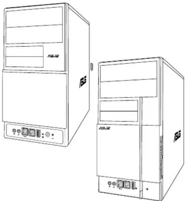
The front panel includes the optical drive bays, floppy disk drive slot, power button, and several I/O ports are located at the front panel.
![graph TD A["Device 1"] --> B["Device 2"] C["Device 3"] --> D["Device 4"] E["Device 5"] --> F["Device 6"] G["Device 7"] --> H["Device 8"] I["Device 9"] --> J["Device 9"] K["ASUS"] --> A K --> C K --> E K --> G style A fill:#f9f,stroke:#333 style C fill:#f9f,stroke:#333 style E fill:#f9f,stroke:#333 s…](/content/2026/06/1344752/images/ffd3bb4c69a306cecc85b9d43a9f9fee7c109e5027e58b545a0823df260b6030.jpg)
- Two empty 5.25-inch bays. These bays are for IDE optical drives.
- 3.5-inch drive bays. These slots are for 3.5-inch floppy or hard disk drives.
- Power button: Press this button to turn the system on.
- Reset button: Press this button to reboot the system without turning off the power.
- HDD LED: This LED lights up when data is read from or written to the hard disk drive.
- USB 2.0 ports: These Universal Serial Bus 2.0 (USB 2.0) ports are available for connecting USB 2.0 devices such as a mouse, printer, scanner, camera, PDA, and others.
- Headphone port: This Line In (green) port connects a headphone with a stereo mini-plug.
- Microphone port: This Mic (pink) port connects a microphone.
- IEEE1394 port

This V-series provides V2/V3 two types of front panel for users to choose. Please refer to your product package for the front panel type you purchased.

PCI Express Graphics Slot supports most of the ATI® and NVIDIA® graphics cards, except some ATI® graphics cards of old version, such as ATI® X300, X550, X700, and X800 series.

An optional Card Reader (see the figure below) is available. It is to be installed in the 3.5-inch drive bay, and connected to the motherboard through a USB cable.

1.3 Rear panel
The system rear panel includes the power connector and several I/O ports that allow convenient connection of devices.

- Power connector: This connector is for the power cable and plug.
- Voltage selector: This switch allows you to adjust the system input voltage according to the voltage supply in your area. See the section "Voltage selector" on page 1-6 before adjusting this switch.
- PS/2 mouse port: This green 6-pin connector is for a PS/2 mouse.
- PS/2 keyboard port: This purple 6-pin connector is for a PS/2 keyboard.
- DVI-out port: This port connects a Digital Visual Interface (DVI-D) card.
- Parallel port: This 25-pin port connects a printer, scanner, or other devices.
- VGA port: This port connects a VGA monitor.
- USB 2.0 ports 1, 2, 3, and 4: These 4-pin Universal Serial Bus (USB) ports are available for connecting USB 2.0 devices.
- Microphone port (pink): This port connects a microphone.
- Line Out port (lime). This port connects a headphone or a speaker. In 4-channel and 6-channel configuration, the function of this port becomes Front Speaker Out.
- Line In port (light blue). This port connects the tape, CD, DVD player, or other audio sources.
- Power supply unit fan vent. This vent is for the PSU fan that provides ventilation inside the power supply unit.
- Chassis fan vent. This vent is for the fan that provides ventilation inside the system chassis.
- IEEE 1394 port. This 6-pin IEEE 1394 port provides high-speed connectivity for audio/video devices, storage peripherals, PCs, or portable devices.
- LAN (RJ-45) port. This port allows Gigabit connection to a Local Area Network (LAN) through a network hub.
- Expansion slot covers. Remove these covers when installing expansion cards.
- Power Switch. This switch is for switching on/off the power supply unit.

Refer to the audio configuration table below for the function of the audio ports in 2, 4, or 6-channel configuration.
Audio 2, 4, or 6-channel configuration
| Port Headset | Headset4-speaker 6-speaker2-speaker | 6-speaker | |
| Light Blue Line In | Surround Out | Surround Out | |
| Lime Line Out Front | Speaker Out | Front Speaker Out | |
| Pink Mic In Mic In | Center/Bass | ||

A HDMI card is available along with the system. It is to be installed on the PCI Express x16 slot on the motherboard. After it is installed, the ports of the HDMI card in the expansion slot area on the rear panel as shown. Refer to the next page for the descriptions for the HDMI card ports.

HDMI card ports
A. HDMI port: This port is for a high-definition multimedia interface (HDMI) connector. B. S-Video port / YPbPr port: This 7-pin port connects any kind of video source via a YPbPr cable or an S-Video cable. C. Video port: This port connects any kind of video source via an RCA cable. D. S/PDIF Output: This port connects an external audio output device via a coaxial S/PDIF cable.
Voltage selector
The PSU has a 115 V/230 V voltage selector switch located beside the power connector. Use this switch to select the appropriate system input voltage according to the voltage supply in your area.
If the voltage supply in your area is 100-127 V, set this switch to 115 V. If the voltage supply in your area is 200-240 V, set this switch to 230 V.
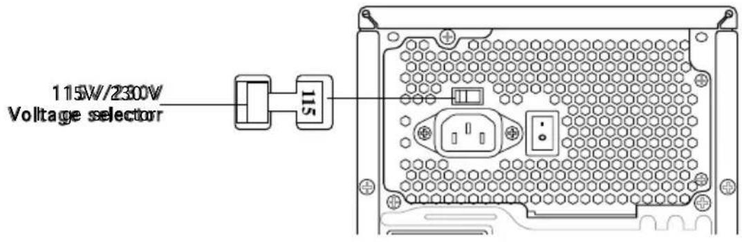

Setting the switch to 115V in a 230V environment or 230V in a 115V environment will seriously damage the system!
1.4 Internal components
The illustration below is the internal view of the system when you remove the top cover and the power supply unit. The installed components are labeled for your reference. Proceed to Chapter 2 for instructions on installing additional system components.

- Front panel cover
- 5.25-inch optical drive bays
- Floppy disk drive bay
- Hard disk drive bay
- Power supply unit
- CPU socket
- DIMM sockets
- ASUS motherboard
- PCI Express x16 slot
- PCI Express x1 slot
- PCI slots
- Metal bracket lock

There is a HDMI module supplying along with the system. Refer to the chapter 2 for the detailed information about the HDMI module.
Chapter 2
This chapter provides step-by-step instructions on how to install components in the system.

Basic installation
2.1 Preparation
Before you proceed, make sure that you have all the components you plan to install in the system.
Basic components to install
- Central Processing Unit (CPU)
- DDR2 Dual Inline Memory Module (DIMM)
- Expansion card(s)
- Hard disk drive
- Optical drive
- Floppy disk drive
Tool
Phillips (cross) screw driver
2.2 Before you proceed
Take note of the following precautions before you install components into the system.

- Use a grounded wrist strap or touch a safely grounded object or a metal object, such as the power supply case, before handling components to avoid damaging them due to static electricity.
- Hold components by the edges to avoid touching the ICs on them.
- Whenever you uninstall any component, place it on a grounded antistatic pad or in the bag that came with the component.
The motherboard comes with an onboard standby power LED. This LED lights up to indicate that the system is ON, in sleep mode or in soft-off mode, and not powered OFF. Unplug the power cable from the power outlet and make sure that the standby power LED is OFF before installing any system component.


Onboard LED
2.3 Removing the side cover and front panel assembly
- Remove the cover screws on the rear panel.
- Pull the side cover toward the rear panel until its hooks disengage from the chassis tab holes. Set the side cover aside.
- Locate the front panel assembly hooks, then lift them until they disengage from the chassis.
- Swing the front panel assembly to the right, until the hinge-like tabs on the right side of the assembly are exposed.
- Remove the front panel assembly, then set aside.

2.4 Central Processing Unit (CPU)
The motherboard comes with a 940-pin AM2 socket designed for the AMD Athlon™ 64 X2/Athlon™ 64/Sempron™ processor.

The AM2 socket has a different pinout from the 940-pin socket designed for the AMD Opteron™ processor. Make sure you use a CPU that is designed for the AM2 socket. The CPU fits in only one correct orientation. DO NOT force the CPU into the socket to prevent bending the connectors on the socket and damaging the CPU!
2.4.11 Installing the CPU
To install a CPU:
- Locate the CPU socket on the motherboard.

- Unlock the socket by pressing the lever sideways, then lift it up to a 90° angle.


Make sure that the socket lever is lifted up to a 90° angle; otherwise, the CPU will not fit in completely.
- Position the CPU above the socket such that the CPU corner with the gold triangle matches the socket corner with a small triangle.
- Carefully insert the CPU into the socket until it fits in place.

Please make sure your CPU is fully plugged-in to reduce abnormal symptoms.
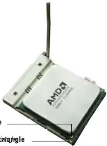
- When the CPU is in place, push down the socket lever to secure the CPU. The lever clicks on the side tab to indicate that it is locked.
- Install a CPU heatsink and fan following the instructions that came with the heatsink package.

2.4.22 Installing the heatsink and fan

Make sure that you use only AMD-certified heatsink and fan assembly.
Follow these steps to install the CPU heatsink and fan.
- Place the heatsink on top of the installed CPU, making sure that the heatsink fits properly on the retention module base.
- The retention module base is already installed on the motherboard upon purchase.
- You do not have to remove the retention module base when installing the CPU or installing other motherboard components.
- If you purchased a separate CPU heatsink and fan assembly, make sure that a Thermal Interface Material is properly applied to the CPU heatsink or CPU before you install the heatsink and fan assembly.


Your boxed CPU heatsink and fan assembly should come with installation instructions for the CPU, heatsink, and the retention mechanism. If the instructions in this section do not match the CPU documentation, follow the latter.
- Attach one end of the retention bracket to the retention module base.

- Align the other end of the retention bracket (near the retention bracket lock) to the retention module base. A clicking sound denotes that the retention bracket is in place.

Make sure that the fan and heatsink assembly perfectly fits the retention mechanism module base, otherwise you cannot snap the retention bracket in place.
- Push down the retention bracket lock on the retention mechanism to secure the heatsink and fan to the module base.
- When the fan and heatsink assembly is in place, connect the CPU fan cable to the connector on the motherboard labeled CPU_FAN.

Do not forget to connect the CPU fan connector! Hardware monitoring errors can occur if you fail to plug this connector.
2.5 Installing a DIMM
The system motherboard comes with four Double Data Rate 2 (DDR2) Dual Inline Memory Module (DIMM) sockets.
The following figure illustrates the location of the sockets:

| Channel Sockets | Sockets |
| Channel A DIMM_A1 and DIMM_A2 | |
| Channel B DIMM_B1 and DIMM_B2 | |
2.5.11 Memory configurations
You may install up to 4 GB system memory using 256 MB, 512 MB, 1 GB, and 2 GB unbuffered ECC/non-ECC DDR2 DIMMs.

- For dual-channel configuration, the total size of memory module(s) installed per channel must be the same (DIMM_A1 + DIMM_A2 = DIMM_B1 + DIMM_B2).
- Always install DIMMs with the same CAS latency. For optimum compatibility, it is recommended that you obtain memory modules from the same vendor. Refer to the DDR2 Qualified Vendors List for details.
- Some odd version DDR2-667 DIMMs may not match Intel On-Die-Temination (ODT) requirement and may downgrade to run at DDR2-533. If this happens, contact your retailer for the ODT value.
- This motherboard does not support memory modules made up of 128 Mb chips.
Qualified Vendors List (QVL)
DDR2-533
| Size | Vendor | Model | Side(s) | Component | Side(s) | B | C | Component | A | B | C |
| 256MB | KINGSTON | E5116AF-5C-E | SS | KVR533D2N4/256 | V | V | V | ||||
| 512MB | KINGSTON | HYB18T512800AF37 | SS | KVR533D2N4/512 | V | V | V | ||||
| 1024MB | KINGSTON | 5YDIID9GCT | DS | KVR533D2N4/1G | V | V | V | ||||
| 512MB | Qimonda | HYB18T512800BF37 | SS | HYS64T64000HU-3.7-B | V | V | V | ||||
| 1024MB | Qimonda | HYB18T512800BF37 | DS | HYS64T128020HU-3.7-B | V | V | V | ||||
| 256MB | SAMSUNG | K4T51163QC-ZCD5 | SS | M378T3354CZ3-CD5 | V | V | V | ||||
| 512MB | SAMSUNG | ZCD5K4T51083QC | SS | M378T6553CZ3-CD5 | V | V | V | ||||
| 1024MB | SAMSUNG | ZCD5K4T51083QC | DS | M378T2953CZ3-CD5 | V | V | V | ||||
| 256MB | Hynix | HY5PS121621CFP-C4 | SS | HYMP532U64CP6-C4 | V | V | V | ||||
| 1024MB | Hynix | HY5PS12821CFP-C4 | DS | HYMP512U64CP8-C4 | V | V | V | ||||
| 256MB | CORSAIR | 32M16CEDG | SS | VS256MB533D2 | V | V | V | ||||
| 512MB | CORSAIR | MI110052432M8CEC | DS | VS512MB533D2 | V | V | V | ||||
| 1024MB | CORSAIR | 64M8CEDG | DS | VS1GB533D2 | V | V | V | ||||
| 512MB | ELPIDA | E5108AB-5C-E(ECC) | SS | EBE51ED8ABFA-5C-E | V | V | V | ||||
| 512MB | ELPIDA | E5108AB-5C-E | SS | EBE51UD8ABFA-5C | V | V | V | ||||
| 512MB | ELPIDA | E5108AB-5C-E | SS | EBE51UD8ABFA-5C-E | V | V | V |
DDR2-667
| Size | Vendor | Model | Side(s) | Component | DIMM Support | ||
| A | B | C | |||||
| 512MB | KINGSTON | D6408TEBGGL3U | SS | KVR667D2N5/512 | V | V | V |
| 1024MB | KINGSTON | D6408TEBGGL3U | DS | KVR667D2N5/1G | V | V | V |
| 256MB | KINGSTON | HYB18T256800AF3S | SS | KVR667D2N5/256 | V | V | |
| 1024MB | Qimonda | HYB18T512800BF3S(ECC) | DS | HYS72T128020HU-3S-B | V | V | V |
| 256MB | Qimonda | HYB18T512160BF-3S | SS | HYS64T32000HU-3S-B | V | V | V |
| 512MB | Qimonda | HYB18T512800BF3S | SS | HYS64T64000HU-3S-B | V | V | V |
| 1024MB | Qimonda | HYB18T512800BF3S | DS | HYS64T128020HU-3S-B | V | V | V |
| 512MB | SAMSUNG | ZCE6K4T51083QC | SS | M378T6553CZ0-CE6 | V | V | V |
| 256MB | SAMSUNG | K4T51163QC-ZCE6 | SS | M378T3354CZ3-CE6 | V | V | V |
| 512MB | SAMSUNG | K4T51083QC | SS | M378T6553CZ3-CE6 | V | V | V |
| 1024MB | SAMSUNG | ZCE6K4T51083QC | DS | M378T2953CZ3-CE6 | V | V | V |
| 256MB | CORSAIR | MIII00605 | SS | VS256MB667D2 | V | ||
| 512MB | CORSAIR | 64M8CFEG | SS | VS512MB667D2 | V | V | V |
| 1024MB | CORSAIR | 64M8CFEG | DS | VS1GB667D2 | V | ||
| 256MB | ELPIDA | E2508AB-6E-E | SS | EBE25UC8ABFA-6E-E | V | V | V |
| 512MB | ELPIDA | E5108AE-6E-E | SS | EBE51UD8AEFA-6E-E | V | V | V |
| 512MB | A-DATA | AD29608A8A-3EG | SS | M2OAD5G3H3166I1C52 | V | V | V |
| 1024MB | A-DATA | AD29608A8A-3EG | DS | M2OAD5G3I4176I1C52 | V | V | |
| 512MB | crucial | Heat-Sink Package | SS | BL6464AA663.8FD | |||
| 1024MB | crucial | Heat-Sink Package | DS | BL12864AA663.16FD | |||
| 1024MB | crucial | Heat-Sink Package | DS | BL12864AL664.16FD | V | V | V |
| 1024MB | crucial | Heat-Sink Package | DS | BL12864AA663.16FD2 | |||
| 512MB | Apacer | AM4B5708GQJS7E0628F | SS | AU512E667C5KBGC | V | ||
| 1024MB | Apacer | AM4B5708GQJS7E | DS | AU01GE667C5KBGC | V | ||
| 256MB | Kingmax | N2TU51216AG-3C | SS | KLCB68F-36KH5 | V | V | V |
| 512MB | Kingmax | KKEA88B4LAUG-29DX | SS | KLCC28F-A8KB5 | V | V | |
| 1024MB | Kingmax | KKEA88B4LAUG-29DX | DS | KLCD48F-A8KB5 | V | ||
| 512MB | Transcend | E5108AE-6E-E | SS | TS64MLQ64V6J | V | V | |
| 1024MB | Transcend | E5108AE-6E-E | DS | TS128MLQ64V6J | V | ||
DDR2-667
| Size | Vendor Model | Side(s) Component | Side(€) | Component | DIMM Support | ||
| A | B | C | |||||
| 512MB | Transcend | J12Q3AB-6 | SS | JM367Q643A-6 | V | V | V |
| 1024MB | Transcend | J12Q3AB-6 | DS | JM388Q643A-6 | |||
| 512MB | Super Talent | Heat-Sink Package | SS | T6UA512C5 | V | ||
| 1024MB | Super Talent | Heat-Sink Package | DS | T6UB1GC5 | V | V | |
| 512MB | SMART | G64M8XB3ITIX4TUE | SS | TB3D2667C58S | V | V | |
| 512MB | SMART | G64M8XB3ITIX4TUE | DS | TB4D2667C58D | V | V | V |
DDR2-800
| Size | Vendor | Model | Side(s) | Component | A | B | C |
| 512MB | KINGSTON | K4T51083QC | SS | KVR800D2N5/512 | V | V | V |
| 1024MB | KINGSTON | Heat-Sink Package | DS | KHX6400D2LL/1G | |||
| 1024MB | KINGSTON | Heat-Sink Package | SS | KHX6400D2LLK2/1GN | V | V | |
| 256MB | Qimonda | HYB18T512160BF-25F | SS | HYS64T32000HU-25F-B | V | V | V |
| 512MB | Qimonda | HYB18T512800BF25F | SS | HYS64T64000HU-25F-B | V | V | |
| 1024MB | Qimonda | HYB18T512800BF25F | DS | HYS64T128020HU-25F-B | V | V | V |
| 512MB | SAMSUNG | EDD339XX | SS | M378T6553CZ3-CE7 | V | V | |
| 256MB | SAMSUNG | K4T51163QC-ZCE7 | SS | M378T3354CZ3-CE7 | V | V | V |
| 512MB | SAMSUNG | ZCE7K4T51083QC | SS | M378T6553CZ3-CE7 | V | V | V |
| 1024MB | Hynix | HY5PS12821CFP-S5 | DS | HYMP512U64CP8-S5 | V | V | V |
| 512MB | MICRON | 5JAIIZ9DQQ | SS | MT8HTF6464AY-80EA3 | V | V | V |
| 1024MB | MICRON | 5JAIIZ9DQQ | DS | MT16HTF12864AY-80EA3 | V | V | V |
| 512MB | MICRON | 5ZD22D9GKX | SS | MT8HTF6464AY-80ED4 | V | V | V |
| 1024MB | MICRON | 5ZD22D9GKX | DS | MT16HTF12864AY-80ED4 | V | V | |
| 512MB | MICRON | 6CD22D9GKX | SS | MT8HTF6464AY-80ED4 | V | V | |
| 1024MB | MICRON | 6CD22D9GKX | DS | MT16HTF12864AY-80ED4 | V | V | V |
| 1024MB | CORSAIR | Heat-Sink Package | DS | CM2X1024-6400C4 | V | V | V |
| 1024MB | ELPIDA | E1108AB-8E-E(ECC) | SS | EBE10EE8ABFA-8E-E | V | V | V |
| 2048MB | ELPIDA | E1108AB-8E-E(ECC) | DS | EBE21EE8ABFA-8E-E | V | V | |
| 512MB | Crucial | Heat-Sink Package | SS | BL6464AA804.8FD | |||
| 512MB | Crucial | Heat-Sink Package | SS | BL6464AA804.8FD3 | V | V | V |
| 1024MB | Crucial | Heat-Sink Package | DS | BL12864AA804.16FD | V | ||
| 1024MB | Crucial | Heat-Sink Package | DS | BL12864AL804.16FD3 | V | V | V |
| 1024MB | Crucial | Heat-Sink Package | DS | BL12864AA804.16FD3 | V | V | V |
| 512MB | Apacer | Heat-Sink Package | DS | AHU512E800C5K1C | V | ||
| 1024MB | Apacer | Heat-Sink Package | DS | AHU01GE800C5K1C | V | V | V |
| 512MB | Transcend | K4T51083QC | SS | TS64MLQ64V8J | V | V | V |
| 1024MB | Transcend | K4T51083QC | DS | TS128MLQ64V8J | V | V | V |
| 512MB | KINGMAX | KKEA88B4LZUG-25DF | SS | KLDC28F-A8KB5 | |||
| 1024MB | KINGMAX | KKEA88B4LZUG-25DF | DS | KLDD48F-A8KB5 | V | V | V |
Side(s): SS - Single-sided DS - Double-sided
CL: CAS Latency
DIMM support:
A - Supports one module inserted into either slot, in Single-channel memory configuration.
B - Supports one pair of modules inserted into both slots as one pair of Dual-channel memory configuration.
2.5.2 Installing a DDR2 DIMM

Make sure to unplug the power supply before adding or removing DIMMs or other system components. Failure to do so may cause severe damage to both the motherboard and the components.
- Unlock a DDR2 DIMM socket by pressing the retaining clips outward.
- Align a DIMM on the socket such that the notch on the DIMM matches the break on the socket.
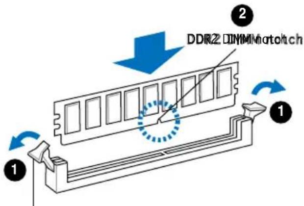
Unlocked retaining clip

A DDR2 DIMM is keyed with a notch so that it fits in only one direction. DO NOT force a DIMM into a socket to avoid damaging the DIMM.
- Firmly insert the DIMM into the socket until the retaining clips snap back in place and the DIMM is properly seated.
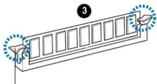
Locked retaining clip
2.5.3 Removing a DDR2 DIMM
Follow these steps to remove a DIMM.
- Simultaneously press the retaining clips outward to unlock the DIMM.


Support the DIMM lightly with your fingers when pressing the retaining clips. The DIMM might get damaged when it flips out with extra force.
- Remove the DIMM from the socket.
2.6 Expansion slots
In the future, you may need to install expansion cards. The following sub-sections describe the slots and the expansion cards that they support.

Make sure to unplug the power cord before adding or removing expansion cards. Failure to do so may cause you physical injury and damage motherboard components.

PCI Express Graphics Slot supports most of the ATi® and NVIDIA® graphics cards, except some ATi® graphics cards of old version, such as ATi® X300, X550, X700, and X800 series.
2.6.1 Installing an expansion card
To install an expansion card:
- Before installing the expansion card, read the documentation that came with it and make the necessary hardware settings for the card.
- Remove the system unit cover (if your motherboard is already installed in a chassis).
- Remove the bracket opposite the slot that you intend to use. Keep the screw for later use.
- Align the card connector with the slot and press firmly until the card is completely seated on the slot.
- Secure the card to the chassis with the screw you removed earlier.
- Replace the system cover.
2.6.22 Configuring expansion card
After installing the expansion card, configure it by adjusting the software settings.
- Turn on the system and change the necessary BIOS settings, if any. See Chapter 5 for information on BIOS setup.
- Assign an IRQ to the card. Refer to the tables on the next page.
- Install the software drivers for the expansion card.
Standard interrupt assignments
IRQ Standard Function
| 0 System Timer |
| 1 Keyboard Controller |
| 2 Re-direct to IRQ#9 |
| 4 Communications Port (COM1)* |
| 5 IRQ holder for PCI steering* |
| 6 Floppy Disk Controller |
| 7 Printer Port (LPT1)* |
| 8 System CMOS/Real Time Clock |
| 9 IRQ holder for PCI steering* |
| 10 IRQ holder for PCI steering* |
| 11 IRQ holder for PCI steering* |
| 12 PS/2 Compatible Mouse Port* |
| 13 Numeric Data Processor |
| 14 Primary IDE Channel |
| 15 Secondary IDE Channel |
* These IRQs are usually available for PCI devices.
IRQ assignments for this motherboard
| A B C D E F G H | A | B | C | D | E | F | G | H |
| PCI slot 1 | shared | — | — | — | — | — | — | — |
| PCI slot 2 | — | shared | — | — | — | — | — | — |
| PCI Express x16 slot | shared | — | — | — | — | — | — | — |
| PCI Express x1 slot | — | shared | — | — | — | — | — | — |
| Onboard USB controller 1 | — | — | — | — | — | — | — | shared |
| Onboard USB controller 2 | — | — | — | shared | — | — | — | — |
| Onboard USB controller 3 | — | — | shared | — | — | — | — | — |
| Onboard USB controller 4 | — | — | — | shared | — | — | — | — |
| Onboard USB 2.0 controller | — | — | — | — | — | — | — | shared |
| Onboard IDE port | — | — | — | shared | — | — | — | — |
| Onboard HD audio | shared | — | — | — | — | — | — | — |
| Onboard LAN | — | shared | — | — | — | — | — | — |

When using PCI cards on shared slots, ensure that the drivers support "Share IRQ" or that the cards do not need IRQ assignments. Otherwise, conflicts will arise between the two PCI groups, making the system unstable and the card inoperable.
2.6.3 PCI Express x1 slot
This motherboard supports PCI Express x1 network cards, SCSI cards and other cards that comply with the PCI Express specifications. The figure shows a network card installed on the PCI Express x1 slot.

2.6.4 PCI Slots
The PCI slots support cards such as a LAN card, SCSI card, USB card, and other cards that comply with PCI specifications. The figure shows a LAN card installed on a PCI slot.

2.6.5 PCI Express x16 slot
This motherboard supports PCI Express x16 graphic cards that comply with the PCI Express specifications. The figure shows a graphics card installed on the PCI Express x16 slot.


There is a HDMI card supplying along with the system. The HDMI card is to be connected to the onboard PCI Express x16 slot.
2.7 Installing an optical drive
Refer to the instructions in this section if you wish to install a new optical drive.
Follow these steps to install an optical drive:
- Place the chassis upright.
- Remove the drive slot metal plate cover.
- Insert the optical drive into the upper 5.25-inch drive bay and carefully push the optical drive into the bay until its screw holes align with the holes on the bay as shown.
- Secure the optical drive with two screws on both sides of the bay.

- Connect a power cable from the power supply to the power connector at the back of the optical drive.
- Connect one end of the IDE ribbon cable to the IDE interface at the back of the optical drive, matching the red stripe on the cable with Pin 1 on the IDE interface.
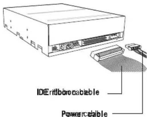
- Connect the other end of the IDE ribbon cable to the primary IDE connector (labeled PRI_IDE) on the motherboard.
- Remove the dummy drive slot cover from the front panel.
- Replace the front panel.
2.8 Installing a hard disk drive
To install a Serial ATA hard disk drive:
- Carefully place the hard disk into the lowest 3.5-inch drive slot (without the metal plate cover).
- Fasten the screws to secure the hard disk to the drive slot.
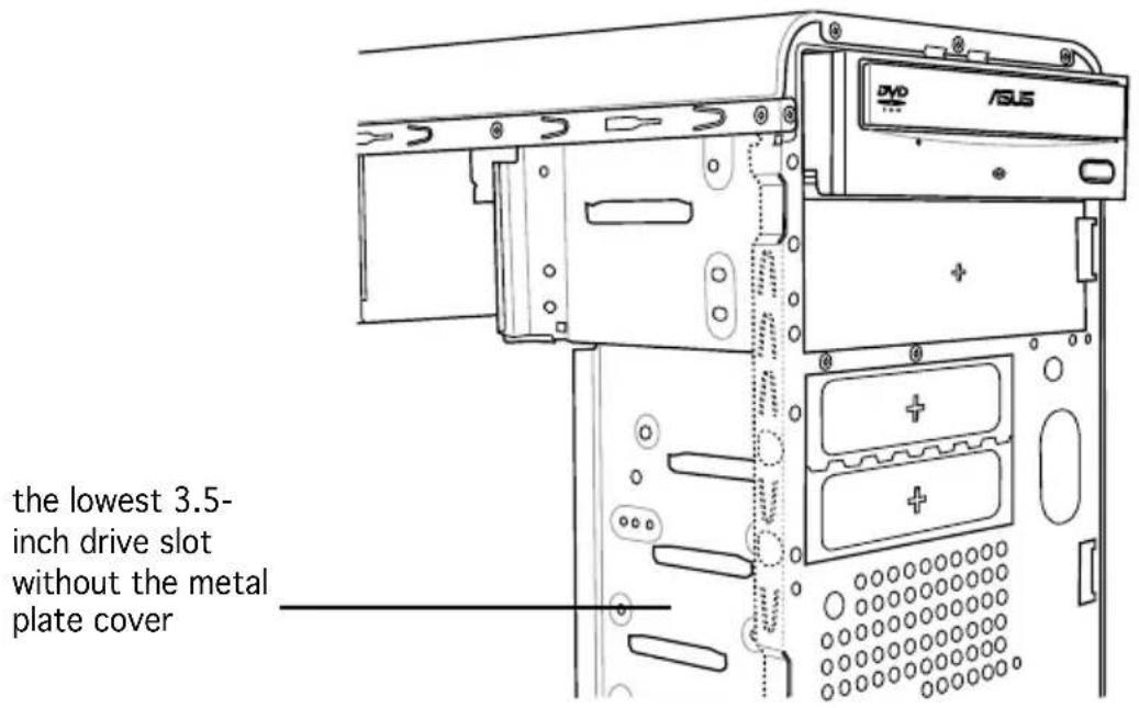

If you do not need to install the optional card reader into your system, you can install the HDD in one of the 3.5-inch external bays (with the metal plate cover).
- Connect one end of the Serial ATA cable to the SATA connector at the back of the drive, then connect the other end to a Serial ATA connector on the motherboard. See page 4-6 for the location of the Serial ATA connectors.
- Connect a 15-pin Serial ATA power plug from the power supply unit to the 15-pin power connector at the back of the drive.
- OR -
Connect a 4-pin (female) power plug from the power supply unit to the 4-pin (male) power connector at the back of the drive.
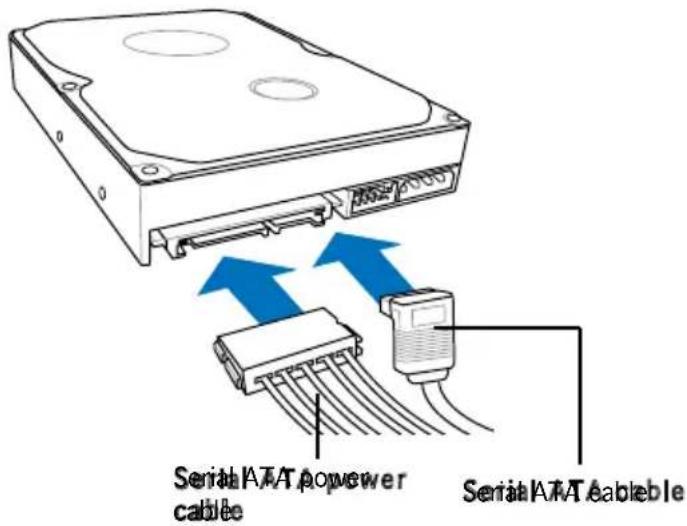

If your Serial ATA HDD has both 4-pin and 15-pin connectors at the back, use either the 15-pin SATA power adapter plug OR the legacy 4-pin power connector. DO NOT use both to prevent damage to components and to keep the system from becoming unstable.
To install an IDE hard disk drive:
- Follow steps 1-2 of the previous section.
- Connect the blue interface of the IDE ribbon cable to the primary IDE connector (blue connector labeled PRI_IDE) on the motherboard. See page 4-7 for the location of the connector.


- If you will install only one hard disk drive, make sure to configure your hard disk drive as Master device before connecting the IDE cable and power plug. Refer to the HDD documentation on how to set the drive as a Master device.
- If you will install two IDE hard disk drives, configure the other device as Slave.
- Connect the gray interface of the IDE ribbon cable to the IDE connector on the drive.
- If you install two IDE hard disk drives, connect the black interface of the IDE ribbon cable to the IDE connector on the second (Slave) IDE hard disk drive.
- Connect a 4-pin power plug from the power supply unit to the power connector at the back of the drive(s).
2.9 Installing the card reader
An optional card reader module (see the figure below) is available with the system. If you want to install the card reader into your system, follow the steps on the next page.

To install the card reader module:
- Remove the drive slot metal plate cover.
- Carefully insert the card reader module into the 3.5-inch bay until the screw holes align with the holes on the bay.
- Secure the card reader module with two screws on both sides.

- Connect the USB cable of the card reader to the USB connector on the motherboard.
2.10 Installing a floppy disk drive
The Vintage2-PE2 system comes with one 3.25-inch drive bay for a floppy disk drive.
To install a floppy disk drive:
- Remove the drive slot metal plate cover.

- Carefully insert the floppy disk drive into the floppy drive bay until the screw holes align with the holes on the bay.
- Secure the floppy disk drive with two screws on both sides.

- Connect the floppy disk drive signal cable to the signal connector at the back of the drive.

- Connect the other end of the signal cable to the floppy disk drive connector on the motherboard. See page 4-6 for the location of the floppy disk drive connector.
- Connect a 4-pin power cable from the power supply unit to the power connector at the back of the floppy disk drive.
2.11 Re-connecting cables
You may have disconnected some cables when you were installing components. You must re-connect these cables before you replace the chassis cover.
LED cables
![graph TD A["PowerLED"] --> B["PowerSwitch"] B --> C["HDDLEED"] C --> D["Reset button"] style A fill:#f9f,stroke:#333 style B fill:#ccf,stroke:#333 style C fill:#cfc,stroke:#333 style D fill:#fcc,stroke:#333 subgraph PowerLED E["IKE LED"] F["PWR LED"] end subgraph PowerSwitch G["IKE LED"] H["PWR LED"…](/content/2026/06/1344752/images/08e3b781ce0b732eb16206cf034c75bdebd4f6561e87cf66fa960e30979e3203.jpg)

Connect the reset button, power switch, power LED, and HDD LED cables to their respective leads in the system panel connector on the motherboard.
2.12 Reinstalling the cover
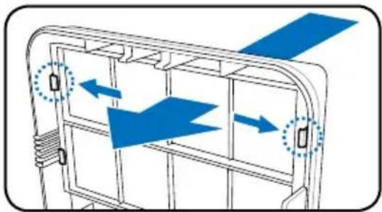
If you installed an optical and/or floppy disk drive, remove the bay cover(s) on the front panel assembly before reinstalling it to the chassis. To do this:
- Locate the bay cover locks.
- Press the locks outward to release the bay cover.
- Push the bay cover inward, then set it aside.
- Follow the same instructions to remove the 3.5" drive bay cover.
To reinstall the front panel assembly and side cover:
- Insert the front panel assembly hinge-like tabs into the holes on the right side of the chassis.
- Swing the front panel assembly to the left, then insert the hooks into the chassis until the front panel assembly fits in place.
- Insert the six side cover hooks into the chassis tab holes.
- Push the side cover toward the front panel until it fits in place.
- Secure the cover with the two screws you removed earlier.

If the air duct interferes with the CPU fan, adjust the air duct accordingly.

Chapter 3
This chapter helps you power up the system and install drivers and utilities from the support CD.

Starting up
3.1 Installing an operating system
The barebone system supports Windows® 2000/XP operating systems (OS). Always install the latest OS version and corresponding updates so you can maximize the features of your hardware.

Because motherboard settings and hardware options vary, use the setup procedures presented in this chapter for general reference only. Refer to your OS documentation for more information.

- Windows XP OS setup cannot recognize Serial ATA hard drives without the necessary drivers. Use the bundled floppy disk when installing Windows XP OS to a Serial ATA hard drive.
- From the Windows XP setup screen, press F6 when prompted then follow succeeding screen instructions to install the SATA drivers.
3.2 Powering up
Press the system power button (⏻) to enter the OS.

3.3 Support CD information
The support CD that came with the system contains useful software and several utility drivers that enhance the system features.

- Screen display and driver options may not be the same for different operating system versions.
- The contents of the support CD are subject to change at any time without notice. Visit the ASUS website for updates.
3.3.1 Running the support CD
To begin using the support CD, place the CD in your optical drive. The CD automatically displays the Drivers menu if Autorun is enabled in your computer.


If Autorun is NOT enabled in your computer, browse the contents of the support CD/DVD to locate the file ASSETUP.EXE from the BIN folder. Double-click the ASSETUP.EXE to run the CD/DVD.
The drivers menu shows the available device drivers if the system detects installed devices. Install the necessary drivers to activate the devices.
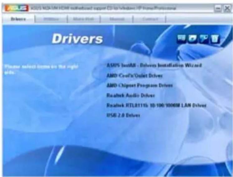
ASUS InstAll Driver Installation Wizard
Launches the ASUS InstAll driver installation wizard.
AMD Cool 'n' Quiet Driver
Installs the AMD Cool 'n' Quiet driver.
AMD Chipset Program Driver
Installs the AMD chipset program driver.
Realtek Audio Driver
Installs the Realtek® ALC883 audio driver and application.
Realtek RTL8111B 10/100/1000M LAN Driver
Installs the Realtek® RTL8111B 10/100/1000M LAN driver.
USB 2.0 Driver
Installs the USB 2.0 driver.

The screen display and drivers option may not be the same for different operating system versions.
3.3.3 Utilities menu
The Utilities menu shows the applications and other software that the motherboard supports.

ASUS InstAll Installation Wizard for Utilities
Launches the ASUS InstAll utilities installation wizard.
ASUS Cool 'n' Quiet Utility
This item installs the ASUS Cool 'n' Quiet utility.
ASUS Update
The ASUS Update utility allows you to update the motherboard BIOS in a Windows® environment. This utility requires an Internet connection either through a network or an Internet Service Provider (ISP).
ASUS PC Probe II
This smart utility monitors the fan speed, CPU temperature, and system voltages, and alerts you of any detected problems. This utility helps you keep your computer in healthy operating condition.
ASUS Music Alarm
The ASUS Music Alarm is an audio alarm clock that uses your favorite CD music to give you a personal wake-up call.

The screen display and utilities option may not be the same for different operating system versions.
ATI WebBAM Utility
This utility allows you to configure Serial ATA (SATA) RAID/AHCI drive disk. For more detailed instructions, refer to the RAID manual in the support

This item appears only when you set the Onboard SATA Type item in the BIOS to [RAID Controller]. See page 2-25 for details.
3.3.4 Make Disk menu
The Make Disk menu allows you to make a RAID driver disk.

Make ATI RAID/AHCI Driver
Allows you to create an ATI® Serial ATA (SATA) RAID/AHCI driver disk.
Make ATI RAID/AHCI Vista Driver
Allows you to create an ATI® Serial ATA (SATA) RAID/AHCI driver disk for Windows® Vista Operating System (OS).
3.3.5 Manual menu
The Manual menu contains a list of supplementary user manuals. Click an item to open the folder of the user manual.

Most user manual files are in Portable Document Format (PDF). Install the Adobe® Acrobat® Reader from the Utilities menu before opening a user manual file.

3.3.6 ASUS Contact information
Click the Contact tab to display the ASUS contact information. You can also find this information on the inside front cover of this user guide.
3.4 Software information
Most of the applications in the support CD have wizards that will conveniently guide you through the installation. View the online help or readme file that came with the software for more information.
ASUS PC Probe II
PC Probe II is a utility that monitors the computer's vital components and alerts you of any problem with these components. PC Probe II senses fan rotations, CPU temperature, and system voltages, among others. PC Probe II is software-based, allowing you to start monitoring your computer the moment you turn it on. With this utility, you are assured that your computer is always at a healthy operating condition.
Installing PC Probe II
To install PC Probe II on your computer:
- Place the support CD into the optical drive. The Drivers installation tab appears if your computer has Autorun enabled.

If Autorun is not enabled on your computer, browse the contents of the support CD to locate the setup.exe file in the ASUS PC Probe II folder. Double-click the setup.exe file to start installation.
- Click the Utilities tab, then click ASUS PC Probe II.
- Follow the on-screen instructions to complete the installation.
Launching PC Probe II
You can launch PC Probe II immediately after installation or anytime from the Windows® desktop.
To launch PC Probe II from the Windows® desktop, click Start > All
Programs > ASUS > PC Probe II. The PC Probe II main window appears.
After launching the application, the PC Probe II icon appears in the Windows® taskbar. Click this icon to close or restore the application.

Using PC Probe II
Main window
The PC Probe II main window allows you to view the current status of your system and change the utility configuration. By default, the main window displays the Preference section. You can close or restore the Preference section by clicking on the triangle on the main window right handle.
Button Function
Opens the Configuration window
Opens the Report window
Opens the Desktop Management Interface window
Opens the Peripheral Component Interconnect window
Opens the Windows Management Instrumentation window
Opens the hard disk drive, memory, CPU usage window
Shows/Hides the Preference section
Minimizes the application
Windows Management Instrumentation window
Opens the hard disk drive, memory, CPU usage window
Shows/Hides the
Preference section
Minimizes the application
Closes the application
Sensor alert
When a system sensor detects a problem, the main window right handle turns red, as the illustrations below show.


When displayed, the monitor panel for that sensor also turns red. Refer to the Monitor panels section for details.
Preferences
You can customize the application using the Preference section in the main window. Click the box before each preference to activate or deactivate.

Hardware monitor panels
The hardware monitor panels display the current value of a system sensor such as fan rotation, CPU temperature, and voltages.
The hardware monitor panels come in two display modes: hexagonal (large) and rectangular (small). When you check the Enable Monitoring Panel option from the Preference section, the monitor panels appear on your computer's desktop.

Large display

Small display
Changing the monitor panels position
To change the position of the monitor panels on the desktop, click the arrow down button of the Scheme options, then select another position from the list box. Click OK when finished.

Moving the monitor panels
All monitor panels move together using a magnetic effect. If you want to detach a monitor panel from the group, click the horseshoe magnet icon. You can now move or reposition the panel independently.

Adjusting the sensor threshold value You can adjust the sensor threshold value in the monitor panel by clicking the arrow buttons. You can also adjust the threshold values using the Config window.
You cannot adjust the sensor threshold values in a small monitoring panel.

Monitoring sensor alert
The monitor panel turns red when a component value exceeds or is lower than the threshold value. Refer to the illustrations below.

Large display

Small display
WMI browser
Click to display the WMI (Windows Management Instrumentation) browser. This browser displays various Windows® management information. Click an item from the left panel to display on the right panel. Click the plus sign (+) before WMI Information to display the available information.


You can enlarge or reduce the browser size by dragging the bottom right corner of the browser.
DMI browser
Click to display the DMI (Desktop Management Interface) browser. This browser displays various desktop and system information. Click the plus sign (+) before DMI Information to display the available information.

PCI browser
Click to display the PCI (Peripheral Component Interconnect) browser. This browser provides information on the PCI devices installed on your system. Click the plus sign (+) before the PCI Information item to display available information.

Usage
The Usage browser displays real-time information on the CPU, hard disk drive space, and memory usage. Click to display the Usage browser.
CPU usage
The CPU tab displays real-time CPU usage in a line graph representation. If the CPU has Hyper-Threading enabled, two separate line graphs display the operation of the two logical processors.

Hard disk drive space usage
The Hard Disk tab displays the used and available hard disk drive space. The left panel of the tab lists all logical drives. Click a hard disk drive to display the information on the right panel. The pie chart at the bottom of the window represents the used (blue) and the available HDD space.

Memory usage
The Memory tab shows both used and available physical memory. The pie chart at the bottom of the window represents the used (blue) and the available physical memory.

Configuring PCProbe II
Click to view and adjust the sensor threshold values.
The Config window has two tabs: Sensor/Threshold and Preference. The Sensor/Threshold tab enables you to activate the sensors or to adjust the sensor threshold values. The Preference tab allows you to customize sensor alerts, change temperature scale, or enable the Q-Fan feature.

Chapter 4
This chapter gives information about the motherboard that comes with the system. This chapter includes the motherboard layout, jumper settings, and connector locations.

Motherboard introduction
4.1 Introduction
The Vintage V-Series M2A690G barebone system comes with an ASUS motherboard. This chapter provides technical information about the motherboard for future upgrades or system reconfiguration.
4.2 Motherboard layout

4.3 Jumpers
1. Clear RTC RAM (CLRTC)
This jumper allows you to clear the Real Time Clock (RTC) RAM in CMOS. You can clear the CMOS memory of date, time, and system setup parameters by erasing the CMOS RTC RAM data. The onboard button cell battery powers the RAM data in CMOS, which includes system setup information such as system passwords.
To erase the RTC RAM:
- Turn OFF the computer and unplug the power cord.
- Remove the onboard battery.
- Move the jumper cap from pins 1-2 (default) to pins 2-3. Keep the cap on pins 2-3 for about 5~10 seconds, then move the cap back to pins 1-2.
- Re-install the battery.
- Plug the power cord and turn ON the computer.
- Hold down the key during the boot process and enter BIOS setup to re-enter data.

Except when clearing the RTC RAM, never remove the cap on CLRTC jumper default position. Removing the cap will cause system boot failure!


You do not need to clear the RTC when the system hangs due to overclocking. For system failure due to overclocking, use the C.P.R. (CPU Parameter Recall) feature. Shut down and reboot the system so the BIOS can automatically reset parameter settings to default values.
2. USB device wakeup (3-pin USBPW1234, USBPW5678, USBPW910)
Set these jumpers to +5V to wake up the computer from S1 sleep mode (CPU stopped, DRAM refreshed, system running in low power mode) using the connected USB devices. Set to +5VSB to wake up from S3 and S4 sleep modes (no power to CPU, DRAM in slow refresh, power supply in reduced power mode).
The USBPW1234 jumper is for the rear USB ports. The USBPW5678 jumper is for the internal USB connectors that you can connect to additional USB ports.
![graph TD A["USB Device Wake Up"] --> B["USB PWR1-4"] B --> C["+5V (Default)"] B --> D["+5VSB"] E["USB PWR910"] --> F["+5V (Default)"] E --> G["+5VSB"] H["USB PWR1-4"] --> I["1 2"] H --> J["2 3"] K["USB PWR910"] --> L["1 2"] K --> M["2 3"] N["USB PWR910"] --> O["1 2"] N --> P["2 3"]](/content/2026/06/1344752/images/1544d188d1217b1722673f54519611e8e35f3a71ce5ecf4bf2dc9d46ac39e787.jpg)

- The USB device wake-up feature requires a power supply that can provide 500 mA on the +5VSB lead for each USB port; otherwise, the system would not power up.
- The total current consumed must NOT exceed the power supply capability (+5VSB) whether under normal condition or in sleep mode.
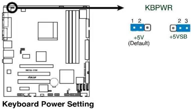
2. Keyboard power (3-pin KBPWR)
This jumper allows you to enable or disable the keyboard wake-up feature. Set this jumper to pins 2-3 (+5VSB) to wake up the computer when you press a key on the keyboard (the default is the Space Bar). This feature requires an ATX power supply that can supply at least 500 mA on the +5VSB lead, and a corresponding setting in the BIOS.
4.4 Connectors
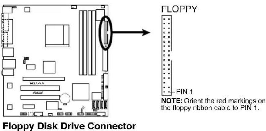
1. Floppy disk drive connector (34-pin FLOPPY)
This connector is for the provided floppy disk drive (FDD) signal cable. Insert one end of the cable to this connector, then connect the other end to the signal connector at the back of the floppy disk drive.

Pin 5 on the connector is removed to prevent incorrect cable connection when using an FDD cable with a covered Pin 5.
2. IDE Connectors (40-pin IDE)
The onboard IDE connectors are for Ultra DMA 100/66/33 signal cables. There are three connectors on each Ultra DMA 100/66/33 signal cable: blue, black, and gray. Connect the blue connector to the motherboard's IDE connector, then select one of the following modes to configure your device(s).

| Drive jumper setting of device(s) | Driver Cableper connector | Mode of device(s) | Cable connector |
| Single device | Cable-Select or Master - Black | ||
| Two devices | Cable-Select Master Black Slave | Gray | |
| Master Slave | Master Slave | Black or gray |

- Pin 20 on the IDE connector is removed to match the covered hole on the Ultra DMA cable connector. This prevents incorrect insertion when you connect the IDE cable.
- Use the 80-conductor IDE cable for Ultra DMA 100/66/33 IDE devices.

If any device jumper is set as "Cable-Select," make sure all other device jumpers have the same setting.
3. Serial ATA connectors (7-pin SATA1, SATA2, SATA3, SATA4)
These connectors are for the Serial ATA signal cables for Serial ATA hard disk drives.

Connect the right-angle side of the SATA signal cable to the SATA device. Alternatively, you may connect the right-angle side of the SATA cable to the onboard SATA port to avoid mechanical conflict with a long card in the PCI2 slot.
right angle side

4. Serial port connector (10-1 pin COM2) COM2
This connector is for a serial (COM) port. Connect the serial port module cable to this connector, then install the module to a slot opening at the back of the system chassis.


The COM module is purchased separately.
5. CPU, Power and Chassis fan connectors
(4-pin CPU_FAN, 4-pin CHA_FAN, 3-pin PWR_FAN, 3-pin R_FAN)
The fan connectors support cooling fans of a total of 1A~2.2A (26.4W max.) at +12V. Connect the fan cables to the fan connectors on the motherboard, making sure that the black wire of each cable matches the ground pin of the connector.


Do not forget to connect the fan cables to the fan connectors. Insufficient air flow inside the system may damage the motherboard components. These are not jumpers! DO NOT place jumper caps on the fan connectors.
6. IEEE 1394a port connection (10-1 pin IE1394_2)
This connector is for an IEEE 1394a port. Connect the IEEE 1394a module cable to this connector, then install the module to a slot opening at the back of the system chassis.


Never connect a USB cable to the IEEE 1394a connector. Doing so will damage the motherboard!

The IEEE 1394 module is purchased separately.
7. ATX power connectors
(24-pin EATXPWR and 4-pin ATX12V)
These connectors are for ATX power supply plugs. The power supply plugs are designed to fit these connectors in only one orientation. Find the proper orientation and push down firmly until the connectors completely fit.

- Do not forget to connect the 4-pin ATX +12 V power plug; otherwise, the system will not boot.
- Use of a PSU with a higher power output is recommended when configuring a system with more power-consuming devices. The system may become unstable or may not boot up if the power is inadequate.
- Make sure that your power supply unit (PSU) can provide at least the minimum power required by your system.
- If you intend to use a PSU with 20-pin and 4-pin power plugs, make sure that the 20-pin power plug can provide at least 15A on +12V and that the PSU has a minimum power rating of 350 W. The system may become unstable or may not boot up if the power is inadequate.
- The ATX 12 V Specification 2.0-compliant PSU passed the motherboard power requirement test with the following configuration:
CPU : Intel
® Pentium® 4 3.6 GHz
Memory : 512 MB DDR (x 4)
Graphics card : PCI Express x16 Nvidia EN5900
Parallel ATA devices : IDE hard disk drive (x 2)
Serial ATA device : SATA hard disk drive
Optical drive : CD-ROM (x2)
SCSI devices : SCSI card and SCSI hard disk drive
- You must install a PSU with a higher power rating if you intend to install additional devices.

ATX Power Connector
EATXPWR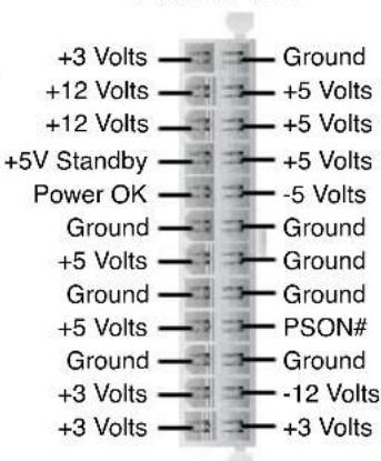
8. Optical drive audio connector (4-pin CD1)
This connector is for the 4-pin audio cable that connects to the audio connector at the back of the optical drive.


Enable the CD-IN function in the audio utility when using this connector.
9. USB connectors (10-1 pin USB56, USB78, USB910)
These connectors are for USB 2.0 ports. Connect the USB module cable to any of these connectors, then install the module to a slot opening at the back of the system chassis. These USB connectors comply with USB 2.0 specification that supports up to 480 Mbps connection speed.

USB 2.0 Connectors

Never connect a 1394 cable to the USB connectors. Doing so will damage the motherboard!

The USB module is purchased separately.
11. Front panel audio connector (10-1 pin AAFP)
This connector is for a chassis-mounted front panel audio I/O module that supports HD Audio standard.


- We recommend that you connect a high-definition front panel audio module to this connector to avail of the motherboard's high-definition audio capability.
13. System panel connector (12-pin PANEL)
This connector supports several chassis-mounted functions.

System Panel Connector
• System power LED (2-pin PLED)
This 2-pin connector is for the system power LED. Connect the chassis power LED cable to this connector. The system power LED lights up when you turn on the system power, and blinks when the system is in sleep mode.
- Hard disk drive activity (2-pin HDLED)
This 2-pin connector is for the HDD Activity LED. Connect the HDD Activity LED cable to this connector. The IDE LED lights up or flashes when data is read from or written to the HDD.
• System warning speaker (4-pin SPEAKER)
This 4-pin connector is for the chassis-mounted system warning speaker. The speaker allows you to hear system beeps and warnings.
• Power/Soft-off button (2-pin PWRSW)
This connector is for the system power button. Pressing the power button turns the system ON or puts the system in SLEEP or SOFT-OFF mode depending on the BIOS settings. Pressing the power switch for more than four seconds while the system is ON turns the system OFF.
- Reset button (2-pin RESET)
This 2-pin connector is for the chassis-mounted reset button for system reboot without turning off the system power.
14. Ports on the HDMI module
This module contains four ports, allowing you to connect any kind of video/audio source to your system. Connect the HDMI module to the onboard PCI Express x16 slot and the HDMI module cable to the onboard YUV/SPDIF_OUT connector.

- Refer to page 1-29 for the position of the onboard YUV/SPDIF_OUT connector. - After installing the HDMI module, make sure the audio device of Sound playback is HDMI Audio rear output (the name may be different based on the OS). Go to Start > Control Panel > Sounds and Audio Devices > Sound Playback to configure the setting.

a. HDMI port. This port is for a high-definition multimedia interface (HDMI) connector.
b. S-Video port / YPbPr port. This 7-pin port connects any kind of video source via a YPbPr cable or an S-Video cable.

c. Video port. This port connects any kind of video source via an RCA cable.
d. S/PDIF Out port. This port connects an external audio output device via a coaxial S/PDIF cable.

- The YPbPr cable, RCA cable and the S-Video cable are purchased separately. - Simultaneous output for YPbPr, AV, S, and RGB is not supported.
Dual display table
This table indicates two corresponding displays when you connect two monitors on any two of the following ports.
| Onboard VGA ports HDMI module ports | |||
| DVI RGB HDMI TV (S-Video/ | Video/YPbPr) | ||
| • | • | ||
| • | • | ||
| • | • | ||
| • | • | ||
| • | • | ||
Playback of HD DVD and Blu-Ray Discs
The speed and bandwidth of the CPU/Memory, DVD player, and drivers will affect the playback quality. Following is a configuration example for your reference. Using the CPU/Memory of higher speed and bandwidth with the higher-version DVD player and drivers will upgrade the playback quality.
CPU - AMD 3800+ X2 Dual Core
Memory - 2 x 1GB of DDR2-800 (Dual channel mode)
Playback software - CyberLink PowerDVD V.7.3
| File Format | Suitable resolution | |
| XP Vista | ||
| Non protected clips 1920 x 1080p 1920 x 1080p | ||
| HD-DVD VC1 1920 x 1080i 1280 x 720p | ||
| Blu-Ray MPEG2 1280 x 720p 1280 x 720p | ||
Chapter 5
This chapter tells how to change system settings through the BIOS Setup menus and describes the BIOS parameters.

5.1 Managing and updating your BIOS
The following utilities allow you to manage and update the motherboard Basic Input/Output System (BIOS) setup.
- ASUS EZ Flash 2 (Updates the BIOS using a floppy disk, USB Flash, or the motherboard support CD during POST.)
- Award BIOS Flash Utility (Updates the BIOS in DOS mode using a bootable floppy disk.)
- ASUS CrashFree BIOS 3 (Updates the BIOS using a bootable floppy, USB Flash disk, or the motherboard support CD when the BIOS file fails or gets corrupted.)
- ASUS Update (Updates the BIOS in Windows® environment.)
Refer to the corresponding sections for details on these utilities.

Save a copy of the original motherboard BIOS file to a bootable floppy disk in case you need to restore the BIOS in the future. Copy the original motherboard BIOS using the ASUS Update or AFUDOS utilities.
5.1.11 Creating a bootable floppy disk
- Do either one of the following to create a bootable floppy disk. DOS environment
a. Insert a 1.44MB floppy disk into the drive. b. At the DOS prompt, type format A:/S then press . Windows® XP environment a. Insert a 1.44 MB floppy disk to the floppy disk drive. b. Click Start from the Windows® desktop, then select My Computer. c. Select the 3 1/2 Floppy Drive icon. d. Click File from the menu, then select Format. A Format 3 1/2 Floppy Disk window appears. e. Select Create an MS-DOS startup disk from the format options field, then click Start. Windows® 2000 environment
To create a set of boot disks for Windows® 2000:
a. Insert a formatted, high density 1.44 MB floppy disk into the drive. b. Insert the Windows® 2000 CD to the optical drive. c. Click Start, then select Run. d. From the Open field, type
D:\bootdisk\makeboot a:
assuming that D: is your optical drive.
e. Press , then follow screen instructions to continue.
- Copy the original or the latest motherboard BIOS file to the bootable floppy disk.
5.1.22 ASUS EZ Flash 2 utility
The ASUS EZ Flash 2 feature allows you to update the BIOS without having to go through the long process of booting from a floppy disk and using a DOS-based utility. The EZ Flash 2 utility is built into the BIOS chip, so it is accessible by pressing <Alt+F2> during the Power-On Self-Test (POST).
To update the BIOS using EZ Flash 2:
- Visit the ASUS website (www.asus.com) to download the latest BIOS file for the motherboard.
- Save the BIOS file to a floppy disk or a USB flash disk, then restart the system.
- You can launch the EZ Flash 2 by two methods.
(1) Insert the floppy disk / USB flash disk that contains the BIOS file into the floppy disk drive or the USB port.
Press <Alt+F2> during POST to display the following.
![ASUSTek EZ Flash 2 BIOS ROM Utility V3.00 FLASH TYPE: Winbond W39V040C/FC (4MB) Current ROM BOARD: M2A-VM VER: 0103 DATE: 08/25/2006 Update ROM BOARD: Unknown VER: Unknown DATE: Unknown PATH: A:\ A: Note [Enter] Select or Load [B] Backup [ESC] Exit [Tab] Switch [Up/Down/Home/End] Move](/content/2026/06/1344752/images/258480e387ed11aba706a0ee8eb470ac00796fbff2abab0fcf33b3b58296c3eb.jpg)
(2) Enter the BIOS setup program. Go to the Tools menu to select EZ Flash 2 and press <Enter> to enable it.
You can switch between drives by pressing <Tab> before the correct file is found. Then press <Enter>.
- When the correct BIOS file is found, EZ Flash 2 performs the BIOS update process and automatically reboots the system when done.

- This function can support devices such as USB flash disk or floppy disk with FAT 32/16/12 format only.
- Do not shut down or reset the system while updating the BIOS to prevent system boot failure!
5.1.33 Award BIOS Flash Utility
The Basic Input/Output System (BIOS) can be updated using the AwardBIOS Flash Utility. Follow these instructions to update the BIOS using this utility.
- Obtain the latest BIOS file from the ASUS web site or the support CD. Normally the file name is *.BIN. Save it to a floppy disk.

Save only the updated BIOS file in the floppy disk to avoid loading the wrong BIOS file.
- Copy the AwardBIOS Flash Utility (awdflash.exe) to the floppy disk with the latest BIOS file.
- Boot the system in DOS mode using the bootable floppy disk you created earlier.
- When the A:> appears, replace the bootable floppy disk with the floppy disk containing the new BIOS file and the Award BIOS Flash Utility.
- At the prompt, type awdflash then press . The Award BIOS Flash Utility screen appears.

The information on the screen here may not be exactly as yours and it's only for reference use.
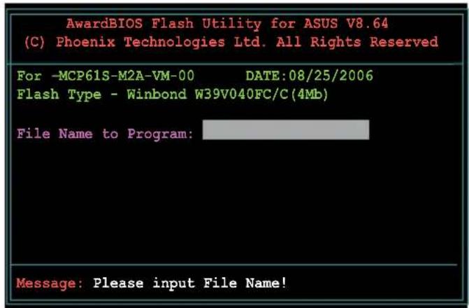
- Type the BIOS file name in the File Name to Program field, then press .

- Press when the utility prompts you to save the current BIOS file. The following screen appears.
- The utility verifies the BIOS file in the floppy disk and starts flashing the BIOS file.


Do not turn off or reset the system during the flashing process!
- The utility displays a Flashing Complete message indicating that you have successfully flashed the BIOS file. Remove the floppy disk, then press to restart the system.

5.1.44 ASUS CrashFreeBIOS 3 utility
ASUS CrashFree BIOS 3 is an auto recovery tool that allows you to restore the BIOS file when it fails or gets corrupted during the updating process. You can update a corrupted BIOS file using the motherboard support CD, the floppy disk, or the USB flash disk that contains the updated BIOS file.

Prepare the motherboard support CD or the floppy disk containing the updated motherboard BIOS before using this utility.
Recovering the BIOS from the support CD
To recover the BIOS from the support CD:
- Turn on the system.
- Insert the support CD into the optical drive.
- The utility displays the following message and automatically checks the CD for the BIOS file.
Bad BIOS checksum. Starting BIOS recovery...
Checking for floppy...
When found, the utility reads the BIOS file and starts flashing the corrupted BIOS file.
Bad BIOS checksum. Starting BIOS recovery...
Checking for floppy...
Floppy not found!
Reading file "M2A-VM.bin". Completed.
Start flashing...
- Restart the system after the utility completes the updating process.
Recovering the BIOS from a floppy/USB flash disk
To recover the BIOS from a floppy/USB flash disk:
- Download the latest BIOS from the ASUS website (www.asus.com). Rename the BIOS file to WDG2WSP.ROM.
- Insert the floppy/USB flash disk that contains the BIOS file into the FDD/USB port.
- Turn on the system.
- The utility automatically checks the devices for the BIOS file. When found, the utility reads the BIOS file and starts flashing the corrupted BIOS file.
- Restart the system after the utility completes the updating process.

- Only the USB flash disk with FAT 32/16 format and single partition can support ASUS CrashFree BIOS 3. The device size should be smaller than 8 GB.
- Flash time takes around one minute.
- DO NOT shut down or reset the system while updating the BIOS! Doing so can cause system boot failure!
5.1.55 ASUS Update utility
The ASUS Update is a utility that allows you to manage, save, and update the motherboard BIOS in Windows® environment. The ASUS Update utility allows you to:
- Save the current BIOS file
- Download the latest BIOS file from the Internet
- Update the BIOS from an updated BIOS file
- Update the BIOS directly from the Internet, and view the BIOS version information.
This utility is available in the support CD that comes with the motherboard package.

ASUS Update requires an Internet connection either through a network or an Internet Service Provider (ISP).
Installing ASUS Update
To install ASUS Update:
- Place the support CD in the optical drive. The Drivers menu appears.
- Click the Utilities tab, then click Install ASUS Update.
- The ASUS Update utility is copied to your system.

Quit all Windows® applications before you update the BIOS using this utility.
Updating the BIOS through the Internet
To update the BIOS through the Internet:
- Launch the ASUS Update utility from the Windows® desktop by clicking Start > Programs > ASUS > ASUSUpdate > ASUSUpdate. The ASUS Update main window appears.


- Select Update BIOS from the Internet option from the drop-down menu, then click Next.

- Select the ASUS FTP site nearest you to avoid network traffic, or click Auto Select. Click Next.
- From the FTP site, select the BIOS version that you wish to download. Click Next.
- Follow the screen instructions to complete the update process.

The ASUS Update utility is capable of updating itself through the Internet. Always update the utility to avail all its features.

Updating the BIOS through a BIOS file
To update the BIOS through a BIOS file:
- Launch the ASUS Update utility from the Windows® desktop by clicking Start > Programs > ASUS > ASUSUpdate > ASUSUpdate. The ASUS Update main window appears.
- Select Update BIOS from a file option from the drop-down menu, then click Next.
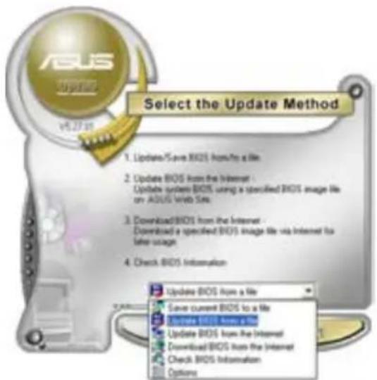
- Locate the BIOS file from the Open window, then click Open.
- Follow the screen instructions to complete the update process.

5.2 BIOS setup program
5.2.1 BIOS menu screen
![Main Advanced Power Boot Tools Exit. Phoenix-AwardBIOS CMOS Setup Utility. System Time 15:30:36. System Date Mon, Mar 2 2006. Legacy Diskette A: [1.44M, 3.5 in.]. Primary IDE Master [ST321122A]. Primary IDE Slave [ASUS CDS520/A]. SATA1 [None]. SATA2 [None]. SATA3 [None]. SATA4 [None]. HDD SMART Moni…](/content/2026/06/1344752/images/0d79c609f54b1b380ee1eecc8b741e9c93ff03522a0a5068c17f0b8392dfe4e8.jpg)
5.2.2 Menu bar
The menu bar on top of the screen has the following main items:
Main: For changing the basic system configuration
Advanced: For changing the advanced system settings
Power: For changing the advanced power management (APM) configuration
Boot: For changing the system boot configuration
Tools: For changing the system tools configuration
Exit: For selecting the exit options and loading default settings
To select an item on the menu bar, press the right or left arrow key on the keyboard until the desired item is highlighted.

- The BIOS setup screens shown in this chapter are for reference purposes only, and may not exactly match what you see on your screen.
- Visit the ASUS website (www.asus.com) to download the latest BIOS information.
5.2.3 Legend bar
At the bottom of the Setup screen is a legend bar. The keys in the legend bar allow you to navigate through the various setup menus. The following table lists the keys found in the legend bar with their corresponding functions.
| Navigation Key Function |
| Exits the BIOS setup or returns to the main menu from a sub-menu |
| Left or Right arrow Selects the menu item to the left or right |
| Up or Down arrow Moves the highlight up or down between fields |
| Page Down or - (minus) Scrolls backward through the values for the highlighted field |
| Page Up or + (plus) Scrolls forward through the values for the highlighted field |
| Brings up a selection menu for the highlighted field |
| Saves changes and exit |
5.2.4 Menu items
The highlighted item on the menu bar displays the specific items for that menu. For example, selecting Main shows the Main menu items.
The other items (Advanced, Power, Boot, and Exit) on the menu bar have their respective menu items.
5.2.5 Sub-menu items
A solid triangle before each item on any menu screen means that the item has a sub-menu. To display the sub-menu, select the item and press .
5.2.6 Configuration fields
These fields show the values for the menu items. If an item is user-configurable, you can change the value of the field opposite the item. You cannot select an item that is not user-configurable.
A configurable field is enclosed in brackets, and is highlighted when selected. To change the value of a field, select it then press to display a list of options. Refer to “2.2.7 Pop-up window.”
5.2.7 Pop-up window
Select a menu item then press to display a pop-up window with the configuration options for that item.
![Phoenix-Award BIOS CMOS Setup Utility. Main Advanced Power Boot Tools Exit. System Time 15:30:36. System Date Mon, Jan 03 2007. Legacy Diskette A: [1.44M, 3.5 in.]. Primary IDE Master. Primary IDE Slave. SATA1. SATA2. SATA3. SATA4. HDD SMART Monitor. Installed Memory. Usable Memory. Select Menu. Ite…](/content/2026/06/1344752/images/086d380d00dd59c91e4836065d6ea3d49556149b909f5512387d95023817ea5b.jpg)
5.2.8 General help
At the top right corner of the menu screen is a brief description of the selected item.
5.3 Main menu
When you enter the BIOS Setup program, the Main menu screen appears, giving you an overview of the basic system information.

Refer to section "5.2.1 BIOS menu screen" for information on the menu screen items and how to navigate through them.
![Phoenix-Award BIOS CMOS Setup Utility. Main Advanced Power Boot Tools Exit. System Time 15:30:36. System Date Mon, Mar 2 2006. Legacy Diskette A: [1.44M, 3.5 in.]. Primary IDE Master [ST321122A]. Primary IDE Slave [ASUS CDS520/A]. SATA1 [None]. SATA2 [None]. SATA3 [None]. SATA4 [None]. HDD SMART Mon…](/content/2026/06/1344752/images/e7e22da64ef6141c6daf38203212cfd9acd440e6292f17f9226949aa6a609223.jpg)
5.3.1 System Time [hh:mm:ss]
Allows you to set the system time.
5.3.2 System Date [Day mm/dd/yyyy]
Allows you to set the system date.
5.3.33 Legacy Diskette A [1.44M, 3.5 in.]
Sets the type of floppy drive installed. Configuration options: [Disabled] [720K, 3.5 in.] [1.44M, 3.5 in.]
5.3.44 Primary IDE Master/Slave
While entering Setup, the BIOS automatically detects the presence of IDE devices. There is a separate sub-menu for each IDE device. Select a device item then press to display the IDE device information.
| Phoenix-Award BIOS CMOS Setup Utility | |
| Main | |
| Primary IDE Master | Select Menu |
| Primary IDE Master [Auto] Access Mode [Auto] Capacity 82 GB Cylinder 39420 Head 16 Sector 255 PIO Mode [Auto] UDMA Mode [Auto] Transfer Mode UDMA 6 | Item Specific Help ▶ Press [Enter] to select |
| F1:Help ↑↓: Select Item -/+: Change Value F5: Setup Defaults ESC: Exit →←: Select Menu Enter: Select SubMenu F10: Save and Exit | |
The BIOS automatically detects the values opposite the dimmed items (Capacity, Cylinder, Head, Sector and Transfer Mode). These values are not user-configurable. These items show N/A if no IDE device is installed in the system.
Primary IDE Master/Slave [Auto]
Select [Auto] to automatically detect an IDE hard disk drive. If automatic detection is successful, the BIOS automatically fills in the correct values for the remaining fields on this sub-menu. If the hard disk was already formatted on a previous system, the setup BIOS may detect incorrect parameters. Select [Manual] to manually enter the IDE hard disk drive parameters. If no drive is installed select [None]. Configuration options: [None] [Auto] [Manual]
Access Mode [Auto]
The default [Auto] allows automatic detection of an IDE hard disk drive. Select [CHS] for this item if you set the Primary IDE Master/Slave to [Manual]. Configuration options: [CHS] [LBA] [Large] [Auto]
![ASUS V3-M2A690G - Access Mode [Auto] - 1](/content/2026/06/1344752/images/7632852037566a5288b5e61d00be27595d77528c7412cad1d21b208202ecc218.jpg)
Before attempting to configure a hard disk drive, make sure you have the correct configuration information supplied by the drive manufacturer. Incorrect settings may cause the system to fail to recognize the installed hard disk.
Capacity
Displays the auto-detected hard disk capacity. This item is not configurable.
Cylinder
Shows the number of the hard disk cylinders. This item is not configurable.
Head
Shows the number of the hard disk read/write heads. This item is not configurable.
Sector
Shows the number of sectors per track. This item is not configurable.
PIO Model [Auto]:
Sets the PIO mode for the IDE device.
Configuration options: [Auto] [Mode 0] [Mode 1] [Mode 2] [Mode 3] [Mode 4]
UDMA Model [Auto]
Disables or sets the UDMA mode. Configuration options: [Disabled] [Auto]
Transfer Mode
Shows the Transfer mode. This item is not configurable.

After entering the IDE hard disk drive information into BIOS, use a disk utility, such as FDISK, to partition and format new IDE hard disk drives. This is necessary so that you can write or read data from the hard disk. Make sure to set the partition of the Primary IDE hard disk drives to active.
5.3.55 SATAT1A41-4
While entering Setup, the BIOS automatically detects the presence of Serial ATA devices. There is a separate sub-menu for each SATA device. Select a device item then press to display the SATA device information.
| Main | |
| SATA 1 | Select Menu |
| Extended IDE Drive [Auto] Access Mode [Auto] Capacity 0 MB Cylinder 0 Head 0 Landing Zone 0 Sector 0 | Item Specific Help ▶ Slects the type of fixed disk connected to the system. |
| F1:Help ↑↓: Select Item -/+ : Change Value F5: Setup Defaults ESC: Exit →←: Select Menu Enter: Select SubMenu F10: Save and Exit | |
The BIOS automatically detects the values opposite the dimmed items (Capacity, Cylinder, Head, Precomp, Landing Zone and Sector). These values are not user-configurable. These items show 0 if no SATA device is installed in the system.
Extended Drive [Auto]
Selects the type of fixed disk connected to the system.
Configuration options: [None] [Auto]
Access Mode [Auto]
Sets the sector addressing mode. Configuration options: [Large] [Auto]
![ASUS V3-M2A690G - Access Mode [Auto] - 1](/content/2026/06/1344752/images/6b133eac9469270f3e04f3e160311393ec7ac606750099860c1bcc3691426a12.jpg)
Before attempting to configure a hard disk drive, make sure you have the correct configuration information supplied by the drive manufacturer. Incorrect settings may cause the system to fail to recognize the installed hard disk.
Capacity
Displays the auto-detected hard disk capacity. This item is not configurable.
Cylinder
Shows the number of the hard disk cylinders. This item is not configurable.
Head
Shows the number of the hard disk read/write heads. This item is not configurable.
Landing Zone
Shows the number of landing zone per track. This item is not configurable.
Sector
Shows the number of sectors per track. This item is not configurable.

After entering the IDE hard disk drive information into BIOS, use a disk utility, such as FDISK, to partition and format new IDE hard disk drives. This is necessary so that you can write or read data from the hard disk. Make sure to set the partition of the Primary IDE hard disk drives to active.
5.3.66 HDD SMART Monitoring [Disabled]
Allows you to enable or disable the HDD Self-Monitoring Analysis and Reporting Technology (SMART) feature.
Configuration options: [Disabled] [Enabled]
5.3.77 Installed Memory [xx MB]
Shows the size of installed memory.
5.3.88 Usable Memory [XXX MB]
Shows the size of usable memory.
5.4 Advanced menu
The Advanced menu items allow you to change the settings for the CPU and other system devices.

Take caution when changing the settings of the Advanced menu items. Incorrect field values can cause the system to malfunction.

5.4.11 JumperFree Configuration
![Phoenix-Award BIOS CMOS Setup Utility Advanced JumperFree Configuration +1.2VNBSB [Auto] DDR2 Voltage Control [Auto] CPU Voltage Control [Auto] CPU Multiplier [Auto] CPU Voltage [Auto] CPU Frequency [200MHz]](/content/2026/06/1344752/images/22ce5052c2c8cfbfd70c141bd4d825294d5b8a798f1200a133b962113860a173.jpg)
+1.2V NBSB [Auto]
Allows you to set the +1.2V NBSB voltage.
Configuration options: [Auto] [+1.20V] [+1.30V] [+1.40V] [+1.50V]
DDR2 Voltage Control [Auto]
Allows you to set the operating DDR2 voltage.
Configuration options: [Auto] [+1.80V] [+1.90V] [+2.00V] [+2.10V]
CPU Voltage Control [Auto]
Allows you to set the operating CPU voltage.
Configuration options: [Auto] [100mV]
CPU Multiplier [Auto]
Allows you to set the operating CPU multiplier.
Configuration options: [Auto] [5x] [6x] [7x] [8x] [9x]
CPU Voltage [Auto]
Allows you to set the operating voltage.
Configuration options: [Auto] [1.400v] [1.375v] [1.350v] [1.325v]
[1.300v]...[0.800v]
CPU Frequency [20MHz] Hz
Allows you to adjust the CPU frequency. Use the numeric keys to type in the desired CPU frequency. The values range from 200 to 400.
5.4.22 CPU Configuration
![Phoenix-Award BIOS CMOS Setup Utility Advanced CPU Configuration CPU Type AMD Sempron(tm) Processor 3400+ CPU Speed 1800MHz Cache RAM 256K AMD Live! [Disabled] AMD Cool'n'Quiet Function [Auto]](/content/2026/06/1344752/images/f397387ec9f6252be64f196e7cbc3b11e8461452690e553cf1b3c6395fb83300.jpg)
AMD Live! [Disabled]
Enables or disables the AMD Live! technology.
Configuration options: [Disabled] [Enabled]
AMD Cool 'n' Quiet Function [Disabled]
Enables or disables the AMD Cool 'n' Quiet technology.
Configuration options: [Auto] [Disabled]
5.4.33 Chipset
| Chipset | Select Menu |
| DRAM Configuration LDT & PCI Bus Control UMA Frame Buffer Size [64MB] Current UMA Size 64 MB X Surroundview Disabled Spread Spectrum [Autoz] | Item Specific Help ▶ DRAM timing and control |
DRAM Configuration
| Phoenix-Award BIOS CMOS Setup Utility | |
| Advanced | |
| DRAM Configuration | Select Menu |
| Timing Mode [Auto] | Item Specific Help >> |
| x Memory Clock Frequency Auto | Control DDR2 Voltage by software |
Timing Mode [Auto]
Configuration options: [Auto] [Manual]

The following item becomes user-configurable when the Timing Mode item is set to [Manual].
Memory Clock Frequency [Auto]
Allows you to adjust the memory clock frequency.
Configuration options: [Auto] [DDR2 533] [DDR2 667] [DDR2 800]
LDT & PCI Bus Control
| Phoenix-Award BIOS CMOS Setup Utility | |
| Advanced | |
| LDT & PCI Bus Control | Select Menu |
| LDT Bus Frequency [Auto] | Item Specific Help ▶▶▶ |
LDT Bus Frequency [Auto]
Allows you to adjust the LDT Bus frequency.
Configuration options: [Auto] [1GHz] [800MHz] [600MHz] [400MHz] [200MHz]
UMA Frame Buffer Size [64MB]
Configuration options: [32MB] [64MB] [128MB] [256MB]
Surround View [Disabled]
Allows you to disable or enable the Surround View function.
Configuration options: [Disabled] [Enabled]
![ASUS V3-M2A690G - Surround View [Disabled] - 1](/content/2026/06/1344752/images/301b76e9bb114ca29add20f02ea314460a2b615c7f8e0bdd38bb0f3ed86a4d2b.jpg)
This item becomes user-configurable when you install an ATI graphics card into the PCI Express x16 slot.
Spread Spectrum [Auto]
Allows you to disable or set to Auto the clock generator spread spectrum.
Configuration options: [Disabled] [Auto]
5.4.44 PnP/PCI
| Phoenix-Award BIOS CMOS Setup Utility Advanced | |
| PCIPnP | Select Menu |
| Plug & Play O/S [No] Resources Controlled By [Auto] x IRQ Resources PCI Latency Timer(CLK) [64] ** PCI Express relative items ** Maximum Payload Size [4096] | Item Specific Help ▶ Select Yes if you are using a Plug and Play capable operating system Select No if you need the BIOS to configure non-boot devices |
Plug & Play O/S [No]
When set to [No], the BIOS configures all the devices in the system.
When set to [Yes] and if you install a Plug and Play operating system, the operating system configures the Plug and Play devices not required for boot. Configuration options: [No] [Yes]
Resources Controlled By [Auto]
When set to [Auto], the BIOS automatically configures all the boot and Plug and Play compatible devices. Set to [Manual] if you want to assign the IRQ DMA and memory base address fields.
Configuration options: [Auto] [Manual]
![ASUS V3-M2A690G - Resources Controlled By [Auto] - 1](/content/2026/06/1344752/images/211d3578da32da6b934a67d30ce1882295c3e46df7ac523ec1c69774220b48bf.jpg)
When the item Resources Controlled By is set to [Auto], the item IRQ Resources is grayed out and not user-configurable. Refer to the section "IRQ Resources" for information on how to enable this item.
IRQ Resources
This sub-menu is activated only when the Resources Controlled By item is set to [Manual].
| Phoenix-Award BIOS CMOS Setup Utility Advanced | |
| IRQ Resources | Select Menu |
| IRQ-3 assigned to [PCI Device] | Item Specific Help >> |
| IRQ-4 assigned to [PCI Device] | |
| IRQ-5 assigned to [PCI Device] | Legacy ISA for devices |
| IRQ-7 assigned to [PCI Device] | compliant with the |
| IRQ-10 assigned to [PCI Device] | original PC AT bus |
| IRQ-11 assigned to [PCI Device] | specification, PCI/ISA PnP |
| IRQ-14 assigned to [PCI Device] | for devices compliant with |
| IRQ-15 assigned to [PCI Device] | |
IRQ Resources
When set to [PCI Device], the specific IRQ is free for use of PCI/PnP devices. When set to [Reserved], the IRQ is reserved for legacy ISA devices. Configuration options: [PCI Device] [Reserved]
PCI Latency Timer (CLK) [64]
Use <+> and <-> to adjust the value. The value ranges from 0 to 255.
Maximum Payload Size [4096]
Sets maximum TLP payload size for the PCI Express devices. The unit is byte. Configuration options: [128] [256] [512] [1024] [2048] [4096]
5.4.55 Onboard Device Configuration
| Phoenix-Award BIOS CMOS Setup Utility Advanced | |
| Onboard Device Configuration | Select Menu |
| South OnChip IDE Device South OnChip PCI Device Front Panel Type [HD Audio] Primary Display Adapter [PCIEx] Onboard LAN [Enabled] Onboard LAN Boot ROM [Disabled] Serial Port1 Address [3F8/IRQ4] Parallel Port Address [378/IRQ7] Parallel Port Mode [EPP] x: ECP Mode Use DMA 3 | Item Specific Help ▶ |
| F1:Help ↑↓: Select Item -/+ : Change Value F5: Setup Defaults ESC: Exit →←: Select Menu Enter: Select SubMenu F10: Save and Exit | |
South OnChip ID Device
| Phoenix-Award BIOS CMOS Setup Utility | |
| Advanced | |
| South OnChip IDE Device | Select Menu |
| IDE DMA transfer access [Enabled]OnChip IDE Channel0 [Enabled]IDE Prefetch Mode [Disabled] | Item Specific Help ▶ |
IDE DMA transfer access [Enabled]
Allows you to enable or disable the IDE DMA transfer access.
Configuration options: [Disabled] [Enabled]
OnChip IDE Channel 0 [Enabled]
Allows you to enable or disable the onchip IDE channel 0 controller.
Configuration options: [Disabled] [Enabled]
IDE Prefetch Mode [Disabled]
Allows you to enable or disable the IDE PIO read prefetch mode.
Configuration options: [Disabled] [Enabled]
South OnChip PC Device
| Phoenix-Award BIOS CMOS Setup Utility | |
| Advanced | |
| South OnChip PCI Device | Select Menu |
| Onboard SATA Controller [Enabled]Onboard SATA Type [RAID Controller] | Item Specific Help ▶ |
Onboard SATA Controller [Enabled]
Allows you to enable or disable the onboard Serial ATA controller.
Configuration options: [Disabled] [Enabled]
Onboard SATA Type [IDE Controller]
Allows you to select the onboard Serial ATA type.
Configuration options: [IDE Controller] [RAID Controller] [AHCI
Controller]
Front Panel Type [HD Audio]
Allows you to set the front panel audio connector (AAFP) mode to legacy AC'97 or high-definition audio depending on the audio standard that the front panel audio module supports. Configuration options: [AC97] [HD Audio]
Primary Display Adapter [PCIEx]
Sets which graphics controller to use as primary boot device.
Configuration options: [PCI Slot] [OnChipVGA] [PCIEx]
Onboard LAN [Enabled]
Allows you to enable or disable the onboard LAN device support.
Configuration options: [Disabled] [Enabled]
OnBoard LAN Boot ROM [Disabled]
Allows you to enable or disable the onboard LAN boot ROM.
Configuration options: [Disabled] [Enabled]
Serial Port1 Address [3F8/IRQ4]
Allows you to select the Serial Port1 base address.
Configuration options: [Disabled] [3F8/IRQ4] [2F8/IRQ3] [3E8/IRQ4]
[2E8/IRQ3] [Auto]
Parallel Port Address [378/IRQ7]
Allows you to select the Parallel Port address.
Configuration options: [Disabled] [378/IRQ7] [278/IRQ5] [3BC/IRQ7]
Parallel Port Mode [EPP]
Allows you to select the Parallel Port mode.
Configuration options: [Normal] [EPP] [ECP] [Bi-Directional]
![ASUS V3-M2A690G - Parallel Port Mode [EPP] - 1](/content/2026/06/1344752/images/5390f8f051d365d1b4ef8e347928644875aac81108c64a8f58b1a0bafa143dc9.jpg)
The “ECP Mode Use DMA” item becomes user-configurable when the Parallel Port Mode item is set to [ECP] or [Bi-Directional]
ECP Mode Use DMA [3]
Allows selection of ECP Mode. Configuration options: [1] [3]
5.4.66 USB Configuration
The items in this menu allows you to change the USB-related features. Select an item then press to display the configuration options
| Phoenix-Award BIOS CMOS Setup Utility Advanced | |
| USB Configuration | Select Menu |
| USB Controller [Enabled] USB EHCI Controller [Enabled] USB Legacy support [Enabled] | Item Specific Help ▶ |
USB Controller [Enabled]
Allows you to enable or disable the USB controller.
Configuration options: [Disabled] [Enabled]
USB EHC Controller I [Enabled]
Allows you to enable or disable the onchip USB controller.
Configuration options: [Disabled] [Enabled]
USB Legacy Support [Enabled]
Allows you to enable or disable support for USB devices on legacy operating systems (OS). Configuration options: [Disabled] [Enabled]
5.5 Power menu
The Power menu items allow you to change the settings for the Advanced Configuration and Power Interface (ACPI) and the Advanced Power Management (APM). Select an item then press to display the configuration options.
| Phoenix-Award BIOS CMOS Setup Utility | |||
| Main Advanced Power Boot Tools Exit | |||
| ACPI Suspend Type [S1&S3] ACPI APIC support [Enabled] APM Configuration Hardware Monitor | Select Menu | ||
| Item Specific Help Select the ACPI state used for System Suspend. | |||
| F1:Help ↑↓: Select Item -/+ : Change Value F5: Setup Defaults ESC: Exit →←: Select Menu Enter: Select SubMenu F10: Save and Exit | |||
5.5.11 ACPI Suspend Type [S1&S3]
Allows you to select the Advanced Configuration and Power Interface (ACPI) state to be used for system suspend.
Configuration options: [S1 (POS)] [S3(STR)] [S1&S3]
5.5.22 ACPI APIC Support [Enabled]
Allows you to enable or disable the Advanced Configuration and Power Interface (ACPI) support in the Application-Specific Integrated Circuit (ASIC). When set to Enabled, the ACPI APIC table pointer is included in the RSDT pointer list. Configuration options: [Disabled] [Enabled]
5.5.33 APM Configuration
| Phoenix-Award BIOS CMOS Setup Utility | |
| Power | |
| APM Configuration | Select Menu |
| Power On By External Modems [Disabled] Restore on AC Power Loss [Power-Off] PWR Button < 4 secs [Instant-Off] Power Up On PCI/PCIE Devices [Disabled] HPET support [Enabled] Power Up By PS/2 Mouse [Disabled] Power Up By PS/2 Keyboard [Disabled] Power On by RTC Alarm [Disabled] x Date (of Month) Alarm 0 x Alarm Time (hh:mm) 0:0:0 | Item Specific Help |
| F1:Help ↑↓: Select Item -/+ : Change Value F5: Setup Defaults ESC: Exit →←: Select Menu Enter: Select SubMenu F10: Save and Exit | |
Power On By External Modem [Disabled]
This allows either settings of [Enabled] or [Disabled] for powering up the computer when the external modem receives a call while the computer is in Soft-off mode. Configuration options: [Disabled] [Enabled]
![ASUS V3-M2A690G - Power On By External Modem [Disabled] - 1](/content/2026/06/1344752/images/42718b3d16cfd14c6c8ed65a399bf872354a52ed6c3291a1b632cb72d9d7f26b.jpg)
The computer cannot receive or transmit data until the computer and applications are fully running. Thus, connection cannot be made on the first try. Turning an external modem off and then back on while the computer is off causes an initialization string that turns the system power on.
Restore on AC Power Loss [Power Off]
When set to Power Off, the system goes into off state after an AC power loss. When set to Power On, the system goes on after an AC power loss. When set to
Configuration options: [Power Off] [Power On]
PWR Button < 4 secs [Instant-Off]
Allows you to set the event after the power button is pressed for more than 4 seconds. Configuration options: [Suspend] [Instant-Off]
PowerUp On PCI/PCIE Devices [Disabled]
Allows you to enable or disable the PME to wake up from S5 by PCI/PCIE devices & NV Onboard LAN. Configuration options: [Disabled] [Enabled]
HPET Support [Enabled]
Configuration options: [Enabled] [Disabled]
Power On By PS/2 Mouse [Disabled]
When set to [Enabled], this parameter allows you to use the PS/2 mouse to turn on the system. This feature requires an ATX power supply that provides at least 1A on the +5VSB lead.
Configuration options: [Disabled] [Enabled]
PowerOn ByPS72 Keyboard[Disabled]
Allows you to disable the Power On by PS/2 keyboard function or set specific keys on the PS/2 keyboard to turn on the system. This feature requires an ATX power supply that provides at least 1A on the +5VSB lead.
Configuration options: [Disabled] [Space Bar] [Ctrl-ESC] [Power Key]
PowerOnByRTCTAlarma[Disabled]
Allows you to enable or disable RTC to generate a wake event. When this item is set to Enabled, the items Date of Month Alarm and Time (hh:mm:ss) Alarm items become user-configurable with set values.
Configuration options: [Disabled] [Enabled]
Date of Month Alarm [xx]
To set the date of alarm, highlight this item and press to display the Date of Month Alarm pop-up menu. Key-in a value within the specified range then press . Configuration options: [Min=0] [Max=31]
Alarm Time (hh:mm) [xx:xx:xx]
To set the time of alarm:
- Highlight this item and press to display a pop-up menu for the hour field.
- Key-in a value (Min=0, Max=23), then press .
- Press to move to the minutes field then press .
- Key-in a minute value (Min=0, Max=59), then press .
- Press to move to the seconds field then press .
- Key in a value (Min=0, Max=59), then press .
5.5.44 Hardware Monitor
The items in this sub-menu display the hardware monitor values automatically detected by the BIOS. It also allows you to change CPU Q-Fan feature-related parameters. Select an item then press to display the configuration options.
| Hardware Monitor | Select Menu |
| Q-Fan Controller [Enabled] CPU Fan Type [DC] Vcore Voltage [1.56V] 3.3V Voltage [3.18V] 5V Voltage [5.05V] 12V Voltage [11.58V] | Item Specific Help ▶ Press [Enter] to enable or disable |
| CPU Temperature 48°C MB Temperature 41°C CPU FAN Speed 3068 RPM CHA FAN Speed 0 RPM PWR FAN Speed 0 RPM CPU Fan Speed warning [800 RPM] HPET Support [Enabled] |
Q-Fan Controller [Disabled]
Allows you to enable or disable the Q-Fan controller.
Configuration options: [Disabled] [Enabled]
CPU Fan Type [DC]
Allows you to select the CPU fan type.
Configuration options: [DC] [PWM]
Vcore Voltage, 3.3V Voltage, 5V Voltage, 12V Voltage
The onboard hardware monitor automatically detects the voltage output through the onboard voltage regulators.
Configuration options: [xxx] [Ignored]
CPU Temperature, MB Temperature
The onboard hardware monitor automatically detects and displays the motherboard and CPU temperatures. These items are not user-configurable.
CPU Fan Speed [xxxRPM]
CHA_FAN Speed [xxxxRPM]
PWR_FAN Speed [xxxxRPM]
The onboard hardware monitor automatically detects and displays the CPU, chassis, and chip fan speeds in rotations per minute (RPM). If any of the fans is not connected to the motherboard, the field shows 0. These items are not user-configurable.
CPU Fan Speed Warning [800 RPM]
Sets the CPU fan speed warning feature.
Configuration options: [Disabled] [800RPM] [1200RPM] [1600RPM]
5.6 Boot menu
The Boot menu items allow you to change the system boot options. Select an item then press <Enter> to display the sub-menu.
| Phoenix-Award BIOS CMOS Setup Utility | |
| Main Advanced Power Boot Tools Exit | |
| Boot Device Priority Removable Drives Hard Disk Drives Boot Settings Configuration Security | Select Menu |
| Item Specific Help Press [Enter] to Set. | |
| F1:Help ↑↓: Select Item -/+: Change Value F5: Setup Defaults ESC: Exit →←: Select Menu Enter: Select SubMenu F10: Save and Exit | |
5.6.1 Boot Device Priority
| Phoenix-Award BIOS CMOS Setup Utility | |
| Power | |
| Boot Device Priority | Select Menu |
| 1st Boot Device [Removable] | Item Specific Help ▶ |
| 2nd Boot Device [Hard Disk] | Select Your Boot |
| 3rd Boot Device [CDROM] | Device Priority |
| 4th Boot Device [Disabled] | |
1st ~ 4th Boot Device [Removable]
These items specify the boot device priority sequence from the available devices. The number of device items that appears on the screen depends on the number of devices installed in the system.
Configuration options: [Removable] [Hard Disk] [CDROM] [Disabled]
5.6.2 Removable Drives

1. Floppy Disks
Allows you to assign a removable drive attached to the system.
5.6.33 Hard Disk Drives

1. SATA
Allows you to assign a hard disk drive attached to the system.
5.6.44 Boot Settings Configuration
| Phoenix-Award BIOS CMOS Setup Utility Boot | |
| Boot Settings Configuration | Select Menu |
| Case Open Warning [Enabled] Quick Boot [Enabled] Boot Up Floppy Seek [Disabled] Bootup Num-Lock [On] Typematic Rate Setting [Disabled] x Typematic Rate (Chars/Sec) 6 x Typematic Delay (Msec) 250 OS Select For DRAM > 64MB [Non-OS2] Full Screen LOGO [Enabled] Halt On [All, But keyboard] | Item Specific Help ▶▶ Press [Enter] to enable or disable. |
| F1:Help ↑↓: Select Item -/+ : Change Value F5: Setup Defaults ESC: Exit ←: Select Menu Enter: Select SubMenu F10: Save and Exit | |
Case Open Warning [Enabled]
Enables or disables the chassis open status feature. Setting to Enabled clears the chassis open status. Refer to section "1.10.2 Internal connectors" for setting details. Configuration options: [Disabled] [Enabled]
Quick Boot [Enabled]
Allows you to enable or disable the system quick boot feature. When Enabled, the system skips certain tests while booting. Configuration options: [Disabled] [Enabled]
Boot Up Floppy Seek [Disabled]
Enables or disables the chassis open status feature. Setting to Enabled clears the chassis open status. Configuration options: [Disabled] [Enabled]
Bootup NumLock [On]
Allows you to select the power-on state for the NumLock.
Configuration options: [Off] [On]
Typematic Rate Setting [Disabled]
Allows you to set the keystroke rate. Enable this item to configure the Typematic Rate (Chars/Sec) and the Typematic Delay (Msec).
Configuration options: [Disabled] [Enabled]
![ASUS V3-M2A690G - Typematic Rate Setting [Disabled] - 1](/content/2026/06/1344752/images/73c1db8484499a6c7cba0fb9b4ccbb2e38966f58a14c9beb238c35229fa449f0.jpg)
The items Typematic Rate (Chars/Sec) and Typematic Delay (Msec) become user-configurable only when the item Typematic Rate Setting is enabled.
Typematic Rate (Chars/Sec) [6]
Allows you to select the rate at which a character repeats when you hold a key. Configuration options: [6] [8] [10] [12] [15] [20] [24] [30]
Typematic Delay (Msec) [250]
Allows you to set the delay before keystrokes begin to repeat.
Configuration options: [250] [500] [750] [1000]
OS Select for DRAM>64MB [Non-OS2]-OS2]
Set this item to OS2 only when you are running on an OS/2 operating system with an installed RAM of greater than 64 KB.
Configuration options: [Non-OS2] [OS2]
FullIScreenLOGO [Enabled]
Allows you to enable or disable the full screen logo display feature.
Configuration options: [Disabled] [Enabled]
![ASUS V3-M2A690G - FullIScreenLOGO [Enabled] - 1](/content/2026/06/1344752/images/c687d248d9685f87af6e480f6eb8aaf9d88a3f52a2da103f8670cf30ff2ef813.jpg)
Make sure that the above item is set to [Enabled] if you want to use the ASUS MyLogo2™ feature.
HaltOnr[A][A, But Keyboard]ard]
Allows you to set the error report type.
Configuration options: [All Errors] [No Errors] [All, But Keyboard] [All, But Diskette] [All, But Disk/Key]
5.6.55 Security
| Phoenix-Award BIOS CMOS Setup Utility | |
| Boot | |
| Security | Select Menu |
| Supervisor Password ClearUser Password ClearPassword Check [Setup] | Item Specific Help ▶ |
Supervisor Password User Password
These fields allow you to set passwords:
To set a password:
- Select an item then press <Enter>.
- Type in a password using a combination of a maximum of eight (8) alpha-numeric characters, then press <Enter>.
- When prompted, confirm the password by typing the exact characters again, then press <Enter>. The password field setting is changed to Set.
To clear the password:
- Select the password field and press <Enter> twice. The following message appears:

- Press any key to continue. The password field setting is changed to Clear.
A note about passwords
The Supervisor password is required to enter the BIOS Setup program preventing unauthorized access. The User password is required to boot the system preventing unauthorized use.
Forgot your password?
If you forget your password, you can clear it by erasing the CMOS Real Time Clock (RTC) RAM. The RAM data containing the password information is powered by the onboard button cell battery. If you need to erase the CMOS RAM, refer to section "1.9 Jumpers" for instructions.
Password Check
This field requires you to enter the password before entering the BIOS setup or the system. Select [Setup] to require the password before entering the BIOS Setup. Select [System] to require the password before entering the system. Configuration options: [Setup] [System]
5.7 Tools menu
The Tools menu items allow you to configure options for special functions. Select an item then press to display the sub-menu.
![Phoenix-Award BIOS CMOS Setup Utility Main Advanced Power Boot Tools Exit ▶ ASUS Music Alarm ▶ ASUS O.C. Profile ▶ EZ Flash 2 Select Menu Item Specific Help ▶ Press [Enter] to Set. F1:Help ↑↓: Select Item -/+: Change Value F5: Setup Defaults ESC: Exit →←: Select Menu Enter: Select SubMenu F10: Save…](/content/2026/06/1344752/images/2e779a3fed405ad1a2586a0220ebf43c0f546cf8bced7329577eaeb5d0d48d03.jpg)
5.7.11 ASUS Music Alarm
| Phoenix-Award BIOS CMOS Setup Utility Tools | ||
| ASUS Music Alarm | Select Menu | |
| ASUS Music Alarm [Disabled] x Alarm Date: Sunday Enabled x Monday Enabled x Tuesday Enabled x Wednesday Enabled x Thursday Enabled x Friday Enabled x Saturday Enabled x Alarm Time (hh:mm) 0 : 0 x Audio CD Drive Primary IDE Master x Detect CD Enter x Starting Track N/A x Repeat Track Disabled x Length 10 Mins x Volume 16 | Item Specific Help▶ Press [Enter] to select. | |
| F1:Help ↑↓: Select Item -/+: Change Value F5: Setup Defaults ESC: Exit →←: Select Menu Enter: Select SubMenu F10: Save and Exit | ||
ASUS Music Alarm [Disabled]
Allows you to enable or disable the ASUS Music Alarm function. Configuration options: [Disabled] [Enabled]
![ASUS V3-M2A690G - ASUS Music Alarm [Disabled] - 1](/content/2026/06/1344752/images/e532bb82d310cae124c752f39d52e7e32cdbfa4f643b076ab49c612a75db97ac.jpg)
The succeeding items become user-configurable when you enable the ASUS Music Alarm.
Alarm Date: Sunday/Monday/Tuesday/Wednesday/Thursday/Friday/Saturday [Enabled]
Allows you to enable or disable the alarm for a particular day. Configuration options: [Disabled] [Enabled]
Alarm Time (hh:mm): 0:0
Allows you to set the alarm time. Press to select the field, then use <+> or <-> to change the value. The value for hour: 0~23; the value for minute: 0~59.
Audio CD Drive [Primary IDE Master]
Allows you to select the connection configuration of the optical storage device from which the alarm music will play from.
Configuration options: [Primary IDE Master] [Primary IDE Slave]
Detect CD [Enter]
Press to search the CD track number.
Starting Track
Allows you to choose the starting track from the CD from which you would like the alarm music to play.
Repeat Track [Disabled]
Allows you to enable or disable the repeat track function. Configuration options: [Disabled] [Single] [All]
Length [0 Mins]
Allows you to set the length of the music alarm. Configuration options: [10 Mins] [20 Mins] [30 Mins] [1 Hour]
Volume [16]
Allows you to set the volume level of the music alarm. Configuration options: [01] ~ [32]
![ASUS V3-M2A690G - Volume [16] - 1](/content/2026/06/1344752/images/2b214975d604a337f45b3c3594693b0d98fb8f17ab5a0e6e4eee6734b59a6533.jpg)
- Only the IDE ATAPI devices from Southbridge can support this function.
- The system needs standby power, so ensure that the power cord is plugged. • ASUS Music Alarm only supports audio CDs.
5.7.22 ASUS Profile

Load BIOS Profile

Load from Profile 1/1/2/2
Allows you to load the previous BIOS settings saved in the BIOS Flash. Press to load the file.
Load from File
Allows you to load the previous BIOS files saved in the hard disk/floppy disk/USB flash disk with the FAT32/16/12 format. Follow the instructions below to load the BIOS file.
- Insert the storage devices that contain the "xxx.CMO" file.
- Turn on the system.
- Enter BIOS setup program. Go to the "Tools" menu to select "Load from File". Press then the setup screen will appear.
- Press to switch between drives before the correct "xxx.CMO" file is found. Then press to load the file.
- A pop-up message will inform you when the loading process finishes.

- Suggest only to update the BIOS file coming from the same memory/CPU configuration and BIOS version.
- Only the "xxx.CMO" file can be loaded.
Save BIOS Profile file

Save to Profile 1/1/2/2
Allows you to save the current BIOS file to the BIOS Flash. Press to save the file.
Save to File
Allows you to save the current BIOS file to the hard disk, floppy disk, or USB flash disk with the FAT32/16/12 format. Follow the instructions below to save the BIOS file.
- Insert the storage device with enough space.
- Turn on the system.
- Enter the BIOS setup program. Go to the "Tools" menu and select "Save to File". Press <Enter> then the setup screen will appear.
- Press <Tab> to switch between drives. Press the hot-key to save the file.
- Key in the file name. Then press <Enter>.
- A pop-up message will inform you when the loading process finishes.
![ASUSTek O.C. Profile Utility B318 Current CMOS Update CMOS BOARD: M2A-VM VER: 0104 DATE: 12/12/2006 BOARD: Unknown VER: Unknown DATE: Unknown PATH: A CMOS backup is done! Press any key to Exit. DOCUME'1 PROGRA'1 SYSTEM'1 M2AVM Note [Enter] Select [Y] Yes [N/Esc] No [Left/Right]: Switch](/content/2026/06/1344752/images/bf5210eb10c32c39299a94d875c9feead49f62dc9c3fc35bd14a2f7a01538919.jpg)

The BIOS file will be saved as "xxx.CMO".
5.7.33 ASUS EZ Flash 2
Allows you to run ASUS EZ Flash 2. When you press <Enter>, a confirmation message appears. Use the left/right arrow key to select between [Yes] or [No], then press <Enter> to confirm your choice. Please see page 2-6, section 2.1.3 for details.
![ASUSTek EZ Flash 2 BIOS RROM Utility B318 FLASH TYPE: Winbond W39V080A 8Mb LPC Current ROM Update ROM BOARD: M2A-VM VER: 0104 DATE: 12/12/2006 BOARD: Unknown VER: Unknown DATE: Unknown PATH: C:\M2NPVOC A: E: WIN98SE NETTERM DRIVERS RECYCLED WUTEMP NEWFOL~1 INSTALL Note [Enter] Select [S] Save [ESC]E…](/content/2026/06/1344752/images/76cb8591ff5966aa783ac45492585c8e9713c27bc7cf3d66fd9221834cf04f23.jpg)
5.8 Exit menu
The Exit menu items allow you to load the optimal or failsafe default values for the BIOS items, and save or discard your changes to the BIOS items.


Pressing <Esc> does not immediately exit this menu. Select one of the options from this menu or from the legend bar to exit.
Exit & Save Changes
Once you are finished making your selections, choose this option from the Exit menu to ensure the values you selected are saved to the CMOS RAM. An onboard backup battery sustains the CMOS RAM so it stays on even when the PC is turned off. When you select this option, a confirmation window appears. Select YES to save changes and exit.

If you attempt to exit the Setup program without saving your changes, the program prompts you with a message asking if you want to save your changes before exiting. Press to save the changes while exiting.
Exit & Discard Changes
Select this option only if you do not want to save the changes that you made to the Setup program. If you made changes to fields other than System Date, System Time, and Password, the BIOS asks for a confirmation before exiting.
Load Setup Defaults
This option allows you to load the default values for each of the parameters on the Setup menus. When you select this option or if you press , a confirmation window appears. Select YES to load default values. Select Exit & Save Changes or make other changes before saving the values to the non-volatile RAM.
Discard Changes
This option allows you to discard the selections you made and restore the previously saved values. After selecting this option, a confirmation appears. Select YES to discard any changes and load the previously saved values.


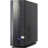
- COPYRIGHT © 2007 ASUSTEK COMPUTER INC. ALL RIGHTS RESERVED
- TABLE OF CONTENTS
- CHAPTER 1: SYSTEM INTRODUCTION
- CHAPTER 2: BASIC INSTALLATION
- CHAPTER 3: STARTING UP
- CHAPTER 4: MOTHERBOARD INFO
- CHAPTER 5: BIOS INFORMATION
- MAIN MENU
- ADVANCED MENU
- POWER MENU
- BOOT MENU
- TOOLS MENU
- EXIT MENU
- NOTICES
- FEDERAL COMMUNICATIONS COMMISSION STATEMENT
- CANADIAN DEPARTMENT OF COMMUNICATION STATEMENT
- SAFETY INFORMATION
- ELECTRICAL SAFETY
- OPERATION SAFETY
- LITHIUM-ION BATTERY WARNING
- ABOUT THIS GUIDE
- AUDIENCE
- HOW THIS GUIDE IS ORGANIZED
- CHAPTER 1: SYSTEMS INTRODUCTION
- CHAPTER 4: MOTHERBOARD INFORMATION
- CONVENTIONS USED IN THIS GUIDE
- WHERE TO FIND MORE INFORMATION
- ASUS WEBSITES
- OPTIONAL DOCUMENTATION
- SYSTEM PACKAGE CONTENTS
- ITEM DESCRIPTION
- CHAPTER
- SYSTEM INTEGRATION
- WELCOME
- FRONT PANEL
- REAR PANEL
- HDMI CARD PORTS
- VOLTAGE SELECTOR
- INTERNAL COMPONENTS
- BASIC INSTALLATION
- PREPARATION
- BASIC COMPONENTS TO INSTALL
- TOOL
- BEFORE YOU PROCEED
- REMOVING THE SIDE COVER AND FRONT PANEL ASSEMBLY
- CENTRAL PROCESSING UNIT (CPU)
- INSTALLING THE CPU
- INSTALLING THE HEATSINK AND FAN
- INSTALLING A DIMM
- MEMORY CONFIGURATIONS
- QUALIFIED VENDORS LIST (QVL)
- DDR
- DIMM SUPPORT
- INSTALLING A DDR2 DIMM
- REMOVING A DDR2 DIMM
- EXPANSION SLOTS
- INSTALLING AN EXPANSION CARD
- CONFIGURING EXPANSION CARD
- STANDARD INTERRUPT ASSIGNMENTS
- PCI EXPRESS X1 SLOT
- PCI SLOTS
- PCI EXPRESS X16 SLOT
- INSTALLING AN OPTICAL DRIVE
- INSTALLING A HARD DISK DRIVE
- INSTALLING THE CARD READER
- INSTALLING A FLOPPY DISK DRIVE
- RE-CONNECTING CABLES
- LED CABLES
- REINSTALLING THE COVER
- STARTING UP
- INSTALLING AN OPERATING SYSTEM
- POWERING UP
- SUPPORT CD INFORMATION
- RUNNING THE SUPPORT CD
- UTILITIES MENU
- ASUS INSTALL INSTALLATION WIZARD FOR UTILITIES
- ASUS COOL 'N' QUIET UTILITY
- ASUS UPDATE
- ASUS PC PROBE II
- ASUS MUSIC ALARM
- ATI WEBBAM UTILITY
- MAKE DISK MENU
- MAKE ATI RAID/AHCI DRIVER
- MAKE ATI RAID/AHCI VISTA DRIVER
- MANUAL MENU
- ASUS CONTACT INFORMATION
- SOFTWARE INFORMATION
- INSTALLING PC PROBE II
- LAUNCHING PC PROBE II
- USING PC PROBE II
- MAIN WINDOW
- BUTTON FUNCTION
- SENSOR ALERT
- PREFERENCES
- HARDWARE MONITOR PANELS
- CHANGING THE MONITOR PANELS POSITION
- MOVING THE MONITOR PANELS
- MONITORING SENSOR ALERT
- WMI BROWSER
- DMI BROWSER
- PCI BROWSER
- USAGE
- CPU USAGE
- HARD DISK DRIVE SPACE USAGE
- MEMORY USAGE
- CONFIGURING PCPROBE II
- MOTHERBOARD INTRODUCTION
- INTRODUCTION
- MOTHERBOARD LAYOUT
- JUMPERS
- CLEAR RTC RAM (CLRTC)
- USB DEVICE WAKEUP (3-PIN USBPW1234, USBPW5678, USBPW910)
- KEYBOARD POWER (3-PIN KBPWR)
- CONNECTORS
- FLOPPY DISK DRIVE CONNECTOR (34-PIN FLOPPY)
- IDE CONNECTORS (40-PIN IDE)
- SERIAL ATA CONNECTORS (7-PIN SATA1, SATA2, SATA3, SATA4)
- SERIAL PORT CONNECTOR (10-1 PIN COM2) COM
- CPU, POWER AND CHASSIS FAN CONNECTORS
- IEEE 1394A PORT CONNECTION (10-1 PIN IE1394_2)
- ATX POWER CONNECTORS
- (24-PIN EATXPWR AND 4-PIN ATX12V)
- OPTICAL DRIVE AUDIO CONNECTOR (4-PIN CD1)
- USB CONNECTORS (10-1 PIN USB56, USB78, USB910)
- FRONT PANEL AUDIO CONNECTOR (10-1 PIN AAFP)
- SYSTEM PANEL CONNECTOR (12-PIN PANEL)
- SYSTEM POWER LED (2-PIN PLED)
- HARD DISK DRIVE ACTIVITY (2-PIN HDLED)
- SYSTEM WARNING SPEAKER (4-PIN SPEAKER)
- POWER/SOFT-OFF BUTTON (2-PIN PWRSW)
- RESET BUTTON (2-PIN RESET)
- PORTS ON THE HDMI MODULE
- DUAL DISPLAY TABLE
- PLAYBACK OF HD DVD AND BLU-RAY DISCS
- MANAGING AND UPDATING YOUR BIOS
- CREATING A BOOTABLE FLOPPY DISK
- ASUS EZ FLASH 2 UTILITY
- AWARD BIOS FLASH UTILITY
- ASUS CRASHFREEBIOS 3 UTILITY
- RECOVERING THE BIOS FROM THE SUPPORT CD
- RECOVERING THE BIOS FROM A FLOPPY/USB FLASH DISK
- ASUS UPDATE UTILITY
- INSTALLING ASUS UPDATE
- UPDATING THE BIOS THROUGH THE INTERNET
- UPDATING THE BIOS THROUGH A BIOS FILE
- BIOS SETUP PROGRAM
- BIOS MENU SCREEN
- MENU BAR
- LEGEND BAR
- MENU ITEMS
- SUB-MENU ITEMS
- CONFIGURATION FIELDS
- POP-UP WINDOW
- GENERAL HELP
- SYSTEM TIME [HH:MM:SS]
- SYSTEM DATE [DAY MM/DD/YYYY]
- LEGACY DISKETTE A [1.44M, 3.5 IN.]
- PRIMARY IDE MASTER/SLAVE
- PRIMARY IDE MASTER/SLAVE [AUTO]
- ACCESS MODE [AUTO]
- CAPACITY
- CYLINDER
- HEAD
- SECTOR
- PIO MODEL [AUTO]
- UDMA MODEL [AUTO]
- TRANSFER MODE
- SATAT1A
- EXTENDED DRIVE [AUTO]
- LANDING ZONE
- HDD SMART MONITORING [DISABLED]
- INSTALLED MEMORY [XX MB]
- USABLE MEMORY [XXX MB]
- JUMPERFREE CONFIGURATION
- V NBSB [AUTO]
- DDR2 VOLTAGE CONTROL [AUTO]
- CPU VOLTAGE CONTROL [AUTO]
- CPU MULTIPLIER [AUTO]
- CPU VOLTAGE [AUTO]
- CPU FREQUENCY [20MHZ] HZ
- CPU CONFIGURATION
- AMD LIVE! [DISABLED]
- AMD COOL 'N' QUIET FUNCTION [DISABLED]
- CHIPSET
- DRAM CONFIGURATION
- LDT & PCI BUS CONTROL
- UMA FRAME BUFFER SIZE [64MB]
- SURROUND VIEW [DISABLED]
- SPREAD SPECTRUM [AUTO]
- PNP/PCI
- PLUG & PLAY O/S [NO]
- RESOURCES CONTROLLED BY [AUTO]
- IRQ RESOURCES
- PCI LATENCY TIMER (CLK) [64]
- MAXIMUM PAYLOAD SIZE [4096]
- ONBOARD DEVICE CONFIGURATION
- SOUTH ONCHIP ID DEVICE
- SOUTH ONCHIP PC DEVICE
- FRONT PANEL TYPE [HD AUDIO]
- PRIMARY DISPLAY ADAPTER [PCIEX]
- ONBOARD LAN [ENABLED]
- ONBOARD LAN BOOT ROM [DISABLED]
- SERIAL PORT1 ADDRESS [3F8/IRQ4]
- PARALLEL PORT ADDRESS [378/IRQ7]
- PARALLEL PORT MODE [EPP]
- ECP MODE USE DMA [3]
- USB CONFIGURATION
- USB CONTROLLER [ENABLED]
- USB EHC CONTROLLER I [ENABLED]
- USB LEGACY SUPPORT [ENABLED]
- ACPI SUSPEND TYPE [S1&S3]
- ACPI APIC SUPPORT [ENABLED]
- APM CONFIGURATION
- POWER ON BY EXTERNAL MODEM [DISABLED]
- RESTORE ON AC POWER LOSS [POWER OFF]
- PWR BUTTON < 4 SECS [INSTANT-OFF]
- POWERUP ON PCI/PCIE DEVICES [DISABLED]
- HPET SUPPORT [ENABLED]
- POWER ON BY PS/2 MOUSE [DISABLED]
- POWERON BYPS72 KEYBOARD[DISABLED]
- POWERONBYRTCTALARMA[DISABLED]
- DATE OF MONTH ALARM [XX]
- ALARM TIME (HH:MM) [XX:XX:XX]
- HARDWARE MONITOR
- Q-FAN CONTROLLER [DISABLED]
- CPU FAN TYPE [DC]
- VCORE VOLTAGE, 3.3V VOLTAGE, 5V VOLTAGE, 12V VOLTAGE
- CPU TEMPERATURE, MB TEMPERATURE
- CPU FAN SPEED [XXXRPM]
- CHA_FAN SPEED [XXXXRPM]
- PWR_FAN SPEED [XXXXRPM]
- CPU FAN SPEED WARNING [800 RPM]
- BOOT DEVICE PRIORITY
- ST ~ 4TH BOOT DEVICE [REMOVABLE]
- REMOVABLE DRIVES
- FLOPPY DISKS
- HARD DISK DRIVES
- SATA
- BOOT SETTINGS CONFIGURATION
- CASE OPEN WARNING [ENABLED]
- QUICK BOOT [ENABLED]
- BOOT UP FLOPPY SEEK [DISABLED]
- BOOTUP NUMLOCK [ON]
- TYPEMATIC RATE SETTING [DISABLED]
- OS SELECT FOR DRAM>64MB [NON-OS2]-OS2]
- FULLISCREENLOGO [ENABLED]
- HALTONR[A][A, BUT KEYBOARD]ARD]
- SECURITY
- SUPERVISOR PASSWORD USER PASSWORD
- PASSWORD CHECK
- ASUS MUSIC ALARM [DISABLED]
- ALARM TIME (HH:MM)
- AUDIO CD DRIVE [PRIMARY IDE MASTER]
- DETECT CD [ENTER]
- STARTING TRACK
- REPEAT TRACK [DISABLED]
- LENGTH [0 MINS]
- VOLUME [16]
- ASUS PROFILE
- LOAD BIOS PROFILE
- LOAD FROM PROFILE
- LOAD FROM FILE
- SAVE BIOS PROFILE FILE
- SAVE TO PROFILE
- SAVE TO FILE
- ASUS EZ FLASH
- EXIT & SAVE CHANGES
- EXIT & DISCARD CHANGES
- LOAD SETUP DEFAULTS
- DISCARD CHANGES
Brand : ASUS
Model : V3-M2A690G
Category : Barbecue