FWDS47H1 - Monitor SONY - Free user manual and instructions
Find the device manual for free FWDS47H1 SONY in PDF.
User questions about FWDS47H1 SONY
0 question about this device. Answer the ones you know or ask your own.
Ask a new question about this device
Download the instructions for your Monitor in PDF format for free! Find your manual FWDS47H1 - SONY and take your electronic device back in hand. On this page are published all the documents necessary for the use of your device. FWDS47H1 by SONY.
USER MANUAL FWDS47H1 SONY
Flat Wide Display Monitor
| 取扱説明書 | JP |
| Operating Instructions | GB |
| Mode d'emploi | FR |
| Bedlenungsanleitung | DE |
| Manual de instrucciones | ES |
| Istruzioni per l'uso | IT |
| 使用说明书 | CS |
© 2008 Sony Corporation
お問い合わせは
Sony Corporation Printed in Korea
安全のために
natural_image
Technical line drawing of a vertical shelf with a side panel and height measurement (no text or symbols)单位:cm
垂直方向で使用する場合
natural_image
Technical line drawing of a mechanical component with hatched fill (no text or symbols)5
单位:cm
各部の名称と働き
前面
text_image
1 2 3 SOMYJP
名称 說明
natural_image
Geometric diagram with a central circle surrounded by five smaller circles, no text or symbols present.↓
ワイド ズーム
natural_image
Simple geometric diagram with a central circle surrounded by four smaller circles, no text or symbols present.ズーム

natural_image
Geometric diagram with a central circle surrounded by smaller semicircles and rectangles (no text or symbols)フル
natural_image
Simple geometric diagram with a central oval and four surrounding circles, no text or symbols present.4:3
natural_image
Simple geometric diagram with a central circle surrounded by five smaller circles, no text or symbols present.16:9 の映像ソース
natural_image
Diagram showing two rectangular blocks with circles inside, one larger and one smaller, both rotated by a downward arrow (no text or symbols)ワイドズーム
natural_image
Two abstract geometric diagrams with circles and shaded regions, no text or symbols presentズーム
natural_image
Two abstract geometric patterns: one with white circles on a gray background, the other with white circles on a gray background (no text or symbols)フル
natural_image
Two geometric diagrams showing circles inside rectangles, no text or symbols present4:3
natural_image
Two abstract geometric diagrams with circles and rectangles, no text or symbols presentPC 入力の場合
natural_image
Simple geometric diagram with a central circle surrounded by four smaller circles, enclosed in a square frame (no text or symbols)フル1
natural_image
Geometric diagram with a central circle surrounded by five smaller circles, no text or symbols present.フル2
natural_image
Simple diagram with five white ovals arranged around a central oval, no text or symbols present.ご注意
natural_image
Pure diagram of a device rear panel with ports and indicators (no text or symbols)natural_image
Technical line drawing of a device panel with connectors and a central connector (no text or symbols)JP
2画面設定 18, 23, 28, 31
2画面ボタン 16, 18
4:3 17, 30
A
AC INソケット 13,21
Address (送信先) 38
Advanced 39
Advertisement 39
AUDIO 端子 13
AUDIO IN 端子 14
C
Configure画面 37
Control画面 37
D
DISPLAYボタン 16
DVI 端子 14
DVI ボタン 15
DVI IN端子 14
E
ECOモード 23,32
Error Report 38
H
The model and serial numbers are located on the rear. Record the model and serial numbers in the spaces provided below. Refer to these numbers whenever you call upon your Sony dealer regarding this product.
Model No. ____ Serial No. ____
To reduce the risk of fire or electric shock, do not expose this apparatus to rain or moisture.
To avoid electrical shock, do not open the cabinet. Refer servicing to qualified personnel only.
THIS APPARATUS MUST BE EARTHED.
On transportation
When you carry the display unit, hold the unit itself, not the speakers. If you fail to do so, the speakers may come out of the unit and the unit may fall. This can cause injury.
WARNING
When installing the unit, incorporate a readily accessible disconnect device in the fixed wiring, or connect the power plug to an easily accessible socket-outlet near the unit.
If a fault should occur during operation of the unit, operate the disconnect device to switch the power supply off, or disconnect the power plug.
For customers in the U.S.A.
If you have any questions about this product, you may call; Sony Customer Information Services Center 1-800-222-7669 or http://www.sony.com/
Declaration of Conformity
Trade Name: SONY
Responsible Party: Sony Electronics Inc.
Address: 16530 Via Esprillo, San
Diego, CA 92127 U.S.A.
Telephone Number: 858-942-2230
This device complies with Part 15 of the FCC Rules. Operation is subject to the following two conditions: (1) This device may not cause harmful interference, and (2) this device must accept any interference received, including interference that may cause undesired operation.
This equipment has been tested and found to comply with the limits for a Class B digital device, pursuant to Part 15 of the FCC Rules. These limits are designed to provide reasonable protection against harmful interference in a residential installation. This equipment generates, uses, and can radiate radio frequency energy and, if not installed and used in accordance with the instructions, may cause harmful interference to radio communications. However, there is no guarantee that interference will not occur in a particular installation. If this equipment does cause harmful interference to radio or television reception, which can be determined by turning the equipment off and on, the user is encouraged to try to correct the interference by one or more of the following measures:
- Reorient or relocate the receiving antenna.
- Increase the separation between the equipment and receiver.
- Connect the equipment into an outlet on a circuit different from that to which the receiver is connected.
- Consult the dealer or an experienced radio/TV technician for help.
You are cautioned that any changes or modifications not expressly approved in this manual could void your authority to operate this equipment.
All interface cables used to connect peripherals must be shielded in order to comply with the limits for a digital device pursuant to Subpart B of Part 15 of FCC Rules.
WARNING: THIS WARNING IS APPLICABLE FOR USA ONLY.
If used in USA, use the UL LISTED power cord specified below.
DO NOT USE ANY OTHER POWER CORD.
Plug Cap Parallel blade with ground pin (NEMA 5-15P Configuration)
Cord Type SJT or SVT, three 16 or 18 AWG wires
Length Minimum 1.5m (4 ft .11in.), Less than 2.5 m (8 ft. 3 in.)
Rating Minimum 6A, 125V
Using this unit at a voltage other than 120V may require the use of a different line cord or attachment plug, or both.
To reduce the risk of fire or electric shock, refer servicing to qualified service personnel.
For customers in Canada
This class B digital apparatus complies with Canadian ICES-003.
The socket-outlet should be installed near the equipment and be easily accessible.
For the customers in Europe
The manufacturer of this product is Sony Corporation, 1-7-1 Konan, Minato-ku, Tokyo, Japan.
The Authorized Representative for EMC and product safety is Sony Deutschland GmbH, Hedelfinger
Strasse 61, 70327 Stuttgart, Germany. For any service or guarantee matters please refer to the addresses
given in separate service or guarantee documents.
WARNING: THIS WARNING IS APPLICABLE FOR OTHER COUNTRIES.
-
Use the approved Power Cord (3-core mains lead) / Appliance Connector / Plug with earthing-contacts that conforms to the safety regulations of each country if applicable.
-
Use the Power Cord (3-core mains lead) / Appliance Connector / Plug conforming to the proper ratings (Voltage, Ampere).
If you have questions on the use of the above Power Cord / Appliance Connector / Plug, please consult a qualified service personnel.
For kundene i Norge
Dette utstyret kan kobles til et IT-strømfordelingssystem.
Table of Contents
Introduction
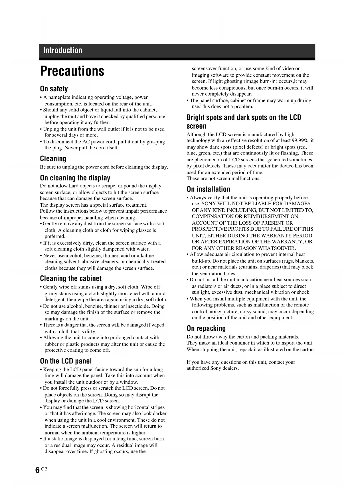
Precautions 6
Recommendations on Installation 8
Location and Function of Parts and Controls
Front....9
Rear 10
Remote Control....13
Button Description....13
Special Buttons on the Remote Control 15
Using the Wide Mode....15
Using the PAP Setting 16
Using the ID MODE button 17
Optional Adaptors 18
Connections
Connecting the Speakers....19
Connecting the AC Power Cord....19
Cable Management....20
Using the Settings
Overview of the Menus ....21
Picture/Sound Settings....22
Screen Settings....26
Setup Settings....30
Network Functions
Preparations for Using the Network Functions....34
PC Operation 36
Other Information
Troubleshooting 39
Input Signal Reference Chart....41
Specifications 43
Index 45
Introduction
Precautions
On safety
- A nameplate indicating operating voltage, power consumption, etc. is located on the rear of the unit.
- Should any solid object or liquid fall into the cabinet, unplug the unit and have it checked by qualified personnel before operating it any further.
- Unplug the unit from the wall outlet if it is not to be used for several days or more.
- To disconnect the AC power cord, pull it out by grasping the plug. Never pull the cord itself.
Cleaning
Be sure to unplug the power cord before cleaning the display.
On cleaning the display
Do not allow hard objects to scrape, or pound the display screen surface, or allow objects to hit the screen surface because that can damage the screen surface.
The display screen has a special surface treatment. Follow the instructions below to prevent impair performance because of improper handling when cleaning.
- Gently remove any dust from the screen surface with a soft cloth. A cleaning cloth or cloth for wiping glasses is preferred.
- If it is excessively dirty, clean the screen surface with a soft cleaning cloth slightly dampened with water.
- Never use alcohol, benzine, thinner, acid or alkaline cleaning solvent, abrasive cleaners, or chemically-treated cloths because they will damage the screen surface.
Cleaning the cabinet
- Gently wipe off stains using a dry, soft cloth. Wipe off grimy stains using a cloth slightly moistened with a mild detergent, then wipe the area again using a dry, soft cloth.
- Do not use alcohol, benzine, thinner or insecticide. Doing so may damage the finish of the surface or remove the markings on the unit.
- There is a danger that the screen will be damaged if wiped with a cloth that is dirty.
- Allowing the unit to come into prolonged contact with rubber or plastic products may alter the unit or cause the protective coating to come off.
On the LCD panel
- Keeping the LCD panel facing toward the sun for a long time will damage the panel. Take this into account when you install the unit outdoor or by a window.
- Do not forcefully press or scratch the LCD screen. Do not place objects on the screen. Doing so may disrupt the display or damage the LCD screen.
- You may find that the screen is showing horizontal stripes or that it has afterimage. The screen may also look darker when using the unit in a cool environment. These do not indicate a screen malfunction. The screen will return to normal when the ambient temperature is higher.
- If a static image is displayed for a long time, screen burn or a residual image may occur. A residual image will disappear over time. If ghosting occurs, use the
screensaver function, or use some kind of video or imaging software to provide constant movement on the screen. If light ghosting (image burn-in) occurs, it may become less conspicuous, but once burn-in occurs, it will never completely disappear.
- The panel surface, cabinet or frame may warm up during use. This does not a problem.
Bright spots and dark spots on the LCD screen
Although the LCD screen is manufactured by high technology with an effective resolution of at least 99.99%, it may show dark spots (pixel defects) or bright spots (red, blue, green, etc.) that are continuously lit or flashing. These are phenomenon of LCD screens that generated sometimes by pixel defects. These may occur after the device has been used for an extended period of time.
These are not screen malfunctions.
On installation
• Always verify that the unit is operating properly before use. SONY WILL NOT BE LIABLE FOR DAMAGES OF ANY KIND INCLUDING, BUT NOT LIMITED TO, COMPENSATION OR REIMBURSEMENT ON ACCOUNT OF THE LOSS OF PRESENT OR PROSPECTIVE PROFITS DUE TO FAILURE OF THIS UNIT, EITHER DURING THE WARRANTY PERIOD OR AFTER EXPIRATION OF THE WARRANTY, OR FOR ANY OTHER REASON WHATSOEVER.
- Allow adequate air circulation to prevent internal heat build-up. Do not place the unit on surfaces (rugs, blankets, etc.) or near materials (curtains, draperies) that may block the ventilation holes.
- Do not install the unit in a location near heat sources such as radiators or air ducts, or in a place subject to direct sunlight, excessive dust, mechanical vibration or shock.
- When you install multiple equipment with the unit, the following problems, such as malfunction of the remote control, noisy picture, noisy sound, may occur depending on the position of the unit and other equipment.
On repacking
Do not throw away the carton and packing materials. They make an ideal container in which to transport the unit. When shipping the unit, repack it as illustrated on the carton.
If you have any questions on this unit, contact your authorized Sony dealers.
Disposal of Waste Electrical and Electronic Equipment for business use (Applicable in the European Union and other European countries with separate collection systems)

natural_image
Symbol of a trash bin crossed with a diagonal line, no text or numbers presentThis symbol on the product or on its packaging indicates that this product shall not be treated as household waste. Instead it shall be handed over to the applicable take-back scheme for the recycling of electrical and electronic equipment. By ensuring this product is disposed of correctly, you will help prevent potential negative consequences for the environment and human health, which could otherwise be caused by inappropriate waste handling of this product. The recycling of materials will help to conserve natural resources. For more detailed information about recycling of this product, please contact your local Sony office or visit Sony Europe's web site for business customers: http://www.sonybiz.net/environment
For the State of California, USA only
Perchlorate Material – special handling may apply, See www.dtsc.ca.gov/hazardouswaste/perchlorate Perchlorate Material : Lithium battery contains perchlorate.
For the customers in the USA
Lamp in this product contains mercury. Disposal of these materials may be regulated due to environmental considerations. For disposal or recycling information, please contact your local authorities or the Electronic Industries Alliance (www.eiae.org).
For the customers in Taiwan only
廢電池請回收

Recommendations on Installation
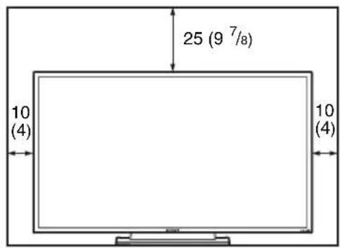
Provide an ample amount of space around the display
- To prevent internal heat buildup from sealing off the display, make sure to ensure proper ventilation by leaving open the minimum amount of space around the display, as illustrated below.
- The ambient temperature must be 0 °C to 35 °C (32 °F to 95 °F). Be careful when installing the display near a ceiling. The temperature there can become much higher than the normal, lower-level room temperature.
- When using the stand, you use the applicable Tabletop Stand SU-S01 (not supplied). For the fitting method, see the instruction manual of the Tabletop Stand.
- Regarding the installation of hardware such as brackets, screws, or bolts, we cannot specify the products. Actual installation is up to the authorized local dealers. Consult with qualified Sony personnel for installation.
- While the display is on, a certain amount of heat builds up inside. This can cause burns. Avoid touching the top or rear of the display when it is powered on or just after it has entered standby mode.
When using the Tabletop Stand
Front
text_image
25 (9 7/8) 10 (4) 10 (4)Side
10 (4)
text_image
Units: cm (inches)Note
When moving or installing the display when it is attached to the stand (not supplied), do so with at least 2 people.
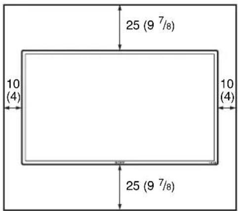
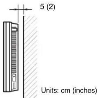
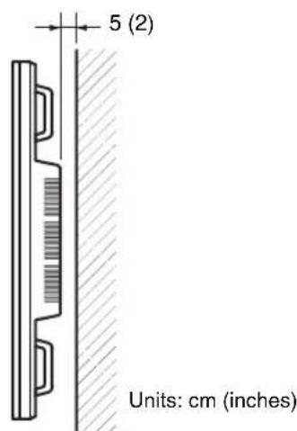
When mounting the display horizontally
Front
text_image
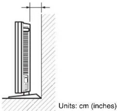
25 (9 7/8) 10 (4) 10 (4) 25 (9 7/8)Side
text_image
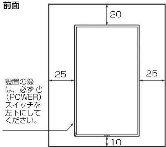
5 (2) Units: cm (inches)When mounting the display vertically
Front

text_image
Front 20 (7 7/8) 25 (9 7/8) 25 (9 7/8) 10 (4) Make sure that the ⏻ (POWER) switch is at the lower left.Side
text_image
5 (2) Units: cm (inches)Location and Function of Parts and Controls
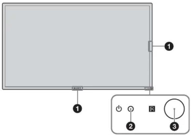
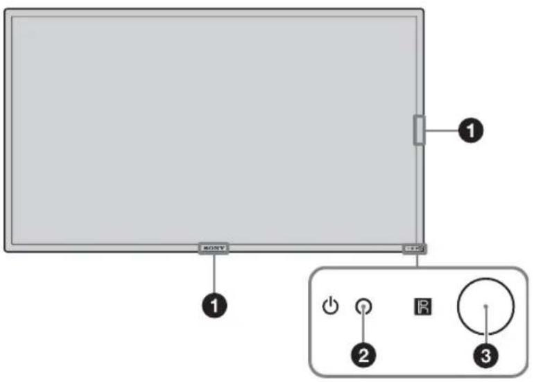
Front
text_image
1 2 3 SONY +25GB
Parts Description
| 1 Sony logo The Sony logo lights up. | |
| On the menu screen, you can change from automatic to various manual settings. See “Logo” on page 32. | |
| 2 ⏻ (Power/Stand by) indicator | Lights up in green when the display is switched on.Lights up in red when the display is in standby mode. Lights up in orange when the display enters the power saving mode while a signal is input from a PC.When the ⏻ indicator blinks in red, see page 39.NoteWhen the “LED” option in the “Multi Display” settings is set to “Off” and the “Position” option is not set to the right-bottom, the indicator does not light up in green even when the display is turned on, except for the case of no signal or an unsupported signal. |
| 3 R Remote control sensor | Remote control light receptor. |
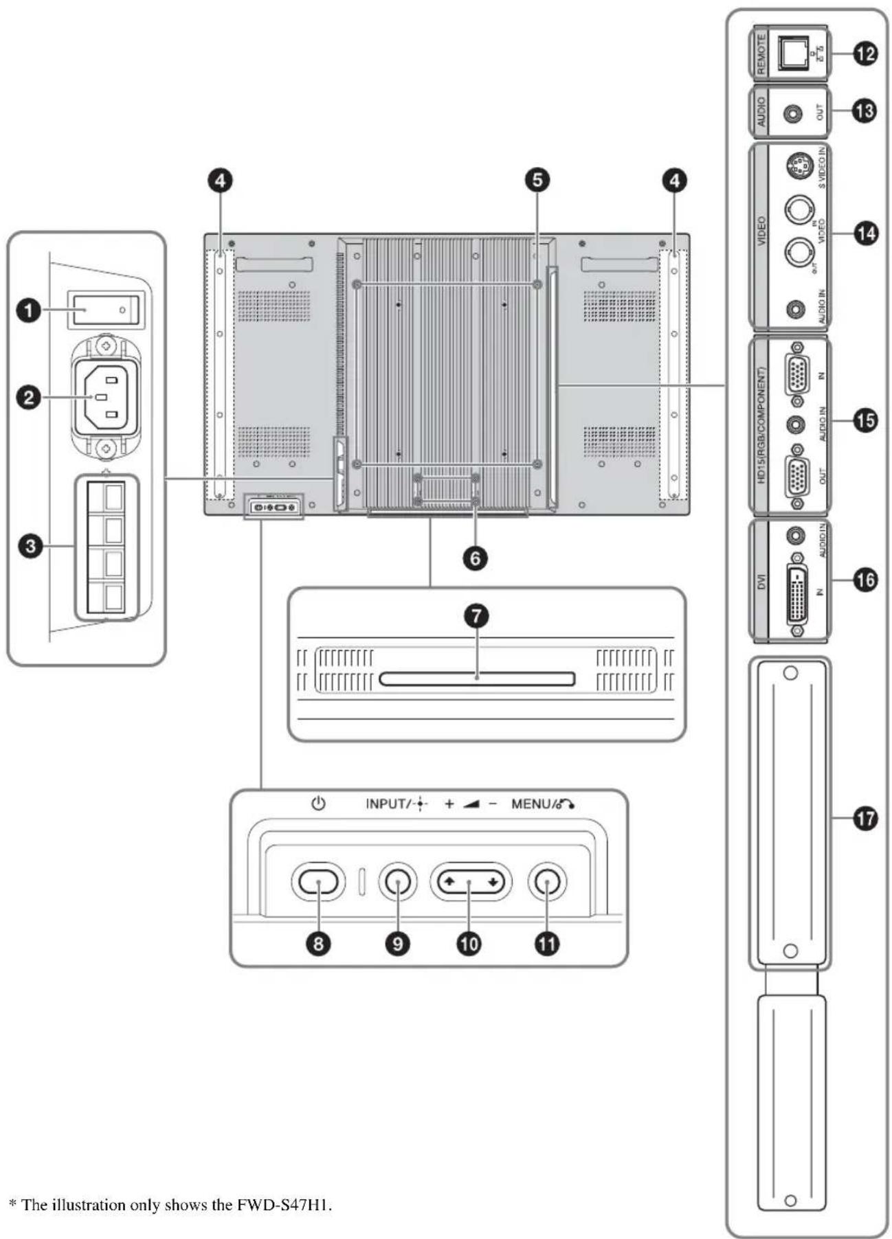
Rear
text_image
1 2 3 4 5 6 7 INPUT/+ MENU/6 8 9 10 11 12 REMOTE AUDIO OUT VIDEO S/VIDEO VHPO AUDIO IN HD15/RGB/COMPONENT AUDIO IN OUT DVI AUDIO IN N 13 14 15 16 17 * The illustration only shows the FWD-S47H1.* The illustration only shows the FWD-S47H1.
| PartsDescription | |
| 1 Main power switch | Turn the main power switch to “ON”(press the | side) when setting up the device.When the main power switch is turned “OFF” (press the ⏻de), the power consumption is 0W. |
| 2 AC IN socket | Connect the supplied AC power cord to this socket and to a wall outlet. See page 19.Once you connect the AC power cord and turn on main power switch, the ⏻ indicator lights up in red and the display goes into the standby mode. |
| 3 SPEAKER socket | Connect the speakers SS-SPG02 (not supplied) to this socket. For more details on connecting the speakers, see the operating manual that came with the speakers. For details on how to route the speaker cords, see page 20. |
| 4 Speaker installation positions | Attach the dedicated speakers SS-SPG02. |
| 5 Stand installation holes | Screw holes conforming to VESA standard. (Pitch: 400mm × 400mm, Screw: M6) |
| 6 Applicable display stand installation holes | Use these hooks to install the display stand SU-S01 (not supplied). |
| 7 Dedicated display stand installation hole cover | Remove when mounting the display stand SU-S01 (not supplied). |
| 8 ⏻ (POWER) switch | Switches the display on or off (standby).Operate when the main power switch is “ON” ( §ide). |
| 9 INPUT/+ (ENTER)button | Press to select a signal to be input from the INPUT or OPTION connector.The signal to be input switches as follows each time you press the INPUT button.S Video Video HD15 DVI OPTIONWhen an optional adaptor supporting the video signal is not installed in the OPTION slot, OPTION will be skipped.Press to set your choice. |
| 10 +/-/∅/∅ (volume/cursor) button | Press to control speaker volume. When the menu is displayed, press to move the cursor or set a value.Press to set your choice. |
| 11 MENU/(@RETURN) button | Press to show menus.This returns to the preceding menu screen. |
| 12 REMOTE (10BASE-T/100BASE-TX) | Serves to connect the display to a network, using a 10BASE-T/100BASE-TX LAN cable.You can assign various settings and control the display via the network from a PC.CautionsWhen you connect the LAN cable of the unit to peripheral device, use the supplied cable to prevent malfunction due to radiation noise.For safety, do not connect the connector for peripheral device wiring that might have excessive voltage to this port. Follow the instructions for this port.NoteWhen using this connector, select “Display” in “Network Port”. (page 32) |
| 13 AUDIO (Stereo mini jack) | This is the audio monitor output terminal for external devices. Outputs an audio of the signal currently indicated on the screen. Outputs an audio signal corresponding to the active* picture while in the “P&P” or “PinP” mode.NoteSettings assigned in “Sound Mode” or “Speaker Out” will not be reflected.The noise reduction status set by the remote control is not reflected. |
| 14VIDEO | S VIDEO IN(Mini DIN 4-pin): Connects to the S Video output of a piece of video equipment.VIDEO IN(BNC): Connects to the video output of a piece of video equipment.VIDEO OUT(BNC): Connects to the video input of a piece of video equipment. Pictures input from VIDEO IN will be output.AUDIO IN(Stereo mini jack): Connects to the audio output of a piece of video equipment. |
| 15HD15 (RGB/COMPONENT)(D-sub 15-pin) | HD15 (RGB/COMPONENT)IN:Connects to the analog RGB signal or component signal output of a piece of video equipment or PC. See page 44.AUDIO IN:Inputs an audio signal. Connects to the audio signal output of a piece of video equipment or PC.HD15 (RGB/COMPONENT)OUT:Connects to the analog RGB signal or component signal input of a piece of video equipment or PC. See page 44. Signals input from the HD15 (RGB/COMPONENT) IN connector above will be output.NotesWhen inputting a component signal, be sure not to input sync signals to pins 13 and 14. If you do so, the picture may not be displayed properly.When the display is not connected to an AC power or is in the standby mode, no signal is output from the HD15 (RGB/COMPONENT) OUT. |
| 16DVI(DVI-D 24-pin) | DVI IN:Connects to the digital signal output terminal of the video equipment or PC.Supports HDCP copy protection.AUDIO IN:Inputs an audio signal. Connects to the audio signal output of a piece of video equipment, etc. |
| 17OPTION slot(VIDEO/COM port) | This slot supports video signals and communication functions. Attach an optional adaptor (the BKM-FW series) in this slot to extend monitor functions. See page 18. |
* The status when the sound is output and the input signal can be switched.
Remote Control
Button Description
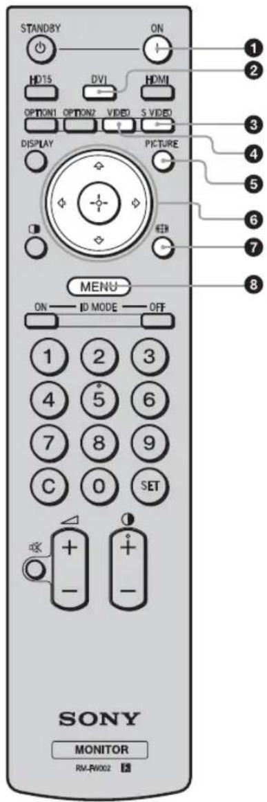
text_image
STANDBY ON HD15 DVI HDMI OPTION1 OPTION2 VIDEO S VIDEO DISPLAY PICTURE MENU ON ID MODE OFF 1 2 3 4 5 6 7 8 9 C 0 SET + - + - SONY MONITOR RW-RW002① POWER ON switch
Press to turn the display on.
Operate when the main power switch on the backside of the display is "ON."
②DVI button
Press to select the signal input to the DVI port.
③S VIDEO button
Press to select the signal input to the S VIDEO IN connector from a piece of video equipment.
④VIDEO button
Press to select the signal input to the VIDEO IN connector from a piece of video equipment.
⑤PICTURE button
Selects "Picture Mode". Each press toggles between "Vivid", "Standard", "Custom", "Conference", and "TC Control".
6 ↑/↓/↔/→/⊕ buttons
The ♣/▽/⇨/⇨ buttons move the menu cursor and set values, etc. Pressing Ⓛsets the selected menu or setting items. In the “PAP” mode, you can switch the Picture and Picture setting. See page 16.
⑦ button
Press to change the aspect ratio. See page 15.
⑧MENU button
Press to show menus. Press again to hide them. See page 21.
Notes
- The 5 button and Ⓞ button have a tactile dot. Use the tactile dot as a reference when operating the display.
- Insert two size AA (R6) batteries (supplied) by matching the and on the batteries to the diagram inside the remote control's battery compartment.
Caution
Danger of explosion if battery is incorrectly replaced. Replace only with the same or equivalent type recommended by the manufacturer. When you dispose of the battery, you must obey the law in the relative area or country.
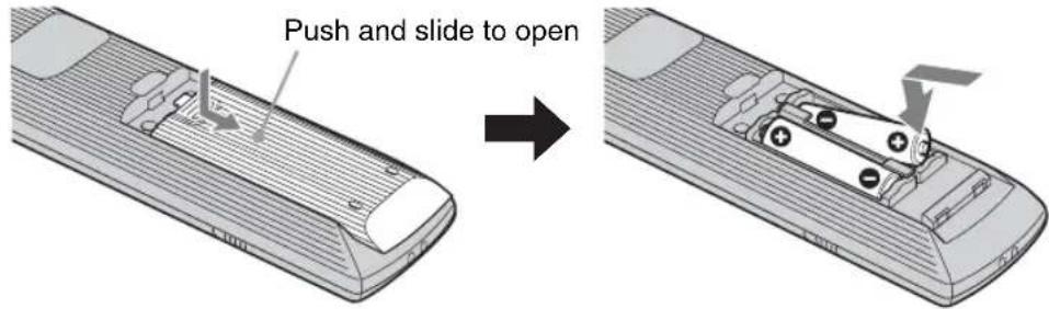
text_image
Push and slide to open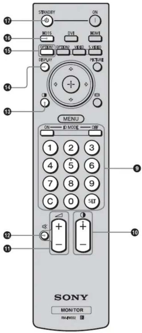
text_image
STANDBY ON HD15 DVI HDMI OPTION1 OPTION2 VIDEO S VIDEO DISPLAY PICTURE MENU ON ID MODE OFF 1 2 3 4 5 6 7 8 9 C 0 SET SONY MONITOR RM-FA002⑨ID MODE (ON/0-9/SET/C/OFF) buttons
You can operate a specific display without affecting other displays installed at the same time.
- ON button: Press to show the "Index Number" on the screen.
- 0-9 button: Press to enter the "Index Number" of the display you want to operate.
- SET button: Press to set the input "Index Number".
- C button: Press to clear the input "Index Number".
- OFF button: Press to return to the normal mode.
See page 17.
10 +/- button
Adjusts the picture (contrast) level.
⑪ +/- button
Press to adjust the volume.
⑫ button
Press to mute the sound. Press again to restore sound.
⑬ button
Selects the "PAP" (Picture And Picture) mode. Each press toggles between "P&P", "PinP" and the single-screen picture. See page 16.
⑭DISPLAY button
Press to display the currently selected input, the type of the input signal and the "Aspect" setting on the screen. Press again to hide them. If this displayed information is left undisturbed for a short time, it will disappear automatically.
⑮OPTION 1 button
When an optional adaptor is installed, selects an input signal from the equipment connected to the optional adaptor.
If the installed optional adaptor has multiple input connectors, each press of the button toggles between the input signals.
16HD15 button
Press to select the input signal of the HD15 (RGB/COMPONENT) connector. The RGB signal or component signal is selected automatically or manually in accordance with the menu settings.
⑰ STANDBY button
Press to change the display to the standby mode.
Note
You cannot use the HDMI button and the OPTION 2 button on this display.
Special Buttons on the Remote Control
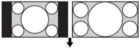
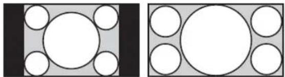
Using the Wide Mode
You can change the aspect ratio of the screen.
Tip
You can also access the "Aspect" settings in the "Screen" settings. See page 28, 29.
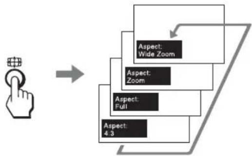
flowchart
graph TD
    A["User Hand Press"] --> B["Arrow"]
    B --> C["Aspect: Wide Zoom"]
    B --> D["Aspect: Zoom"]
    B --> E["Aspect: Full"]
    B --> F["Aspect: 4.3"]
    C --> G["Arrow"]
    D --> G
    E --> G
    F --> G
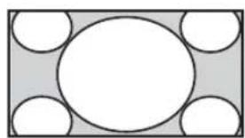
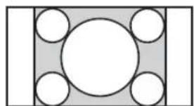
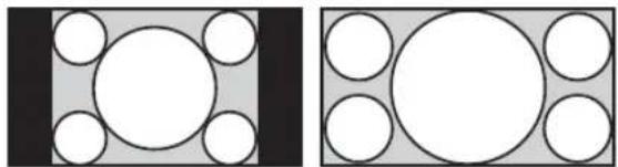
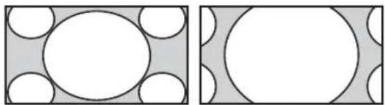
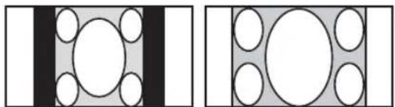
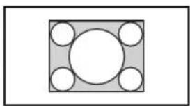
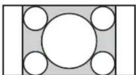
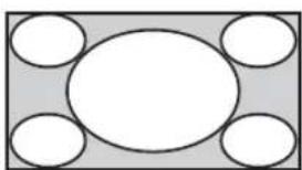
For input from video equipment such as Video, DVD, etc. (other than PC input)
4:3 Original Source
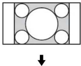
natural_image
Diagram showing a rectangular block with five circular holes and a downward arrow, no text or symbols present.Wide Zoom

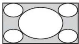
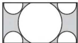
natural_image
Simple geometric diagram with a central circle surrounded by four smaller circles, no text or symbols present.Zoom
natural_image
Geometric diagram with a central circle surrounded by smaller semicircles and rectangles (no text or symbols)Full
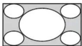
natural_image
Simple geometric diagram with five white circles arranged around a central oval (no text or symbols)4:3
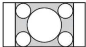
natural_image
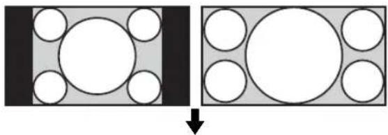
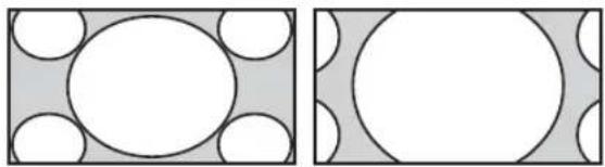
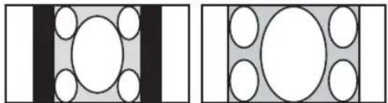
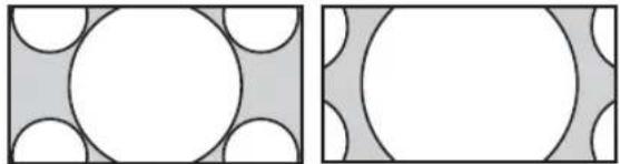
Simple geometric diagram with a central circle surrounded by four smaller circles, enclosed in a rectangle (no text or symbols)16:9 Original source
natural_image
Diagram showing two rectangular blocks with circles inside, one black and one gray, both before and after a downward arrow (no text or symbols)Wide Zoom
natural_image
Two geometric diagrams showing circles and rectangles with shaded regions, no text or symbols present.Zoom
natural_image
Two abstract geometric patterns: one with white circles on a gray background, the other with white circles on a gray background (no text or symbols)Full
natural_image
Two geometric diagrams showing circles arranged in a grid, one with a central circle and the other with an oval (no text or symbols)4:3
natural_image
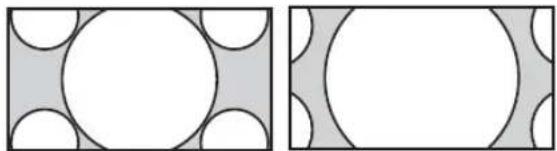
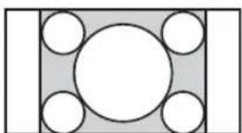
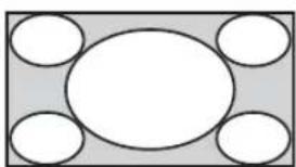
Two abstract geometric diagrams with circles and rectangles, no text or symbols presentFor PC Input
Illustrations below indicate the input resolution of 800×600
Real
natural_image
Simple geometric diagram with a central circle surrounded by four smaller circles, enclosed in a square frame (no text or symbols)Full 1
natural_image
Geometric diagram with a central circle surrounded by six smaller circles, enclosed in a rectangle (no text or symbols)Full 2
natural_image
Simple diagram with a central oval and four surrounding empty circles, no text or symbols present.Note
If the input resolution is higher than the panel resolution (1,920× 1,080) , the display of Real is the same as Full 1.
Using the PAP Setting
You can show two pictures from different signal sources, such as a PC and a video, side by side. You can also swap the active pictures, or change the balance of picture sizes. You can also access the "PAP Setting" in the "Screen" settings. See page 26.


Cursor showing active picture
For P&P
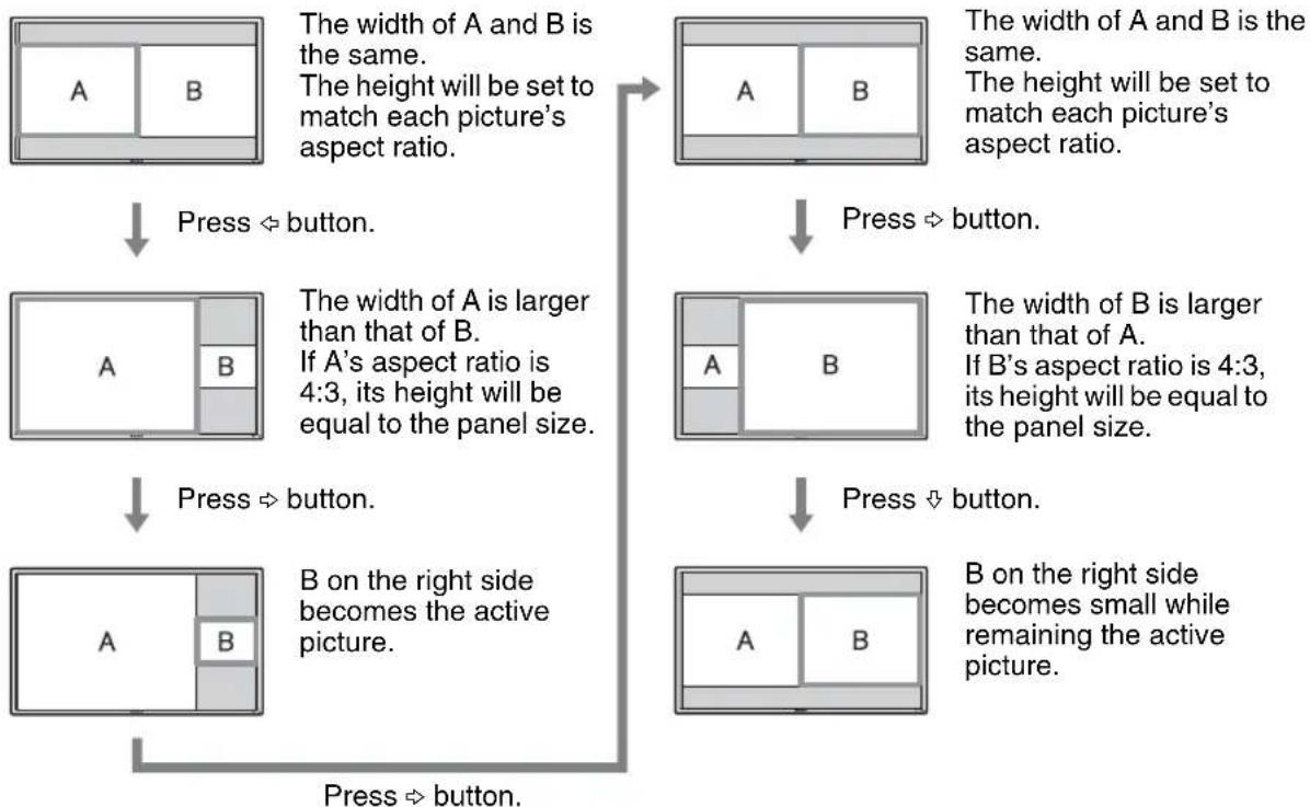
flowchart
graph TD
    A["Rectangle with sides A and B"] -->|Press ⇌ button.| B["Rectangle with dimensions A and B"]
    B -->|Press ⇒ button.| C["Rectangle with dimensions A and B"]
    C -->|Press ⇒ button.| D["Rectangle with dimensions A and B"]
    D -->|Press ⇒ button.| E["Rectangle with dimensions A and B"]
    style A fill:#f9f,stroke:#333
    style B fill:#f9f,stroke:#333
    style C fill:#f9f,stroke:#333
    style D fill:#f9f,stroke:#333
    style E fill:#f9f,stroke:#333
For PinP
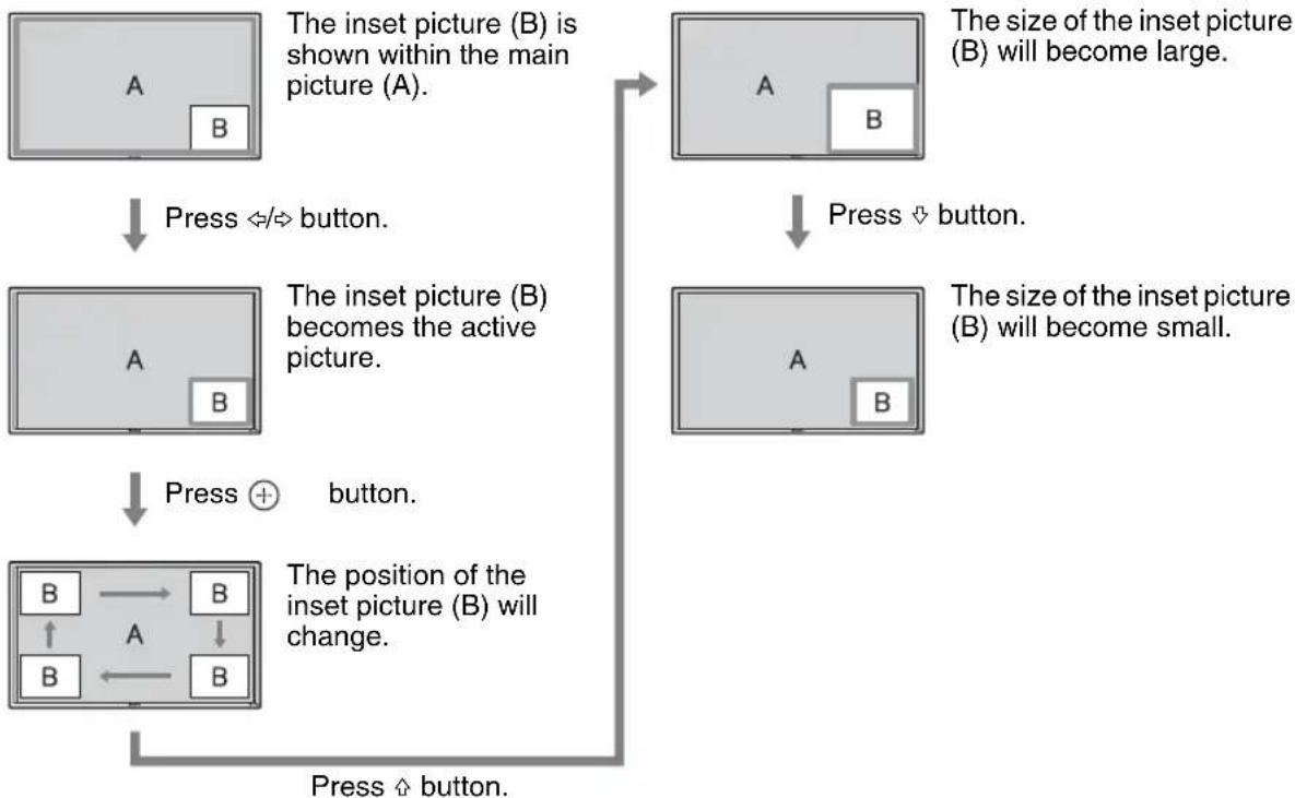
flowchart
graph TD
    A["The inset picture (B) is shown within the main picture (A)."] -->|Press ⇔/⇔ button.| B["The inset picture (B) becomes the active picture."]
    B -->|Press ⊕ button.| C["The position of the inset picture (B) will change."]
    C -->|Press ↗ button.| D["The size of the inset picture (B) will become large."]
    D -->|Press ↘ button.| E["The size of the inset picture (B) will become small."]
Tips
- The cursor indicating the active picture will disappear after 5 seconds.
• The picture can be adjusted to 15 sizes. (For P&P)
Using the ID MODE button
You can operate a specific display without affecting other displays installed at the same time.
1 Press ON button.
Display's "Index Number" appears in black characters on the lower left menu on the screen. (Every display is allocated an individual preset "Index Number" from 1 to 255.)
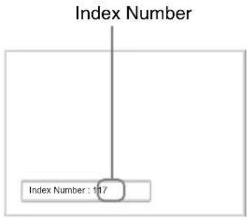
text_image
Index Number Index Number : 1.17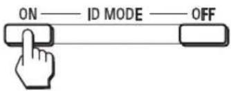
text_image
ON —— ID MODE —— OFF2 Input the "Index Number" of the display you want to operate using the 0 - 9 buttons on the remote control.
The input number appears right next to the “Index Number” of each display.
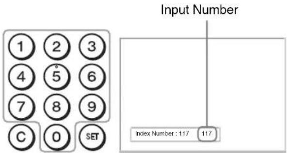
text_image
Input Number 1 2 3 4 5 6 7 8 9 C 0 SET Index Number : 117 1173 Press SET button.
The characters on the selected display change to green while the others change to red.

You can operate the specified display indicated with green characters only.
Only the operation of POWER ON switch and STANDBY/ID MODE-OFF button is effective to other displays, as well.
4 When all of the setting changes have been completed, press OFF button.
The display returns to the normal screen.
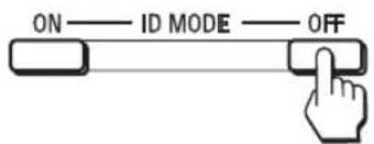
text_image
ON — ID MODE — OFFTo correct the Index Number
Press the C button to clear the current input "Index Number". Return to Step 2, and input a new "Index Number".

Tip
To change the "Index Number" of the display, see "Index Number" in "Control Setting" on page 30.
Optional Adaptors
The terminal of the OPTION slot 17 (page 12) on the side of the equipment is a slot-in type. It can be switched to the following optional adapter (not supplied).
For details on installation, consult your Sony dealers. For details on the optional adaptors for system expansion, see each instruction manual with this manual.
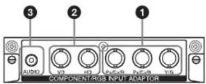
COMPONENT/RGB INPUT Adaptor BKM-FW11
text_image
3 2 1 AUDIO V0 HD Pout/RSG Put/RSG V8 COMPONENT/RGS INPUT ADAPTOR①Y/G, P_B/C_B/B, P_R/C_R/R IN (BNC): Connects to the analog RGB signal or component signal output of a piece of video equipment or PC.
②HD, VD IN (BNC): Connects to the synchronization signal output of a PC.
Note
When inputting a component signal, be sure not to input sync signals to the HD and VD connectors. If you do so, the picture may not be displayed properly.
3 AUDIO (Stereo mini jack): Inputs an audio signal. Connects to the audio output of a piece of video equipment or PC.
HDMI INPUT Adaptor BKM-FW15
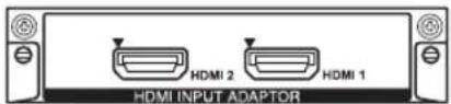
You can enjoy enhanced or high-definition video, and two-channel digital audio.
The appropriate mode for a piece of audio/video equipment or PC is automatically selected in accordance with the connected equipment.
Note
Be sure to use only an HDMI cable (not supplied) that bears the HDMI logo.
HD-SDI/SDI INPUT Adaptor BKM-FW16
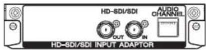
text_image
HD-SDI/SDI AUDIO CHANNEL OUT IN HD-SDI/SDI INPUT ADAPTORConnects to the HD-SDI signal output of a piece of video equipment.
MONITOR CONTROL Adaptor BKM-FW21
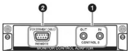
text_image
FORESTMENT CABLE REMOTE OUT IN CONTROL 5 MONITOR CONTROL ADAPTOR1CONTROL S IN/OUT (Mini jack): You can control pieces of multiple equipment with a single remote control when the display is connected to the CONTROL S connector of the video equipment or another display. Connect the CONTROL S OUT connector on this adaptor to the CONTROL S IN connector of the other equipment, and connect the CONTROL S IN connector on this adaptor to the CONTROL S OUT connector of the other equipment.
②REMOTE (D-sub 9-pin): This connector allows remote control of the display using the RS-232C protocol. For details, contact your authorized Sony dealers.
Notes
- The REMOTE connector and the REMOTE (LAN) connector 12 (page 11) on the side of the equipment cannot be used at the same time.
- When using the REMOTE connector, select "Option" in "Network Port". (page 32)
STREAMING RECEIVER Adaptor BKM-FW50
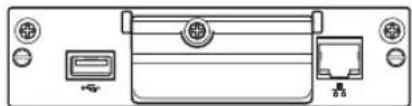
natural_image
Front view of a computer interface panel with ports and indicators (no text or symbols)This adaptor enables you to use this display for digital signage.
You can easily play back movies, still images or background music in designated data formats by just inserting a recording media. You can also use a network to view images from a remote computer on the display.
Note
A compact flash memory card is required.
Connections
Before you start
- First make sure that the power of each piece of equipment is turned off.
- Use cables suitable for the equipment to be connected.
- Connect the cables, fully inserting them into the connectors or jacks. A loose connection may cause hum and other noise.
- To disconnect the cable, pull it out by grasping the plug. Never pull the cable itself.
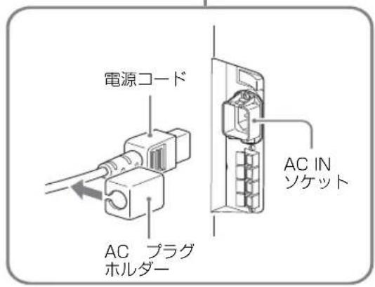
• See the instruction manual of the equipment to be connected, too. - Insert the plug securely into the AC IN socket.
- Use one of the two AC plug holders (supplied) to securely hold the AC plug.
Connecting the Speakers
Connect the speakers SS-SPG02 (not supplied). Please be sure to connect the speakers correctly. For more details on connecting the speakers, see the operating manual of the speakers. For details on how to route the speaker cords, see page 20.
Connecting the AC Power Cord
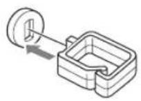
1 Plug the AC power cord into the AC IN socket. Then, attach the AC plug holder (supplied) to the AC power cord.
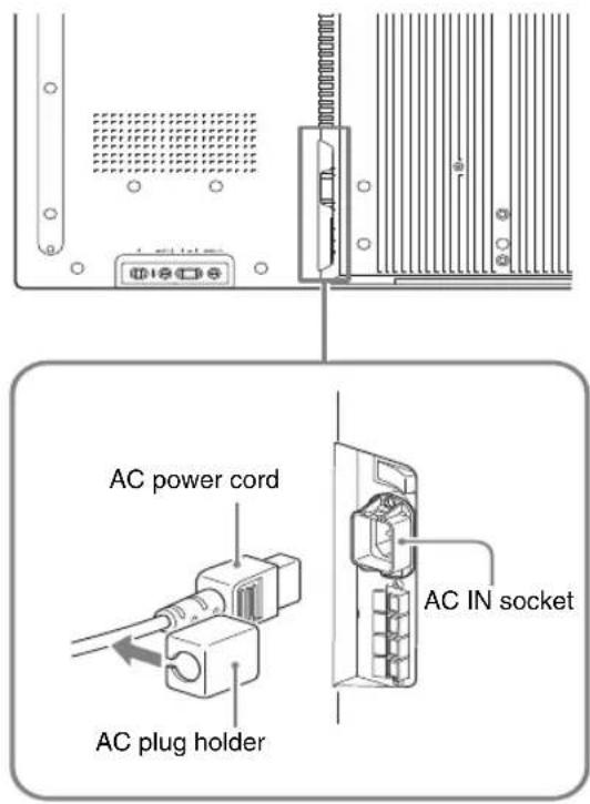
text_image
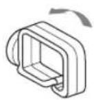
AC power cord AC plug holder AC IN socket2 Slide the AC plug holder over the cord until it connects to the AC IN socket cover.
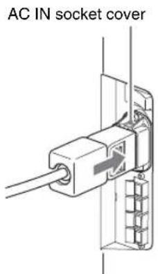
text_image
AC IN socket coverTo remove the AC power cord
After squeezing the AC plug holder and freeing it, grasp the plug and pull out the AC power cord.
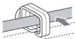
Cable Management
Using the cable holders
You can neatly bundle the cables with the cable holders ( ×9 ) provided. Attach the cable holders as shown in the illustrations below.
Rear
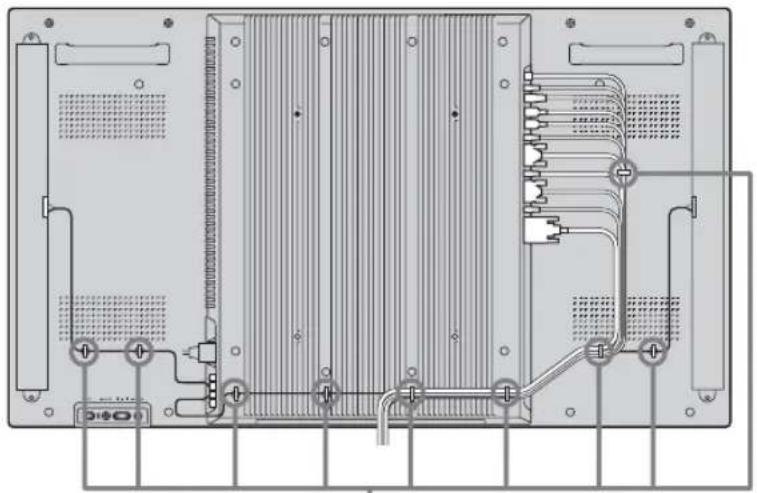
natural_image
Technical diagram of an electronic device rear panel with internal circuitry and connectors (no text or labels)①

②

③
Using the Settings
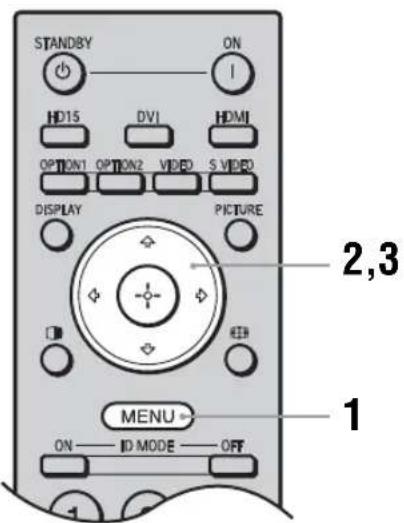
Overview of the Menus
text_image
STANDBY ON HD15 DVI HDMI OPTION1 OPTION2 VIDEO S VIDEO DISPLAY PICTURE 2,3 MENU ON —— ID MODE —— OFF 1The settings provide you access to the following features:
1 Press MENU button.
2 Press ↗/▽ to highlight the desired menu icon.
3 Press ⊕ or ➔.
To exit the menu, press MENU button.
To change the on-screen language
Select the desired language for on-screen settings and messages from “English”, “Français”, “Deutsch”, “Español”, “Italiano” or “日本語” English (English) is set for the default setting. See page 30.
Settings Allows you to set/change
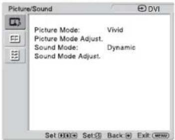
Picture/Sound
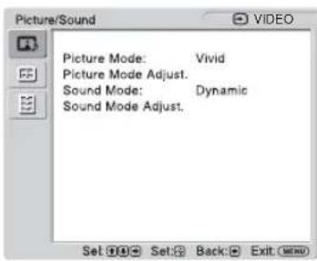
text_image
Picture/Sound Picture Mode: Vivid Picture Mode Adjust. Sound Mode: Dynamic Sound Mode Adjust. Set: Set: Back: Exit (Enter)Picture Mode: (page 22, 24) Picture Mode Adjust. (page 22, 24) Sound Mode: (page 23, 25) Sound Mode Adjust. (page 23, 25)
Note
You cannot set or change "Picture Mode" or "Picture Mode Adjust." when there is no signal input.
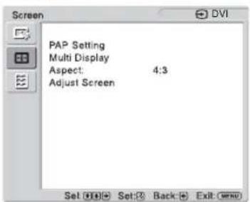
Screen
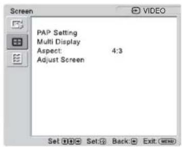
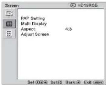
text_image
Screen PAP Setting Multi Display Aspect: 4:3 Adjust Screen Set Ⓧ️ Set:② Back: Exit Ⓧ️PAP Setting (page 26, 29) Multi Display (page 27, 29) Aspect: (page 28, 29) Adjust Screen (page 28, 29)
Setup
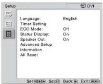
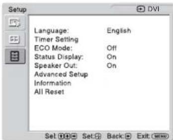
text_image
Setup Language: English Timer Setting ECO Mode: Off Status Display: On Speaker Out: On Advanced Setup Information All Reset Set Ⓧ Set: Back: Exit (Enter)Language: (page 30) Timer Setting (page 30) ECO Mode: (page 30) Status Display: (page 30) Speaker Out: (page 30) Advanced Setup (page 30) Information (page 33) All Reset (page 33)

Picture/Sound Settings
For Video Input
text_image
Picture/Sound Picture Mode: Vivid Picture Mode Adjust. Sound Mode: Dynamic Sound Mode Adjust. Set Set Back ExitTo highlight an option and to change settings, press /// .
Press ⓣ to confirm the selection.
The “Picture/Sound” settings include the following options:
Picture Mode
"Vivid": Select for enhanced picture contrast and sharpness.
"Standard": Select for standard picture settings.
"Custom": Allows you to store preferred settings.
“Conference”: Adjusts the picture quality for video conferencing under fluorescent lights.
"TC Control": The setting is common with "Vivid". In addition, you can use the "True Color Control" function (after-mentioned).
Tip
To change from one "Picture Mode" option to another, you can also use PICTURE on the remote control instead.
Notes
- “Conference” may not be effective depending on the environment or the video conference system under use. In this case, adjust the picture quality, switch to other settings of “Picture Mode”, etc.
- In "TC Control", "Brightness Boost" is fixed to Off.
Picture Mode Adjust.
"Backlight": Adjusts to brighten or darken the screen.
"Contrast": Adjusts picture contrast.
"Brightness": Adjusts to brighten or darken the picture.
"Chroma": Adjusts to increase or decrease color intensity.
“Phase”: Adjusts the color tones of the picture.
“Sharpness”: Adjusts to sharpen or soften the picture.
“Noise Reduction”: Select to reduce the noise level of connected equipment. Select from “Off”, “Low”, “Mid”, “High” to set the noise level.
“CineMotion”: Select “Auto” to optimize the screen display automatically detecting film content and applying a reverse 3-2 pull down or 2-2 pull down process. Moving picture will appear clearer and more natural looking. Select “Off” to disable the detection.
“Dynamic Picture”: Select “On” to enhance contrast by making white brighter and black darker.
"Gamma Correct.": Balances the light and dark portions of pictures. Select from "High", "Mid", "Low" to make settings.
Notes
- “Option” can only be set when there is a DVI input.
- Gamma setting is in accordance with the Grayscale Standard Display Function (GSDF) of the Digital Imaging and Communications in Medicine (DICOM) standards. However, this setting is for reference only and cannot be used for medical diagnosis.
"Color Temp.": White tone can be adjusted to suit your preference. The factory default settings are adjusted to color temperature.
"Cool": Select to give the white colors a blue tint.
"Neutral": Select to give the white colors a neutral tint.
"Warm": Select to give the white colors a red tint.
"Custom": Enables a broader range of white tone to be set than above.
Tip
Restores the default settings by selecting "Reset" on the tone adjusting screen.
“Brightness Boost”: Emphasizes the brightness of the image.
Notes
- When “Brightness Boost” is set to “On”, you cannot adjust the “Backlight”, “Contrast”, “Brightness” or “Color Temp.” settings.
- When “Brightness Boost” is set to “On” and “ECO Mode” is switched “Off”, the brightness is at its maximum.
“True Color Control”: You can adjust the details of hue and saturation for each of 4 colors: red, green, yellow, blue, and you can highlight specific colors in the image. Select the color which you want to adjust, and you can check and see which part of current image will be adjusted. Then you can adjust it using the matrix dialog.
Notes
- This option can be adjusted when "Picture Mode" is set to "TC Control".
- In “PAP” mode, you cannot select this option. Even if you select this option in the single-picture screen, the setting of this option may not be applied in the “PAP” mode
“Reset”: Resets all settings of “Picture Mode Adjust.” to default settings.
Notes
- “Phase” is not available when the input is Video or S Video and the color system of video signal is not NTSC.
- “Dynamic Picture” is not available when “Picture Mode” is set to “Conference” or “TC Control.”
- You can make settings and adjustments for each “Picture Mode” but “Backlight,” “Noise Reduction” and “CineMotion” settings are common for all “Picture Mode.”
- “Dynamic Picture” and “CineMotion” do not function in PAP mode.
| Sound Mode | You can adjust the sound output from the speakers SS-SPG02 (not supplied) with various “Sound Mode” settings.“Dynamic”: Select to enhance treble and bass.“Standard”: Flat setting.“Custom”: Allows you to store preferred settings. |
| Sound Mode Adjust. | “Treble”: Adjusts to increase or decrease higher-pitched sounds.“Bass”: Adjusts to increase or decrease lower-pitched sounds.“Balance”: Adjusts to emphasize left or right speaker balance.“Surround”: Select the surround mode according to the type of picture.“Off”: No surround output.“Hall”: When desiring to give the stereo sound of movies or music programs a greater sense of presence.“Simul.”: When desiring to give ordinary monaural programs or news telecasts an enhanced sense of presence using simulated stereo sound.“Reset”: Resets all settings of “Sound Mode Adjust.” to default settings. |
Tips
- You can alter the “Picture Mode Adjust.” settings (“Contrast”, “Brightness”, “Chroma”, etc.) for each “Picture Mode”.
- You can adjust the “Sound Mode Adjust.” settings (“Treble” and “Bass”) when the “Sound Mode” is set to “Custom”.
Note
In the “PAP” mode, only “Picture/Sound” settings for the active picture can be adjusted.
For PC Input
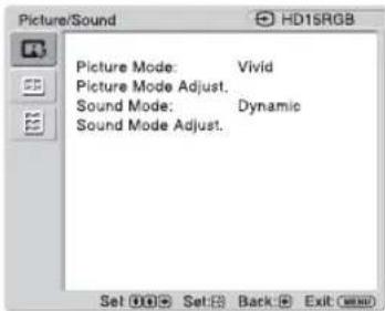
text_image
Picture/Sound HD15RGB Picture Mode: Vivid Picture Mode Adjust. Sound Mode: Dynamic Sound Mode Adjust. Set Off Set Back ExitWhen input is switched to a PC input source, the "Picture/Sound" settings specific to PC input are applied.
The “Picture/Sound” settings for a PC include the following options:
Picture Mode
"Vivid": Select for enhanced picture contrast and sharpness.
"Standard": Select for standard picture settings.
"Custom": Allows you to store preferred settings.
“Conference”: Adjusts the picture quality for video conferencing under fluorescent lights.
“TC Control”: The setting is common with “Vivid”. In addition, you can use the “True Color Control” function (after-mentioned).
Tip
To change from one "Picture Mode" option to another, you can also use PICTURE on the remote control instead.
Notes
- “Conference” may not be effective depending on the environment or the video conference system under use. In this case, adjust the picture quality, switch to other settings of “Picture Mode”, etc.
- In "TC Control", "Brightness Boost" is fixed to Off.
Picture Mode Adjust.
"Backlight": Adjusts to brighten or darken the screen.
"Contrast": Adjusts picture contrast.
“Brightness”: Adjusts to brighten or darken the picture.
"Gamma Correct.": Balances the light and dark portions of pictures. Select from "High", "Mid", "Low" to make settings.
Notes
- "Option" can only be set when there is a DVI input.
- Gamma setting is in accordance with the Grayscale Standard Display Function (GSDF) of the Digital Imaging and Communications in Medicine (DICOM) standards. However, this setting is for reference only and cannot be used for medical diagnosis.
"Color Temp.": White tone can be adjusted to suit your preference. The factory default settings are adjusted to color temperature.
"Cool": Select to give the white colors a blue tint.
"Neutral": Select to give the white colors a neutral tint.
"Warm": Select to give the white colors a red tint.
"Custom": Enables a broader range of white tone to be set than above.
Tip
Restores the default settings by selecting "Reset" on the tone adjusting screen.
"Brightness Boost": Emphasizes the brightness of the image.
Notes
- When "Brightness Boost" is set to "On", you cannot adjust the "Backlight", "Contrast", "Brightness" or "Color Temp." settings.
- When “Brightness Boost” is set to “On” and “ECO Mode” is switched “Off”, the brightness is at its maximum.
"True Color Control": You can adjust the details of hue and saturation for each of 4 colors: red, green, yellow, blue, and you can highlight specific colors in the image. Select the color which you want to adjust, and you can check and see which part of current image will be adjusted. Then you can adjust it using the matrix dialog.
Notes
- This option can be adjusted when "Picture Mode" is set to "TC Control".
- In “PAP” mode, you cannot select this option. Even if you select this option in the single-picture screen, the setting of this option may not be applied in the “PAP” mode
“Reset”: Resets all settings of “Picture Mode Adjust.” to default settings.
Note
You can make settings and adjustments for each “Picture Mode” but “Backlight” is common for all “Picture Mode.”
Sound Mode
You can adjust the sound output from the speakers SS-SPG02 (not supplied) with various “Sound Mode” settings.
"Dynamic": Select to enhance treble and bass.
"Standard": Flat setting.
"Custom": Allows you to store preferred settings.
Sound Mode Adjust.
"Treble": Adjusts to increase or decrease higher-pitched sounds.
“Bass”: Adjusts to increase or decrease lower-pitched sounds.
“Balance”: Adjusts to emphasize left or right speaker balance.
“Surround”: Select the surround mode according to the type of picture.
"Off": No surround output.
“Hall”: When desiring to give the stereo sound of movies or music programs a greater sense of presence.
“Simul.”: When desiring to give ordinary monaural programs or news telecasts an enhanced sense of presence using simulated stereo sound.
“Reset”: Resets all settings of “Sound Mode Adjust.” to default settings.
Tips
- You can alter the “Picture Mode Adjust.” settings (“Contrast”, “Brightness”, “Chroma”, etc.) for each “Picture Mode”.
- You can adjust the “Sound Mode Adjust.” settings (“Treble” and “Bass”) when the “Sound Mode” is set to “Custom”.
Notes
- “Chroma”, “Phase”, “Sharpness”, “Noise Reduction”, “CineMotion”, and “Dynamic Picture” are not available for PC input.
- In the “PAP” mode, only “Picture/Sound” settings for the active picture can be adjusted.

Screen Settings
For Video Input
text_image
Screen PAP Setting Multi Display Aspect: 4:3 Adjust Screen Set Set Back ExitTo highlight an option and to change settings, press /// .
Press ⓣ to confirm the selection.
The "Screen" settings include the following options:
PAP Setting
Allows you to show two pictures from different signal sources, such as a PC and a video, side by side.
"PAP"
"Off": Disables "PAP" function.
“P&P”: Shows two pictures side by side at the same time.
"PinP": Displays two pictures as the inset picture within the main picture.
For P&P
"Active Picture": Selects the screen to operate.
"Left": You can activate the left picture to operate it.
"Right": You can activate the right picture to operate it.
"Swap": Swaps the two pictures side by side.
"Picture Size": Adjusts the balance between two pictures side by side. Adjust the balance by pressing or button, and then press button to set the adjustment. (page 16)
For PinP
"Active Picture": Selects the screen to operate.
"Main": You can activate the main picture to operate it.
"Sub": You can activate the inset picture to operate it.
"Swap": Swaps the main and the inset pictures.
"Picture Size": Adjusts the size of the inset picture. Select from "Large" or "Small".
“Picture Position”: Adjusts the position of the inset picture with ⊕/▽/↔/↔, then press ⊕.
Tip
You cannot change the aspect ratio in the "PAP" mode. The picture is displayed in the last aspect ratio used prior to selecting "PAP" mode.
Available combination of two pictures
1) Supported when "Display" is set to "YUV" or when "Option" is set to "RGB" in "RGB/YUV".
2) Supported when "Display" is set to "RGB" or when "Option" is set to "YUV" in "RGB/YUV".
Tip
Output from BKM-FW50 is considered as RGB output shown in the table in the "PAP" mode.
Multi Display
Allows you to make settings for connecting multiple displays to form a video wall. "Multi Display"
"Off": Uses a single screen.
“2×2”/“3×3”/“4×4”: Sets to connect multiple displays such as 2, 3 or 4 displays both vertically and horizontally.
“1×2”/“1×3”/“1×4”: Sets to connect multiple displays such as 2, 3 or 4 displays horizontally.
“2×1”/“3×1”/“4×1”: Sets to connect multiple displays such as 2, 3 or 4 displays vertically.
"Position": Select the position of each display in the arrangement of the video wall with /// . Press to set the position.
"Output Format": Selection of two picture output formats will be available as shown in the figures. By simply selecting either format, suitable picture output will be available without manually adjusting the horizontal and vertical shift. Select either "Tiles" or "Window".
"Tiles"
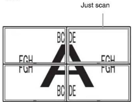
text_image
Just scan BC DE FCH FCH FGH FGH A BC DETo show full signal on each display.
"Window"
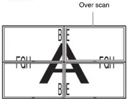
text_image
Over scan BE FQH A FQH BE FQHTo show one large picture with multi display naturally. Part of the signal will go behind the bezel area.
“LED”: “On” makes the ⏻ indicator on the front panel (page 9) to be continually turned on, and “Off” makes the ⏻ indicator on the front panel to be continually turned off.
Notes
- “Multi Display” can display an enlarged picture keeping the current “Aspect” setting as much as possible for video input, and can display an enlarged picture of which “Aspect” is set to “Full 2” for PC input.
- You can set the "Multi Display" only when the "PAP" function is disabled.
- When “Position” is set to the right-bottom, the ⏻ indicator lights up even if “LED” is set to “Off”. The indicator also lights up even when the display is off (standby), errors are detected, or the display is in sleep mode including the case of no signal or unsupported signal.
| Aspect | “Wide Zoom”: Select to enlarge to fill screen with minimum distortion.“Zoom”: Select to enlarge the original picture without distorting the aspect ratio.See page 15.“Full”: Select to enlarge the original picture horizontally to fill the screen when the original source is 4:3 (Standard definition source). When the original source is 16:9 (High definition source), select this mode to display 16:9 picture in original size.“4:3”: Select to display all the pictures in original size to 4:3 aspect ratio..TipsTo change from one “Aspect” option to another, you can also use 📋 on the remote control.Select “Zoom” to display movies and other DVD content with black bands, using the entire viewable area of the screen.NoteYou cannot set the “Aspect” while using the “PAP” function or the “Multi Display”. |
| Adjust Screen | “H Size”: Allows you to adjust the size of the picture horizontally. Press ⇔/⇨ and press ⏻to choose a correction.“H Shift”: Allows you to move the position of the picture left and right in the window. Press ⇔/⇨ and press ⭕ to choose a correction.“V Size”: Allows you to adjust the size of the picture vertically. Press ⇔/⇨ and press ⭕ to choose a correction.“V Shift”: Allows you to move the position of the picture up and down in the window. Press ⇔/⇨ and press ⭕ to choose a correction.“Reset”: Resets all settings of “Adjust Screen” to default settings. |
Notes
- “Adjust Screen” is not available while using the “PAP” function.
- If there is no signal currently being input, none of the “Screen” settings options, except for “PAP Setting” and “Multi Display” can be selected.
For PC Input
text_image
Screen PAP Setting Multi Display Aspect: 4:3 Adjust Screen Set Ⓧ Set: Back ExitWhen input is switched to PC input source, the "Screen" settings specific for PC input are applied. The "Screen" settings for a PC include the following options:
| PAP Setting | See “PAP Setting” for video input (page 26). |
| Multi Display | See “Multi Display” for video input (page 27). |
| Aspect | “Full 1”: Select to enlarge the picture to fill the display area in the vertical direction, keeping its original horizontal-to-vertical aspect ratio. A black frame will appear on the surrounding of the picture.“Full 2”: Select to enlarge the picture to fill the display area.“Real”: Select to display the picture in its original number of dots.Notes·You cannot set the “Aspect” while using the “PAP” function or the “Multi Display” function.·If the input resolution is higher than the panel resolution (1,920 × 1,080), the display of “Real” is the same as “Full 1”. |
| Adjust Screen | “Auto Adjustment”: Select “OK” to automatically adjust the display position and phase of the picture when the display receives an input signal from the connected PC. Note that “Auto Adjustment” may not work well with certain input signals. In such cases, manually adjust the options below.“Phase”: Select to adjust the phase when the screen flickers.“Pitch”: Select to adjust the pitch when the picture has unwanted vertical stripes.Tip“Auto Adjustment,” “Phase,” “Pitch” are not available when digital signal such as DVI is input.“H Size”: Allows you to adjust the size of the picture horizontally. Press ⇌/⇔ and press ⏻to choose a correction.“H Shift”: Allows you to move the position of the picture left and right in the window. Press ⇌/⇔ and press ⊕ to choose a correction.“V Size”: Allows you to adjust the size of the picture vertically. Press ⇌/⇔ and press ⊕ to choose a correction.“V Shift”: Allows you to move the position of the picture up and down in the window. Press ⇌/⇔ and press ⊕ to choose a correction.“Reset”: Resets all settings of “Adjust Screen” to default settings. |
Note
If there is no signal currently being input, none of the "Screen" settings options, except for "PAP Setting" and "Multi Display" can be selected.

Setup Settings
text_image
Setup Language: English Timer Setting ECO Mode: Off Status Display: On Speaker Out: On Advanced Setup Information All Reset Set Set Back ExitTo highlight an option and to change settings, press /// .
Press ⓣ to confirm the selection.
The "Setup" settings include the following options:
| Language | Select to display all on-screen settings in your language of choice: “English”,“Français”, “Deutsch”, “Español”, “Italiano” or “日本語 |
| Timer Setting | You can adjust time, display the built-in clock, or set the timer to make the display power on/off at a predetermined time.“Clock Set”: Sets the day of the week and the hour of the day.“Date Set”: Sets the date (year, month, date). The day is automatically set.“Time Set”: Sets the time.“Clock Display”: Displays the currently set time on the screen when set to “On,” by pressing the display button on the remote control.“On/Off Timer”: Sets the day of the week and the hour of the day.NoteIf the built-in clock tends to lose time, the internal battery may be exhausted. Please contact your authorized Sony dealer to have the battery replaced. |
| ECO Mode | “Off”: Select to view picture without the benefit of power saving.“Low”/“High”: Select to change brightness and reduce power consumption. |
| Status Display | “On” makes input signal and “Aspect” information appear on the screen for about 5 seconds when the display is turned on, and the input signal information appear for about 5 seconds when the input signal is switched, while “Off” disables display of status information.TipYou can display the input signal and “Aspect” information by using DISPLAY on the remote control regardless of the “Status Display” setting. |
| Speaker Out | “On”: Enables sound to be emitted from the speakers.“Off”: Disables sound to be emitted from the speakers. |
| Advanced Setup | “Control Setting”: This menu is used for settings of operation of the display and the remote control.“Index Number”: You can change the index number of the display if necessary.Select to set the index number of the display with ⇌/⇔ and press + (ENTER) to confirm the setting.NoteWhen you set the “Index Number”, use the buttons on the display. The “Index Number” cannot be set with the remote control.“Control Mode”“Display+Remote”: You can operate the display with the control buttons on the display and the remote control.“Display Only”: Disables the remote control function. You can make settings for the display only using the control buttons on the display.“Remote Only”: Disables the controls on the display. You can make settings for the display only using the remote control. |
Note
When this item is operated, the available modes will differ depending on whether you select by the remote control or the display. When setting this item with ④ on the remote control, you can select only “Display+Remote” or “Remote Only”. When setting this item with + (ENTER) on the display, you can select only “Display+Remote” or “Display Only”.
"Auto Screen Adjust"
"On": The settings such as picture size and position are saved for each input signal, and the last settings are automatically applied each time the input signals are switched.
“Off”: The “Auto Screen Adjust” is disabled even when input signals are switched and the default settings are applied.
"Auto Shut Off":
"On": The display automatically enters the standby mode when a signal is not input to the Video or S Video input connectors for more than about 5 minutes. The display automatically enters the power saving mode when a signal is not input to the DVI or HD15 (RGB/Component) input connectors for more than about 30 seconds.
“Off”: The display is not turned off automatically even when no signal is input to any connector.
Tips
- While in the standby mode, press the ⏻ (POWER) switch on the display or the POWER ON switch on the remote control to turn the display on. In the power saving mode, the display is turned on automatically when a signal is input.
- This function is not available when “On-Screen Logo” is set to “On”, the screensaver function is activated, or PAP is selected.
“Overscan”: Selects whether to display images with overscan or underscan.
“Auto”: Switches automatically signal image which are supposed to be DTV to image with overscan.
"On": Displays image with overscan.
“Off”: Displays image with underscan.
Note
If “Overscan” is set to “Off,” DTV signal image may be displayed like PC signal display. Example: 480P → 720 × 480/60
“Sync Mode”: Sets the mode according to the signal input at pin 13 of the HD15 (RGB/COMPONENT) IN connector.
“H/Comp”: Select when a horizontal synchronous signal or a composite synchronous signal is input.
"Video": Select when a video signal is input.
Notes
- “Sync Mode” is available only when analog RGB signal is input to HD15 connector.
- Depending on the level of the composite synchronous signal, the image may not be displayed correctly. In this case, change the “Sync Mode” setting.
- There are some inputs for which only synchronizing signals can be selected. In this case, input horizontal/vertical synchronization signals through the pin 13 or 14 of the connectors.
- Sync Mode settings cannot be carried out for the input through the optional adaptors.
- This display does not support the three value sync format of 576/60p.
- When “Video” is selected in “Sync Mode”, you can only set the 575/50i and 480/60i signals.
- When you select the video signal for the synchronous mode setting, you cannot use the PAP function.
"RGB/YUV"
“Display”/“Option”: Sets the type of signal for a video device or PC connected to the HD15 (RGB/COMPONENT) terminal of the display or the 5BNC (RGB/COMPONENT) terminal of an optional adaptor.
“Auto”: Select to choose either an analog RGB input signal or a component input signal from a connected equipment.
"RGB": Select to choose an analog RGB input signal from a connected equipment.
“YUV”: Select to choose a component input signal from a connected equipment.
Note
Select "RGB" to input RGB signals using a composite synchronous signal.
Tip
For the available combination of two pictures, see page 26.
“Color System”: Select the color system of video signals from “Auto”, “NTSC”, “NTSC4.43”, “PAL”, “PAL-M”, “PAL-N” or “PAL60”. Select “Auto” to set the color system automatically.
Note
"Color System" is not available for PC input.
“Screen Saver”: This is a setting to prevent or reduce screen burn or after-image that can occur by long periods of screen display of the same image.
“All White”: Displays an all white screen. (Stops automatically after about 30 minutes and the display enters standby mode.)
“Sweep”: Scrolls a white bar over the screen.
“Standby”: The screensaver operates in standby (page 9) for the time specified in “Timer Setting.” (The display is blank during screensaver operation.) When the screensaver ends, normal standby mode is resumed.
“Logo”: The Sony logo on the front of the unit lights.
“Position”: The logo can be constantly lit at the bottom side of the screen by setting the setup method of the equipment from “Auto,” “Landscape,” and “Portrait.” If “Auto” is selected, Landscape or Portrait will automatically be selected.
“Illumination”: Select “Off” to have the logo extinguished. Select “Low” and “High” for the brightness.
"On-Screen Logo"
"On": The model name logo is displayed when the signal is not inputted.
“Off”: The model name logo is not displayed when the signal is not inputted.
“Network Port”: Sets the network port to operate the display by remote control.
“Off”: Select when not using the network port. The power consumption during standby mode can be reduced.
“Display”: Allows you to make settings of the display from a PC connected to the REMOTE (LAN) connector of the display. (page 36)
“Option”: Allows you to make settings of the display from a PC connected to the REMOTE connector or the LAN connector of the OPTION slot. (page 36)
“IP Address Setup”: Sets an IP address to enable communication speed between the REMOTE (LAN) connector of the display or the optional adaptor and the equipment such as a PC connected with the LAN cable.
“Speed Setup”: Sets a communication speed between the REMOTE (LAN) connector of the display or the optional adaptor and the equipment such as a PC connected with the LAN cable.
“Power On Delay”: Adjusts the time until power-on. Sets to Off, and 1 to 120 seconds. This suppresses a sudden load fluctuation to the power equipment when multiple units are connected.
Tip
For details on how to make the settings of “IP Address Setup” and “Speed Setup”, see the section of “Preparations for Using the Network Functions” (page 34).
| Information | Displays the “Date”, “Model Name”, “Serial Number”, “Operation Time”, “Software Version” and “IP Address” of your display. When the optional adapter BKM-FW50 is mounted, “Player IP Address” (IP address for still image and movie playback function) is displayed. For details, see the instruction manual of the BKM-FW50. |
| All Reset | Resets all adjustments and settings to factory settings.NoteThe items included in the “Information” option and the “Index Number” will not be reset. |
GB
Preparations for Using the Network Functions
Precautions
- The software specifications of this display are subject to change for improvements without notice.
- Screens shown by application software may differ slightly from the illustrations shown in this manual.
- For safety, connect the port of this display only to a network where there is no danger of excessive voltage or voltage surges.
- The steps described in this manual are guaranteed only for use under the following environment conditions.
Operating system:
Microsoft Windows XP/Windows Vista
Browser:
Microsoft Internet Explorer 6.0 or later
- To ensure security on the network, setting a user name and password is recommended. For information on how to make these settings, see the section “Setup screen” (page 37).
For security settings, refer to your network administrator.
Setting an IP address
The display can be connected to a network with 10BASE-T/100BASE-TX LAN cable.
When connected to a LAN, the IP addresses of the display can be set using one of the following two methods. Consult your network administrator regarding details about IP address selection.
- Assigning a fixed IP address to the display Normally this method should be used. Note that in factory setting, the display is set to obtain an IP address automatically.
-
Automatically obtaining an IP address If the network to which the display is connected has a DHCP server, you can have the DHCP server automatically assign an IP address. Note that in this case the IP address may change every time the display in which the display is installed is turned on. Before setting the IP address, connect the LAN cable to the display to establish the network. After about 30 seconds, turn on the display, and then start making the desired settings.
-
Microsoft and Windows are registered trademarks of Microsoft Corporation in the United States of America and/or other countries.
- All other product names, company names, etc. mentioned in this manual are trademarks or registered trademarks of their respective owners.
Assigning a fixed IP address to the display
1 Press MENU to bring up the main menu.
2 Select "Setup" with / and press ⊕.
3 Select "Advanced Setup" with / and press ⊕.
4 Select "IP Address Setup" with / and press ⊕.
5 Select "Manual" with / and press ⊕.
6 Select an desired item to set from "IP Address", "Subnet Mask", "Default Gateway", "Primary DNS", "Secondary DNS" with / and press
7 Set the three digit value (0 to 255) for each of the four box with / on the display or numeric keys on the remote control and press or .
8 Set the three digit value (0 to 255) for each of the four boxes and press ☐Repeat the same procedure as step 6 and select the next desired item to set with ♠/▽ and press ⊕.
9 After values are set for all the desired items, select "Execute" with / , then press ⊕.
Select "Execute" and press ⚠An IP address is set manually.
When “Cancel” is selected, the setting will return to the original setting.
Automatically obtaining an IP address
1 Press MENU to bring up the main menu.
2 Select "Setup" with / and press ⊕.
3 Select "Advanced Setup" with / and press ⊕.
4 Select "IP Address Setup" with / and press ⊕.
5 Select "DHCP" with / and press ⊕.
Select "Execute" and press An IP address is automatically set.
When “Cancel” is selected, the setting will not be executed.
Note
When an IP address is not set properly, the following error codes will be displayed in accordance with the error cause.
Error 1: Communication error
Error 2: The specified IP address is already used for other equipment
Error 3: IP address error
Error 4: Gateway address error
Error 5: Primary DNS address error
Error 6: Secondary DNS address error
Error 7: Subnet mask error
Checking the automatically assigned IP address
1 Press MENU to bring up the main menu.
2 Select "Setup" with / and press .
3 Select "Information" with / and press .
4 Select "IP Address" with / and press .
The IP address currently acquired is displayed.
Tip
When an IP address cannot be acquired properly, the previously acquired IP address is shown in “Information” and in “Manual” of “IP Address Setup”.
Setting a communication speed
1 Press MENU to bring up the main menu.
2 Select "Setup" with / and press ⊕.
3 Select "Advanced Setup" with / and press ⊕.
4 Select "Speed Setup" with / and press .
5 Select a desired communication speed to set from "Auto", "10Mbps Half", "10Mbps Full", "100Mbps Half", or "100Mbps Full" with / and press ⏻
When “Auto” is selected, a communication speed appropriate for your network configuration is automatically set.
6 Select "Execute" with / and press to reflect the setting.
PC Operation
Controlling the display
You can make various display settings on the screen of the PC.
Make sure that the display, PC, and router or hub are properly connected with the network cable. Then turn on power to the display, the PC, and the router or hub. There are four display screens, divided by function: Information screen, Configure screen, Control screen, and Setup screen.
For details on the functions of buttons, see instructions for each function of the display.
1 Start the browser of the PC (Internet Explorer 6.0 or later).
2 Enter the IP address that was assigned to the display in the previous page as "http://xxx.xxx.xxx.xxx", then press the ENTER key on the keyboard. When a user name and password have been set, the "Network Password" screen appears. Enter the user name and password that were set, and then proceed to the next step.
3 Click the function tab at the top of the screen and select the desired screen.
Setting items on respective screens
When using the LAN function of the display
Information screen
This screen shows the model name, serial number and other display information, as well as the power status and the input signal selection.
The screen is for information only. There are no items that can be set.
Configure screen
Timer
Lets you make settings for the timer function. Click “Apply” when done.
Screen Saver
Lets you make settings for the screensaver function. Click "Apply" when done.
Picture and Picture
Lets you make settings for the Picture and Picture function. Click “Apply” when done.
Note
Before setting the "Timer" function, make sure to configure the time setting on the Setup screen (page 37).
Control screen
POWER
Switches the display on or off.
INPUT
Lets you select the input signal.
PICTURE MODE
Lets you select the picture mode.
ASPECT
Lets you switch the aspect ratio of the image.
Contrast +/- buttons
Adjust the screen contrast.
Brightness +/- buttons
Adjust the picture brightness.
Chroma +/- buttons
Adjust the color intensity.
Phase +/- buttons
Adjust the color balance.
Reset button
Resets the settings from “Contrast” to “Phase” to their factory default values.
Notes
- If the input signal is Video or S Video and the color system of the video signal is not NTSC, “Phase” is not available.
- “Chroma” and “Phase” are not available for PC input.
- “Normal” at the ASPECT setting corresponds to “4:3” for video input or “Real” for PC input.
Setup screen
This screen lets you set up the Network Password. The factory default settings are as follows:
Name: root
Password: pudadm
After you have made any changes or entered information, click “Apply” at the bottom of each screen to enable the settings.
Special characters cannot be used in the text fields.
Owner Information
Owner
Enter owner information here.
Display Location
Enter information about the display installation location here.
Note
Do not use spaces when entering the information. Doing so may cause the file name to display incorrectly.
Memo
You can enter auxiliary information here.
Time
Time
Enter the time, day of the week, year, month, and day.
Network
Internet Protocol (TCP/IP)
Select "Specify an IP address" to enter each value in the IP address's numeric string.
Select “Obtain an IP address (DHCP)” to acquire an IP address automatically from the DHCP server. Note that in this case the IP address may change every time the display in which the display is installed is turned on.
Note
The IP address can be set from the menu of the display. For details, see “IP Address Setup” (page 32).
Password
The administrator and user name and password information can be entered here. The administrator name is fixed to “root”.
Each can be a maximum of 8 characters long. Once a user name and password are set, the “Network Password” screen appears whenever the display control screen of the display is called up. To ensure security on the network, setting a user name and password is recommended.
Mail Report
Error Report
When a display function error has occurred, an error report is immediately sent by e-mail (error notification).
Status Report
The status of the display can be reported via email according to the selected time interval.
Address
Enter the target e-mail address here. Up to four addresses can be specified, for simultaneous sending of an error report. The maximum length for each address is 64 characters.
Mail Account
Mail Address:
Enter the allocated mail address here.
The maximum length for the address is 64 characters.
Outgoing Mail Server (SMTP):
Enter the mail server address here.
The maximum length for the address is 64 characters.
Requires the use of POP Authentication before Send e-mail (POP before SMTP):
If POP authentication is required when connecting to the SMTP server, select this check box.
Incoming Mail Server (POP3):
When POP authentication is used for the “POP before SMTP” setting, enter the POP3 server address here.
Account Name:
Enter the mail account name here.
Password:
Enter the mail password here.
Send Test Mail:
To test whether mail can be sent successfully to the specified address(es), select this check box and click "Apply". A test mail will be sent.
Note
If any of the following items is not set or not set correctly, an error message appears, and test mail cannot be sent:
- Target address
- Mail account address and mail server address (SMTP)
Advanced
Gives access to advanced settings to enable use of various applications on the network. Make the settings as required by the respective application.
Advertisement
Lets you make settings for the Advertisement and Broadcast functions on the network.
ID Talk
Lets you make settings for the ID Talk function. ID Talk is a protocol that allows network-based control of the display. Controlled items includes various settings and adjustments such as color temperature and gamma. For information about supported ID Talk commands, contact your local Sony dealer.
SNMP
The display is a network equipment which supports SNMP (Simple Network Management Protocol). Besides standard MIB-II, Sony Enterprise MIB is also supported. This screen allows making settings for SNMP.
For information about supported SNMP commands, contact your local Sony dealer.
Returning to default settings
To reset all settings made on the “Setup” screen to the factory default condition, reset to the default settings by assigning the “All Reset” setting, and then assign the appropriate settings of the network again.
Troubleshooting
Check whether the ⏻ indicator is flashing red.
When it is flashing
The self-diagnosis function is activated.
1 Check how many times the ⏻ indicator flashes and how long it stops flashing.
For example, the indicator flashes 2 times, stops flashing for 3 seconds, and flashes 2 times.
2 Press ⏻ (POWER) switch on the display and the main power switch to switch off the power, then disconnect the power cord.
Inform your dealer or Sony service center of how the indicator flashes (the number of flashes and the duration of light out).
When it is not flashing
1 Check the items in the table below.
2 If the problem still persists, have your display serviced by qualified personnel
Problem Possible Remedies
| The power switch and control buttons on the display do not work. | ·Check “Control Setting” (page 30). |
| The power will not come on even if the ⏻ (POWER) switch is turned ON, or the POWER ON switch on the remote control is turned ON. | ·Check that the main power switch is not turned “OFF.” (page 11) |
| No video signal is output from the HD15 (RGB/COMPONENT) OUT terminal. | ·There is no HD15 (RGB/COMPONENT) OUT output when this device is in standby status or the AC power supply is switched off. |
| No signal is output from the HD-SDI OUT terminal of the BKM-FW16. | ·There is no HD-SDI OUT output when this device is in standby status or the AC power supply is switched off. |
| No picture. | |
| No picture. | ·Check the connection between the video equipment and the display.·Check the settings of “RGB/YUV” (page 32).·Try switching input using the INPUT button of the display, or the remote control (page 11, 13). |
| The display turns off automatically. | ·Check if “Timer Setting” is activated (page 30).·Check if the “Auto Shut Off” function is set to “On” (page 31).·Check if the room temperature is above 35°C. |
| Poor picture. | |
| No color/Dark picture/The picture is too bright/Color is not correct/The picture gradually becomes dark/Horizontal noise appears on the picture | ·Press PICTURE to select the desired “Picture Mode” (page 13).·Adjust the “Picture Mode” options in the “Picture/Sound” settings (page 22, 24).·Check the condition of the signal cable.·Check if the room temperature is above 35°C.·Check the settings in “ECO mode.” (page 30)·When not connecting a video device, do not connect a video cable or conversion connector to the VIDEO OUT terminal. The white areas of the image will be too bright due to the display signal not being terminated. |
| The whole screen is tinged green or purple. | ·Check whether the “RGB/YUV” settings are incorrect (page 32). |
| Problem Possible Remedies | |
| No sound/Noisy sound. | |
| Picture displayed, no sound. | Check the volume control.Press the remote control or + so that Muting disappears from the screen (page 14).Check “Speaker Out” settings (page 30). |
| Remote control does not operate. | Check the polarity of the batteries or replace the batteries.Point the remote control at the remote control sensor of the display.Keep the remote control sensor area clear from obstacles.Check “Control Setting” (page 30).Check whether a cable is connected to the CONTROL S IN connector (BKM-FW21 not supplied). The remote control cannot be used while the display is controlled via a CONTROL S connection.Fluorescent lamps can interfere with remote control operation; try turning off the fluorescent lamps. |
| Cannot connect to the network. | Plug the cable firmly into the REMOTE connector.Check the network settings of the PC.Reset to the default settings by assigning the “All Reset” setting on the “Setup” setting menu, and then assign the appropriate settings of the network again.Check the settings in “Network Port.” (page 32) |
| The display control screen (the Web screen displaying the display’s GUI) does not appear. | Click the refresh or reload button on your Web browser.Make sure the IP address is correct.Use Internet Explorer 6.0 or later.Clear the browser cache. |
Input Signal Reference Chart
PC signals
| Resolution | horizontal frequency (kHz) | vertical frequency (Hz) | |
| 1 | VGA^a)-1 (VGA 350) 31.5 70 | ||
| 2 | 640 × 480@60 Hz 31.5 60 | ||
| 3 | Mac^b)13" 35.0 67 | ||
| 4 | VGA (VGA TEXT) 31.5 70 | ||
| 5 | 800 × 600@60 Hz ( VESA^c) STD) | 37.9 | 60 |
| 6 | Mac 16" 49.7 75 | ||
| 7 | 1024 × 768@60 Hz (VESA STD) | 48.4 | 60 |
| 8 | 1024 × 768@75 Hz (VESA STD) | 60.0 | 75 |
| 9 | 1024 × 768@85 Hz (VESA STD) | 68.7 | 85 |
| 10 | 1152 × 864@75 Hz (VESA STD) | 67.5 75 | |
| 11 | Mac 21" 68.7 | 75 | |
| 12 | 1280 × 960@60 Hz (VESA STD) | 60.0 60 | |
| 13 | 1280 × 1024@60 Hz (VESA STD) | 64.0 60 | |
| 14 | 1600 × 1200@60 Hz (VESA STD)* | 75.0 60 | |
| 15 | 848 × 480@60 Hz ( CVT^d) ) 29.8 60 | ||
| 16 | 848 × 480@75Hz (CVT) | 37.7 75 | |
| 17 | 848 × 480@85Hz (CVT) | 43.0 85 | |
| 18 | 1280 × 720@60Hz (CVT) | 44.8 60 | |
| 19 | 1280 × 768@60Hz (CVT) | 47.8 60 | |
| 20 | 1280 × 768@75Hz (CVT) | 60.3 75 | |
| 21 | 1280 × 960@60Hz (CVT) | 59.7 60 | |
| 22 | 1360 × 768@60Hz (CVT) | 47.7 60 | |
| 23 | 800 × 600@60Hz (CVT) | 37.4 60 | |
| 24 | 1024 × 768@60Hz (CVT) | 47.8 60 | |
| 25 | 1280 × 1024@60Hz (CVT) | 63.7 60 | |
| 26 | 1400 × 1050@60Hz ( CVT)^* | 65.3 60 | |
| 27 | 1600 × 1200@60Hz ( CVT)^* | 74.5 60 | |
| 28 | 1920 × 1080@60Hz | 66.6 60 | |
| 29 | 1920 × 1200@60Hz | 74.0 60 |
TV/Video signals
a) VGA is a registered trademark of International Business Machines Corporation, U.S.A.
b) Macintosh is a trademark of Apple Inc., registered in the U.S. and other countries.
c) VESA is a registered trademark of the Video Electronics Standards Association.
d) VESA Coordinated Video Timing
Notes
- For HDTV signals, input the tri-level sync signal to the 2nd pin of HD15 (RGB/COMPONENT) IN connector.
- If colors appear too light after input of a DVD signal to the display, adjust “Chroma” in the “Picture/Sound” settings.
- When the phase is readjusted, the resolution will be reduced.
- The signals from the Macintosh computer will not be guaranteed for recognizing the digital RGB input.
- You cannot input the signal indicated with * to DVI IN.
- Composite synchronous signals correspond to no.2, 4, 5, 7, 12, 13 and 14 in the signal table shown in the left.
• Video signals without color burst signal are not guaranteed.
Actual on-screen display of the input signal and the display's status
| On-screen display | Significance |
| 640×480/60 (e.g.) The selected input signal is a PC signal. | |
| 480/60I (e.g.) The selected input signal is component video. | |
| NTSC (e.g.) The selected input signal is video signal. | |
| Not Supported Signal | The selected input signal is non-supported signal. |
| No Signal There is no input signal. | |
| HD15 The selected input is HD15.“RGB/YUV” is set to “Auto”. | |
| HD15 RGB The selected input is HD15.“RGB/YUV” is set to “RGB”. | |
| HD15 Component The selected input is HD15.“RGB/YUV” is set to “YUV”. | |
| DVI The selected input signal is DVI. | |
| Video The Composite Video signal is selected. | |
| S Video The S video signal is selected. | |
| Option Option input is selected. “RGB/YUV” is set to “Auto”. | |
| Option RGB The analogue RGB signal of Option input is selected. | |
| Option Component | The component video signal of Option input is selected. |
| Option HDMI 1/Option HDMI 2 | The HDMI 1 or HDMI 2 signal of Option input is selected. |
| Option HD SDI | The HD SDI signal of Option input is selected. |
Specifications
Video processing
Panel system a-Si TFT Active Matrix LCD Panel
Display resolution 1,920 dots (horizontal) × 1,080 lines (vertical)
Sampling rate 13.5 MHz to 162 MHz
Color system NTSC/PAL/PAL-M/PAL-N/NTSC4.43/PAL60
Input signal See page 41.
FWD-S42H1
Pixel pitch 0.4845 (horizontal × 0.4845 (vertical)
mm
$$ \left(^ {1} / _ {5 2} \times {} ^ {1} / _ {5 2} \text { inches }\right) $$
Picture size 930 (horizontal) × 523 (vertical) mm
$$ (3 6 ^ {3} / _ {4} \times 2 0 ^ {5} / _ {8} \text { inches }) $$
Panel size 42-inch (diagonal 1,067 mm)
FWD-S47H1
Pixel pitch 0.5415 (horizontal) × 0.5415 (vertical)
mm
$$ \left(^ {1} / _ {4 6} \times {} ^ {1} / _ {4 6} \text { inches }\right) $$
Picture size 1,040 (horizontal) × 585 (vertical) mm
$$ (4 1 \times 2 3 ^ {1} / _ {8} \text { inches }) $$
Panel size 47-inch (diagonal 1,193 mm)
Inputs and Outputs
REMOTE Network port (10BASE-T/100BASE-TX)
negative, 75 ohms terminated
C (chrominance): Burst
0.286 Vp-p ± 2 dB (NTSC),
75 ohms terminated
Burst 0.3 Vp-p ± 2 dB (PAL),
75 ohms terminated
VIDEO IN BNC (× 1)
Composite video, 1 Vp-p ± 2 dB sync
negative, 75 ohms
(automatic termination)
VIDEO OUT BNC (× 1) Loop-through
AUDIO IN
D-sub 15-pin (female) (× 1) (See page 44.)
HD15 (RGB/COMPONENT) OUT
D-sub 15-pin (female)(× 1)
(See page 44)
AUDIO IN
(DVI Specification Rev. 1.0
compliant)
AUDIO IN
Stereo minijack (× 1)
500 mVrms, high impedance
SPEAKER Speaker output (L/R)
6 ohms 7W + 7W
General
Power requirements
100 V to 240 V AC, 50/60 Hz,
FWD-S42H1: 2.9 A (Maximum)
FWD-S47H1: 3.3 A (Maximum)
Power consumption
FWD-S42H1: 280 W (Maximum)
FWD-S47H1: 320 W (Maximum)
Operating condit
Temperature: 0 °C to 35 °C
(32 °F to 95 °F)
Humidity: 20% to 90%
(no condensation)
Storing/transporting conditions
Temperature: -10^ to +40^
(14 °F to 104 °F)
Humidity: 20% to 90%
(no condensation)
Dimensions FWD-S42H1: 972.1 × 565.1 × 125 mm
(38^3/8×22^1/4×4^7/_8 inches)
972.1 × 613.6 × 275 mm
(38^3/8×24^1/4×10^7/_8 inches)
(including optional stand)
(w/h/d, excluding projections)
FWD-S47H1: 1,081.6 × 626.8 × 129 mm
(42^3/4× 24^3/4× 5^1/_8 inches)
1,081.6 × 675.3 × 275 mm
(42^3/4× 26^5/8× 10^7/_8 inches)
(including optional stand)
(w/h/d, excluding projections)
Mass FWD-S42H1: Approx. 25.5 kg (56.2 lb.)
Approx. 29 kg (63.9 lb.)
(including optional stand)
FWD-S47H1: Approx. 30.5 kg (67.2 lb.)
Approx. 34 kg (75 lb.)
(including optional stand)
Supplied accessories
AC power cord (1)
LAN cable (1) 1-834-812-11 (SONY)
AC plug holder (2)
Cable holder (9)
Remote Control RM-FW002 (1)
Size AA (R6) batteries (2)
Operating instructions (1)
Optional accessories
Display stand SU-S01
Speakers SS-SPG02
Optional adaptors for system expansion,
BKM-FW series
Safety regulations
UL 60950-1, CSA No. 60950-1-03 (c-UL), FCC Class B, IC Class B, EN 60950-1 (NEMKO), CE, C-Tick
Design and specifications are subject to change without notice.
Pin assignment
HD15 RGB/COMPONENT connector (D-sub 15-pin)
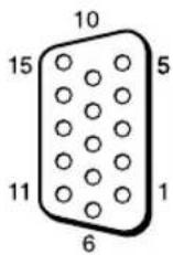
| Pin No. Signal | |
| 1 Red video or C | _R/P_R |
| 2 Green video or Y | |
| 3 Blue video or C | _B/P_B |
| 4 Ground | |
| 5 Ground | |
| 6 Red ground | |
| 7 Green ground | |
| 8 Blue ground | |
| 9 | N o t |
| 10 Ground | |
| 11 Ground | |
| 12 SDA | |
| 13 H sync, Composite sync or Composite Video (as sync signal) | |
| 14 V sync | |
| 15 SCL | |
Note
When inputting a component signal, be sure not to input sync signals to pins 13 and 14. If you do so, the picture may not be displayed properly.
Index
Numerics
4:3 15, 28
A
AC IN socket 11, 19
Active Picture 26
Address 37
Adjust Screen 21, 28, 29
Advanced 38
Advanced Setup 21, 30
Advertisement 38
All Reset 21, 33
Aspect 21, 28, 29
AUDIO connector 11
AUDIO IN connector 12
Auto Adjustment 29
Auto Screen Adjust 31
Auto Shut Off 31
B
Backlight 22, 24
Balance 23, 25
Bass 23, 25
Brightness 22, 24
C
Cable holder 20
Chroma 22
CineMotion 22
Clock Display 30
Clock Set 30
Color System 32
Color Temp. 22, 24
Conference 22, 24
Configure screen 36
Contrast 22, 24
Contrast button 14
Control Mode 30
Control screen 36
Control Setting 30
Custom 22, 24
D
DISPLAY button 14
DVI button 13
DVI connector 12
DVI IN connector 12
Dynamic 23, 25
Dynamic Picture 22
E
ECO Mode 21, 30
ENTER button 11
Error Report 37
F
Full 1/Full 2 15, 29
Full 15, 28
G
Gamma Correct. 22, 24
H
H Shift 28, 29
H Size 28, 29
HD15 (RGB/COMPONENT)
connector 12
HD15 (RGB/COMPONENT) IN/
OUT connector 12
HD15 button 14
|
ID MODE buttons 14, 17
ID Talk 38
Index Number 14, 17, 30
Information 21, 33
Information screen 36
INPUT button 11
Input signal 41
IP Address Setup 32
L
Language 21, 30
LED 27
Logo 32
M
Mail Account 37
Mail Report 37
Main power switch 11
MENU button 13
Multi Display 21, 27, 29
Muting button 14
N
Network 37
Network Port 32
Noise Reduction 22
0
On/Off Timer 30
On-Screen Logo 32
OPTION 1 button 14
OPTION slot 12
Output Format 27
Overscan 31
Owner Information 37
P
PAP 26
PAP button 14, 16
PAP Setting 16, 21, 26, 29
Password 37
Phase 22, 29
PICTURE button 13
Picture Mode Adjust. 21, 22, 24
Picture Mode 21, 22, 24
Picture Position 26
Picture Size 26
Picture/Sound Settings 21, 22
Pitch 29
Position 27
POWER ON switch 13
POWER switch 11
Power/Stand by Indicator 9
R
Real 15, 29
REMOTE connector 11
Remote control sensor 9
Reset 23, 25, 28, 29
RETURN button 11
RGB/YUV 32
s
S VIDEO button 13
S VIDEO IN connector 12
Screen Settings 21, 26
Setup screen 37
Setup Settings 21, 30
Sharpness 22
SNMP 38
Sony logo 9, 32
Sound Mode Adjust. 21, 23, 25
Sound Mode 21, 23, 25
Speaker Out 21, 30
SPEAKER socket 11
Speed Setup 32
Standard 22, 23, 24, 25
STANDBY button 14
Status Display 21, 30
Status Report 37
Surround 23, 25
Swap 26
Sync Mode 31
T
TC Control 22, 24
Tiles 27
Timer Setting 21, 30
Treble 23, 25
True Color Control 23, 24
V
V Shift 28, 29
V Size 29
VIDEO button 13
VIDEO IN/OUT connector 12
Vivid 22, 24
Volume button 14
W
Wide Mode 15
Wide Mode button 13, 15
Wide Zoom 15, 28
Window 27
Z
Zoom 15, 28
AVERTISSEMENT
natural_image
Symbol of a trash bin crossed with a diagonal line and a horizontal bar below (no text or labels)⑨ Touches ID MODE (ON/0-9/SET/C/OFF)
natural_image
Diagram showing a rectangular block with five circular holes and an arrow pointing downward (no text or symbols)Grand zoom
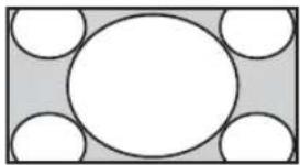
natural_image
Simple geometric diagram with a central circle surrounded by five smaller circles, no text or symbols present.Zoom
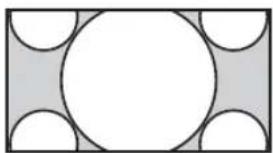
natural_image
Geometric diagram with a central circle surrounded by smaller semicircles and arcs, no text or symbols present.Plein écran
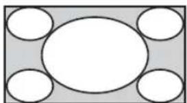
natural_image
Simple geometric diagram with a central oval and four surrounding circles, no text or symbols present.4:3
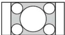
natural_image
Geometric diagram with a central circle surrounded by four smaller circles, no text or symbols present.natural_image
Diagram showing two rectangular blocks with circles inside, one black and one gray, both with a downward arrow indicating transformation (no text or symbols)Grand zoom
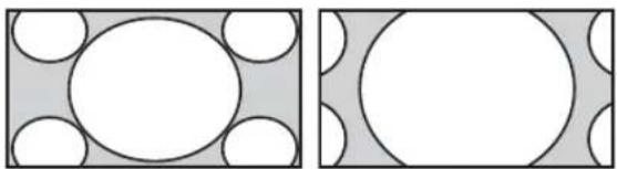
natural_image
Two abstract geometric diagrams with circles and shaded regions, no text or symbols presentZoom
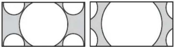
natural_image
Two abstract geometric patterns: one with white circles on a gray background, the other with white circles on a gray background (no text or symbols)Plein écran
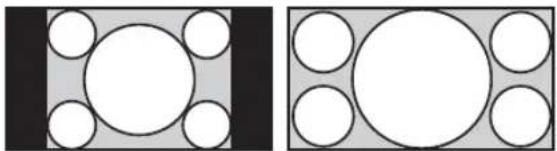
natural_image
Two geometric diagrams showing circles inside rectangles, one with a central circle and the other with a large circle (no text or symbols)4:3
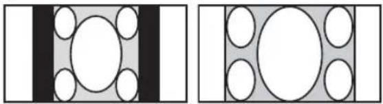
natural_image
Two abstract geometric diagrams with circles and rectangles, no text or symbols presentnatural_image
Simple geometric diagram with a square containing a central circle and four surrounding circles (no text or symbols)Plein
écran 1
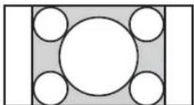
natural_image
Geometric diagram with a central circle surrounded by four smaller circles, enclosed in a rectangle (no text or symbols)Plein
écran 2
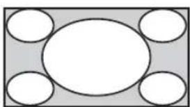
natural_image
Simple diagram with a central oval and four surrounding circles, no text or symbols present.Remarque
Adaptateur STREAMING RECIVER BKM-FW50
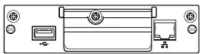
natural_image
Front view diagram of a computer monitor with ports and control buttons (no text or symbols)natural_image
Diagram of a computer interface showing front panel, internal socket, and rear panel (no text or symbols)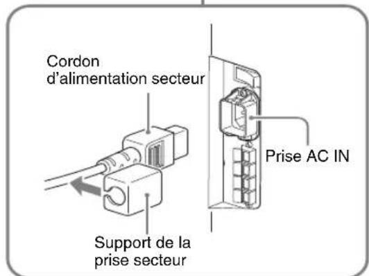
natural_image
Pure mechanical assembly diagram showing a shaft and housing with no text or symbolsBoutons Chrominance (Saturation) +/-
(c-UL), FCC Class B, IC Class B,
EN 60950-1 (NEMKO), CE, C-Tick
Affichage multiple 19, 25, 27
Correct. gamma 20, 22
D
Dynamique 21, 23
E
Échanger 24
Éclatant 20, 22
Emplacement OPTION 10
Réglage mode image 19, 20, 22
Réglage mode son 19, 21, 23
Réglage PAP 14, 19, 24, 27
Réinitialiser 21, 23, 26, 27
Standard 20, 21, 22, 23
Standard couleur 30
True Color Control 20, 21, 22, 23
Tuiles 25
natural_image
Symbol of a trash bin crossed with no text or numbers, representing waste sorting or disposal (no text present)⑨Tasten ID MODE (ON/0-9/SET/C/OFF)
natural_image
Diagram showing a rectangular block with five circular holes and a central circle, with a downward arrow indicating direction (no text or symbols)Wide-Zoom
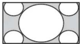
natural_image
Simple geometric diagram with a central circle surrounded by four smaller circles, no text or symbols present.Zoom
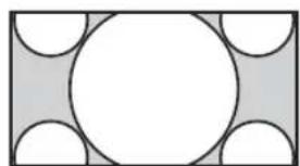
natural_image
Geometric diagram with a central circle surrounded by smaller semicircles and rectangles (no text or symbols)Voll
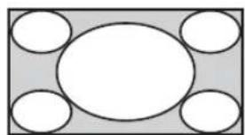
natural_image
Simple geometric diagram with a central oval and four surrounding circles (no text or symbols)4:3
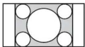
natural_image
Simple geometric diagram with a central circle surrounded by four smaller circles, no text or symbols present.natural_image
Diagram showing two rectangular blocks with circles inside, one black and one gray, both before and after a downward arrow (no text or symbols)Wide-Zoom
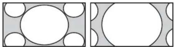
natural_image
Two geometric diagrams showing circles and rectangles with shaded regions, no text or symbols present.Zoom
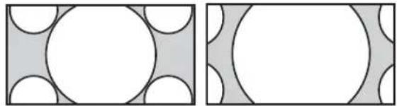
natural_image
Two abstract geometric patterns: one with white circles on a gray background, the other with white circles on a gray background (no text or symbols)Voll
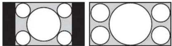
natural_image
Two geometric diagrams showing circles arranged in a grid, one with black borders and the other with gray borders (no text or symbols)4:3
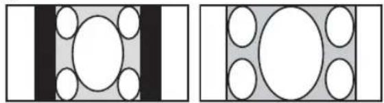
natural_image
Two abstract geometric diagrams with circles and rectangles, no text or symbols presentnatural_image
Simple geometric diagram with a central circle surrounded by four smaller circles, enclosed in a square frame (no text or symbols)Voll 1
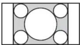
natural_image
Simple geometric diagram with a central circle surrounded by five smaller circles, no text or symbols present.Voll 2
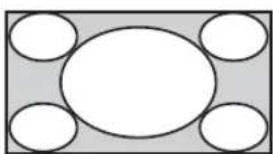
natural_image
Simple diagram with a central oval and four surrounding circles, no text or symbols present.Hinweis
natural_image
Front view diagram of a printer front panel with ports and indicator lights (no text or symbols)natural_image
Diagram of a computer interface showing front panel, internal card slot, and rear panel (no text or symbols)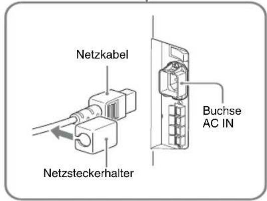
natural_image
Pure mechanical assembly diagram showing a pipe connection with a valve (no text or symbols)natural_image
Technical diagram of an electronic device rear panel with internal circuitry and connectors (no text or labels)①
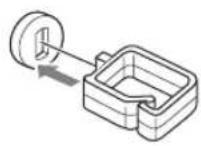

②
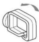

③
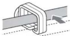
d) VESA Coordinated Video Timing
Hinweise
Mini-DIN, 4-polig (× 1)
Y (Luminanz): 1 Vp-p ±2 dB, sync-negativ, 75-Ohm-Abschlusswiderstand
C-Signal (Chrominanz): Burst 0,286 Vp-p ± 2 dB (NTSC), 75-Ohm-Abschlusswiderstand Burst, 0,3 Vp-p ± 2 dB (PAL), 75-Ohm-Abschlusswiderstand
VIDEO IN BNC (× 1)
Multi-Display 19, 25, 27
N
Password (Kennwort) 35
Phase 20, 27
PICTURE, Taste 11
Pitch 27
Position 25
POWER ON, Schalter 11
POWER, Schalter 9
R
Raumklang 21, 23
Rauschvermind. 20
REMOTE, Anschluss 9
RETURN, Taste 9
RGB/YUV 30
s
Standard 20, 21, 22, 23
STANDBY, Taste 12
True Color Control 21, 22
U
Uhr einstellen 28
Uhrzeitanzeige 28
V
V. Größe 27
V. Position 26, 27
VIDEO IN/OUT, Anschluss 10
VIDEO, Taste 11
Voll 1/Voll 2 13, 27
Voll 13, 26
W
natural_image
Symbol of a trash bin crossed with a diagonal line and a horizontal bar below (no text or labels)⑨Botones ID MODE (ON/0-9/SET/C/OFF)
natural_image
Diagram showing a rectangular block with five circular holes and a central circle, with a downward arrow indicating direction (no text or symbols)Accerc. panorám.
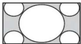
natural_image
Simple geometric diagram with a central circle surrounded by four smaller circles, no text or symbols present.Acercami- ento
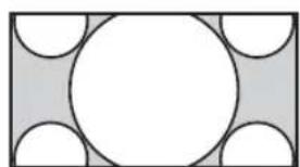
natural_image
Geometric diagram with a central circle surrounded by smaller semicircles and rectangles (no text or symbols)Completa
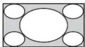
natural_image
Simple geometric diagram with five white circles arranged around a central oval (no text or symbols)4:3
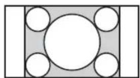
natural_image
Simple geometric diagram with a central circle surrounded by four smaller circles, no text or symbols present.Fuente original 16:9
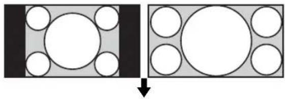
natural_image
Diagram showing a transformation from a square block with circles to a rectangle with circles, indicating a geometric or physical change (no text or symbols present)Acerc. panorám.

natural_image
Two geometric diagrams showing circles within rectangles, one with a central circle and the other with an oval (no text or symbols)Acercamiento
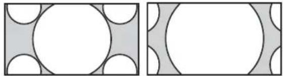
natural_image
Two abstract geometric patterns: one with white circles on a gray background, the other with white circles on a gray background (no text or symbols)Completa

natural_image
Two geometric diagrams showing circles arranged in a grid, one with black borders and the other with gray borders (no text or symbols)4:3
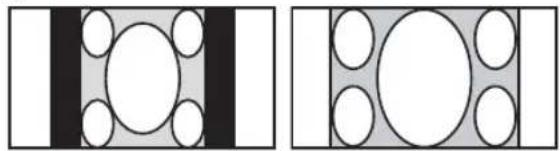
natural_image
Two abstract geometric diagrams with circles and rectangles, no text or symbols presentnatural_image
Simple geometric diagram with a central circle surrounded by four smaller circles, enclosed in a square frame (no text or symbols)Completa 1
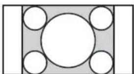
natural_image
Simple geometric diagram with a central circle surrounded by four smaller circles, no text or symbols present.Completa 2
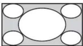
natural_image
Simple diagram with a central oval and four surrounding empty circles arranged in a symmetrical pattern (no text or symbols)Nota
text_image
3 2 1 AUDIO VD HD PcPcVb PcPcVb YiG COMPONENT/RGS INPUT ADAPTERnatural_image
Front view of a computer monitor with ports and indicator lights (no text or symbols visible)natural_image
Diagram of a computer interface showing front panel, internal card slot, and rear panel (no text or symbols)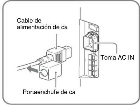
text_image
Cable de alimentación de ca Portaenchufe de ca Toma AC INnatural_image
Technical line drawing of a mechanical assembly with a shaft and housing (no text or symbols)text_image
Technical diagram showing three-step assembly of a server rack with labeled components and directional arrows indicating connection steps.Uso de los ajustes
1.081,6×675,3×275 mm
Ajuste de PAP 14, 19, 24, 27
Restablecer 21, 23, 26, 27
Restablecer todo 19, 31
RGB/YUV 30
s
Salida altavoz 19, 28
True Color Control 20, 21, 22
V
Ventana 25
Vívido 20, 22
AVVERTENZA
natural_image
Symbol of a trash bin crossed with a diagonal line, representing no waste or discharge (no text or labels)
text_image
Diagram of a monitor with labeled buttons and control panel, showing screen layout and function iconsParti Descrizione
⑨Tasti ID MODE (ON/0-9/SET/C/OFF)
natural_image
Diagram showing a rectangular block with six circular holes and a downward arrow, no text or symbols present.Zoom largo
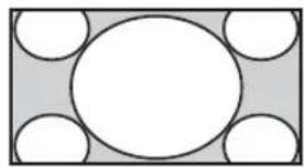
natural_image
Simple geometric diagram with a central circle surrounded by four smaller circles, no text or symbols present.Zoom
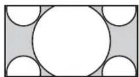
natural_image
Geometric diagram with a central circle surrounded by smaller semicircles and rectangles (no text or symbols)Pieno
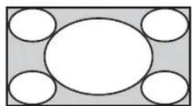
natural_image
Simple geometric diagram with a central circle surrounded by five smaller circles, no text or symbols present.4:3
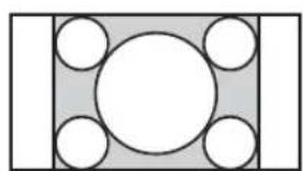
natural_image
Simple geometric diagram with a central circle surrounded by six smaller circles, no text or symbols present.natural_image
Diagram showing two rectangular blocks with circles inside, one black and one gray, both before and after a downward arrow (no text or symbols)Zoom largo
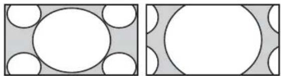
natural_image
Two geometric diagrams showing circles within rectangles, one with a white inner circle and the other with a large oval inside (no text or symbols)Zoom

natural_image
Two abstract geometric patterns: one with white circles and black outlines, the other with white circles and gray curved shapes (no text or symbols)Pieno
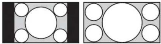
natural_image
Two geometric diagrams showing circles arranged in a grid, one with black borders and the other with gray borders (no text or symbols)4:3
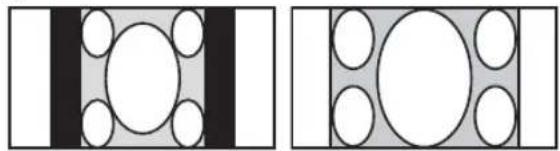
natural_image
Two abstract geometric diagrams with circles and rectangles, no text or symbols presentnatural_image
Simple geometric diagram with a central circle surrounded by four smaller circles, enclosed in a square frame (no text or symbols)Pieno 1
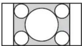
natural_image
Simple geometric diagram with a central circle surrounded by five smaller circles, enclosed in a rectangle (no text or symbols)Pieno 2

natural_image
Simple diagram with a central oval and four surrounding empty circles, no text or symbols present.Nota
natural_image
Pure diagram of a printer front panel with control buttons and indicator lights (no text or symbols)natural_image
Diagram of a computer RAM module showing front panel, internal socket, and rear panel (no text or symbols)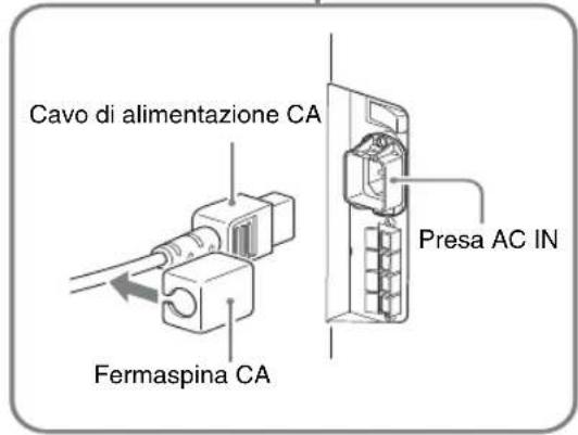
natural_image
Technical line drawing of a mechanical assembly with no visible text or symbolstext_image
Technical diagram showing three-step assembly of a device rear panel with labeled components and directional arrows indicating assembly steps.text_image
Scan di base BC DE FGH FGH FGH A FGH BC DEAdvanced (Impost. avanzate)
1.081,6×675,3×275 mm
UL 60950-1, CSA No. 60950-1-03 (c-UL), FCC Class B, IC Class B, EN 60950-1 (NEMKO), CE, C-Tick
Display multiplo 19, 25, 27
Display ora 28
E
Mail Report (Report posta
elettronica) 35
Mattonelle 25
Modo ampio 13
Modo audio 19, 21, 23
Modo controllo 28
Modo ECO 19, 28
Ripristina 21, 23, 26, 27
Standard 20, 21, 22, 23
Standard colore 30
True Color Control 21, 22, 23
U
⑨ ID MODE (ON/0-9/SET/C/OFF) 按钮
flowchart
graph TD
    A["Hand Press"] --> B["Input"]
    B --> C["Aspect: Wide Zoom"]
    B --> D["Aspect: Zoom"]
    B --> E["Aspect: Full"]
    B --> F["Aspect: 4-3"]
    C --> G["Output"]
    D --> G
    E --> G
    F --> G
natural_image
Simple geometric diagram with a central circle surrounded by five smaller circles, no text or symbols present.↓
Wide Zoom

natural_image
Simple geometric diagram with a central circle surrounded by four smaller circles, no text or symbols present.Zoom
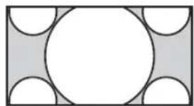
natural_image
Geometric diagram with a central circle surrounded by smaller semicircles and rectangles (no text or symbols)Full
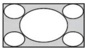
natural_image
Simple geometric diagram with a central oval and four surrounding circles, no text or symbols present.4:3
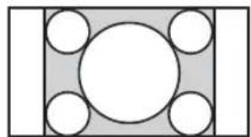
natural_image
Simple geometric diagram with a central circle surrounded by four smaller circles, no text or symbols present.16:9 原始源

natural_image
Diagram showing two states of a transformation: left panel with circles inside a rectangle, right panel with circles inside a larger rectangle, both without any text or symbols.Wide Zoom
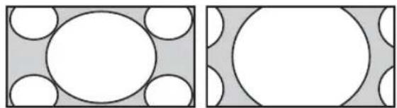
natural_image
Two geometric diagrams showing circles within rectangles, no text or symbols presentZoom
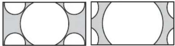
natural_image
Two abstract geometric patterns: one with white circles on a gray background, the other with white circles on a gray background (no text or symbols)Full
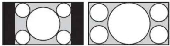
natural_image
Two geometric diagrams showing circles inside rectangles, no text or symbols present4:3
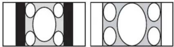
natural_image
Two abstract geometric diagrams with circles and rectangles, no text or symbols present对于个人电脑输入
natural_image
Simple geometric diagram with a central circle surrounded by four smaller circles, enclosed in a square frame (no text or symbols)Full 1
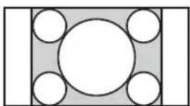
natural_image
Simple geometric diagram with a central circle surrounded by five smaller circles, no text or symbols present.Full 2
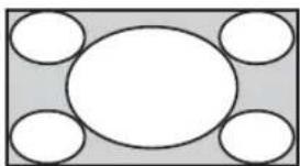
natural_image
Simple diagram with a central oval and four surrounding circles, no text or symbols present.注
natural_image
Front view of a computer monitor with ports and a paper feedbox (no text or symbols visible)此适配器能让您将此显示器用于数字信号。
natural_image
Technical diagram of an internal electronic device with labeled ports and wiring (no readable text or symbols)①
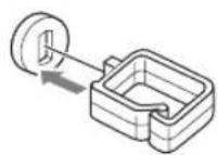
②

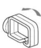
③

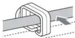
使用设定
菜单综述
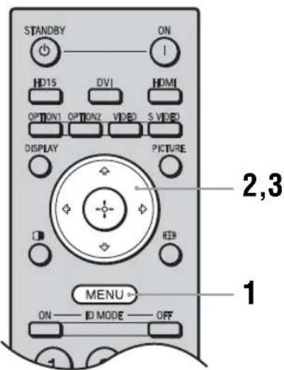
text_image
STANDBY ON HD15 DVI HDMI OPTION1 OPTION2 VIDEO S VIDEO DISPLAY PICTURE 2,3 MENU ON — ID MODE — OFF 1这些设定使您可以使用以下功能:
text_image
Picture/Sound Picture Mode: Vivid Picture Mode Adjust. Sound Mode: Dynamic Sound Mode Adjust. Sel: Set Back Exittext_image
Screen PAP Setting Multi Display Aspect: 4:3 Adjust Screen Set: Set Back Exittext_image
Setup Language: English Timer Setting ECO Mode: Off Status Display: On Speaker Out: On Advanced Setup Information All Reset Set: [OK] Set: Back Exit (Next)Language: (第27页)
Timer Setting (第 27 页)
ECO Mode: (第27页)
Status Display: (第 27 页)
Speaker Out: (第 27 页)
Advanced Setup (第 27 页)
Information (第29页)
All Reset (第29页)

Picture/Sound 设定
对于视频输入
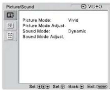
text_image
Picture/Sound Picture Mode: Vivid Picture Mode Adjust. Sound Mode: Dynamic Sound Mode Adjust. Set: Set Back Exit (Menu)text_image
Picture/Sound HD15RGB Picture Mode: Vivid Picture Mode Adjust. Sound Mode: Dynamic Sound Mode Adjust. Set: Back Exittext_image
满屏扫描 BC DE FCH FCH FGH FGH A A BC DE在各个显示器上显示全部信号。
"Window"
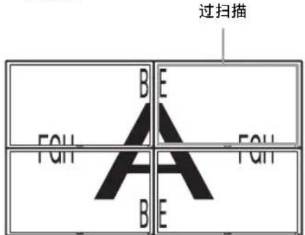
text_image
过扫描 A B E FQH FQH A B Etext_image
Screen PAP Setting Multi Display Aspect: 4:3 Adjust Screen Set: Back Exit:text_image
Setup Language: English Timer Setting ECO Mode: Off Status Display: On Speaker Out: On Advanced Setup Information All Reset Set: Set Back Exit (Enter)若要加亮显示某个选项并更改设定,按 /// 。
按 ⊕确认选择。
“Setup” 设定中包括下列选项:
Requires the use of POP Authentication
before Send e-mail (POP before SMTP) :
IID15 (RGB/COMPONENT) OUT
D-sub 15 芯 (雌) (× 1)
(参见第40页)
AUDIO IN
立体声微型插孔 (× 1)
500 mVrms,高阻抗
DVI DVI IN
(与 DVI 规格版本 1.0 兼容)
AUDIO IN
立体声微型插孔 (× 1)
500 mVrms,高阻抗
SPEAKER 扬声器输出(左/右)
6 欧姆 7W + 7W
基本规格
电源要求
(c-UL), FCC Class B, IC Class
B, EN 60950-1 (NEMKO), CE,
C-Tick
设计和规格若有变更,恕不另行通知。
管脚分配
HD15 RGB/COMPONENT 连接器 (D-sub 15 芯)
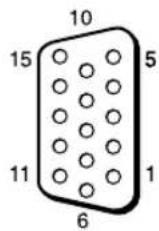
Adjust Screen 18, 25, 26
Advanced 33
Advanced Setup 18, 27
Advertisement 33
All Reset 18, 29
Aspect 18, 25, 26
AUDIO IN 连接器 8,9
AUDIO 连接器 8
Auto Adjustment 26
Auto Screen Adjust 28
Auto Shut Off 28
B
Backlight 19, 21
Balance 20, 22
Bass 20, 22
Brightness 19, 21
C
Chroma 19
CineMotion 19
Clock Display 27
Clock Set 27
Color System 29
Color Temp. 19, 21
Conference 19, 21
Configure (配置)画面 32
Contrast 19, 21
Control (控制)画面 32
Control Mode 27
Control Setting 27
Custom 19, 21
D
DISPLAY 按钮 11
DVI IN 连接器 9
DVI 按钮 10
DVI 连接器 9
Dynamic 20, 22
Dynamic Picture 19
电缆夹 17
电源 / 待机指示灯6
电源开关8
对比度按钮 11
E
ECO Mode 18, 27
Error Report 33
F
Full 1/Full 2 12, 26
Full 12, 25
返回按钮 8
G
Gamma Correct. 19, 21
H
H Shift 25, 26
II Size 25, 26
HD15 (RGB/COMPONENT) IN/OUT
连接器 9
Multi Display 18, 24, 26
N
Network Port 29
Network (网络) 33
Noise Reduction 19
0
On/Off Timer 27
On-Screen Logo 29
OPTION 1 按钮 11
OPTION 插槽 9
Output Format 24
Overscan 28
PAP Setting 13, 18, 23, 26
PAP 按钮11, 13
Password 33
Phase 19, 26
Picture Mode 21
Picture Mode Adjust. 18, 19, 21
Picture Mode 18, 19, 21
Picture Position 23
Picture Size 23
Picture/Sound 设定 18, 19
PICTURE 按钮 10
Pitch 26
Position 24
POWER ON 开关 10
R
Real 12, 26
REMOTE 连接器 8
Reset 20, 22, 25, 26
RGB/YUV 29
S
S VIDEO IN 连接器 8
S VIDEO 按钮 10
Screen 设定 18, 23
Setup (设置)画面 33
Setup 设定 18, 27
Sharpness 19
SNMP 34
Sony 标识6,29
Sound Mode 22
Sound Mode Adjust. 18, 20, 22
Sound Mode 18, 20, 22
Speaker Out 18, 27
SPEAKER 插座 8
Speed Setup 29
Standard 19, 20, 21, 22
STANDBY 按钮 11
Status Display 18, 27
Status Report 33
Surround 20, 22
Swap 23
Sync Mode 28
输入信号 37
索引编号 11, 14, 27
T
TC Control 19, 21
Tiles 24
Timer Setting 18, 27
Treble 20, 22
True Color Control 19, 20, 21
V
V Shift 25, 26
V Size 26
VIDEO IN/OUT 连接器 8
VIDEO 按钮 10
Vivid 19, 21
W
Wide Zoom 12, 25
Window 24
Y
遥控传感器 6
音量按钮 11
Z
Zoom 12, 25
执行按钮 8
总电源开关 8