
RMB1504 - Receiver ROTEL - Free user manual and instructions
Find the device manual for free RMB1504 ROTEL in PDF.
| Product Type | 4-Channel Power Amplifier |
| Brand | Rotel |
| Model | RMB-1504 |
| Output Power | 4 x 70 W (8 ohms, 20-20kHz, <0.03% THD) |
| Input Impedance | 20 kOhms |
| Input Sensitivity | 1 V |
| Gain | 26 dB |
| Frequency Response | 10 Hz - 100 kHz (±1 dB) |
| Signal-to-Noise Ratio | 115 dB (A-weighted) |
| Total Harmonic Distortion | <0.03% (20Hz-20kHz) |
| Damping Factor | >200 (20-20kHz, 8 ohms) |
| Speaker Impedance | 4 ohms minimum |
| Power Supply | 120V/60Hz (US) or 230V/50Hz (Europe) |
| Power Consumption | 300 W (max) |
| Standby Power Consumption | <0.5 W |
| Trigger Input | 12 V (3-30 V DC/AC, 3.5mm jack) |
| Trigger Output | 12 V (3.5mm jack) |
| Audio Inputs | 4 x RCA (2 stereo pairs) |
| Speaker Outputs | 4 pairs of binding posts |
| Protection | Thermal, overload, short circuit; circuit breaker |
| Dimensions (W x H x D) | 431 x 144 x 443 mm |
| Net Weight | 14.9 kg |
| Cleaning | Dry cloth or vacuum cleaner (unplugged) |
| Operating Temperature | Non-tropical climate, free ventilation |
Frequently Asked Questions - RMB1504 ROTEL
User questions about RMB1504 ROTEL
0 question about this device. Answer the ones you know or ask your own.
Ask a new question about this device
Download the instructions for your Receiver in PDF format for free! Find your manual RMB1504 - ROTEL and take your electronic device back in hand. On this page are published all the documents necessary for the use of your device. RMB1504 by ROTEL.
USER MANUAL RMB1504 ROTEL
Four Channel Power Amplifier
Hctpyku npb30BaTeJia
Important Safety Instructions
WARNING: There are no user serviceable parts inside. Refer all servicing to qualified service personnel.
WARNING: To reduce the risk of fire or electric shock, do not expose the unit to moisture or water. Do not expose the unit to dripping or splashing. Do not place objects filled with liquids, such as vases, on the unit. Do not allow foreign objects to get into the enclosure. If the unit is exposed to moisture, or a foreign object gets into the enclosure, immediately disconnect the power cord from the wall. Take the unit to a qualified service person for inspection and necessary repairs.
Read these instructions.
Keep these instructions.
Heed all warnings.
Follow all instructions.
Do not use this apparatus near water.
Clean only with dry cloth.
Do not block any ventilation openings. Install in accordance with the manufacturer's instructions.
Do not install near any heat sources such as radiators, heat registers, stoves, or other apparatus (including amplifiers) that produce heat. Do not defeat the safety purpose of the polarized or grounding-type plug. A polarized plug has two blades with one wider than the other.
A grounding type plug has two blades and a third grounding prong.
The wide blade or the third prong are provided for your safety. If the provided plug does not fit into your outlet, consult an electrician for replacement of the obsolete outlet.
Protect the power cord from being walked on or pinched particularly at plugs, convenience receptacles, and the point where they exit from the apparatus.
Only use attachments/accessories specified by the manufacturer.
Use only with the cart, stand, tripod, bracket, or table specified by the manufacturer, or sold with the apparatus. When a cart is used, use caution when moving the cart/ apparatus combination to avoid injury from tip-over.

Unplug this apparatus during lightning storms or when unused for long periods of time.
Refer all servicing to qualified service personnel. Servicing is required when the apparatus has been damaged in any way, such as power supply cord or plug is damaged, liquid has been spilled or objects have fallen into the apparatus, the apparatus has been exposed to rain or moisture, does not operate normally, or has been dropped.
The apparatus should be used in non-tropical climate.
The ventilation should not be impeded by covering the ventilation openings with items, such as newspapers, table-doths, curtains, etc.
No naked flame sources, such as lighted candles, should be placed on the apparatus.
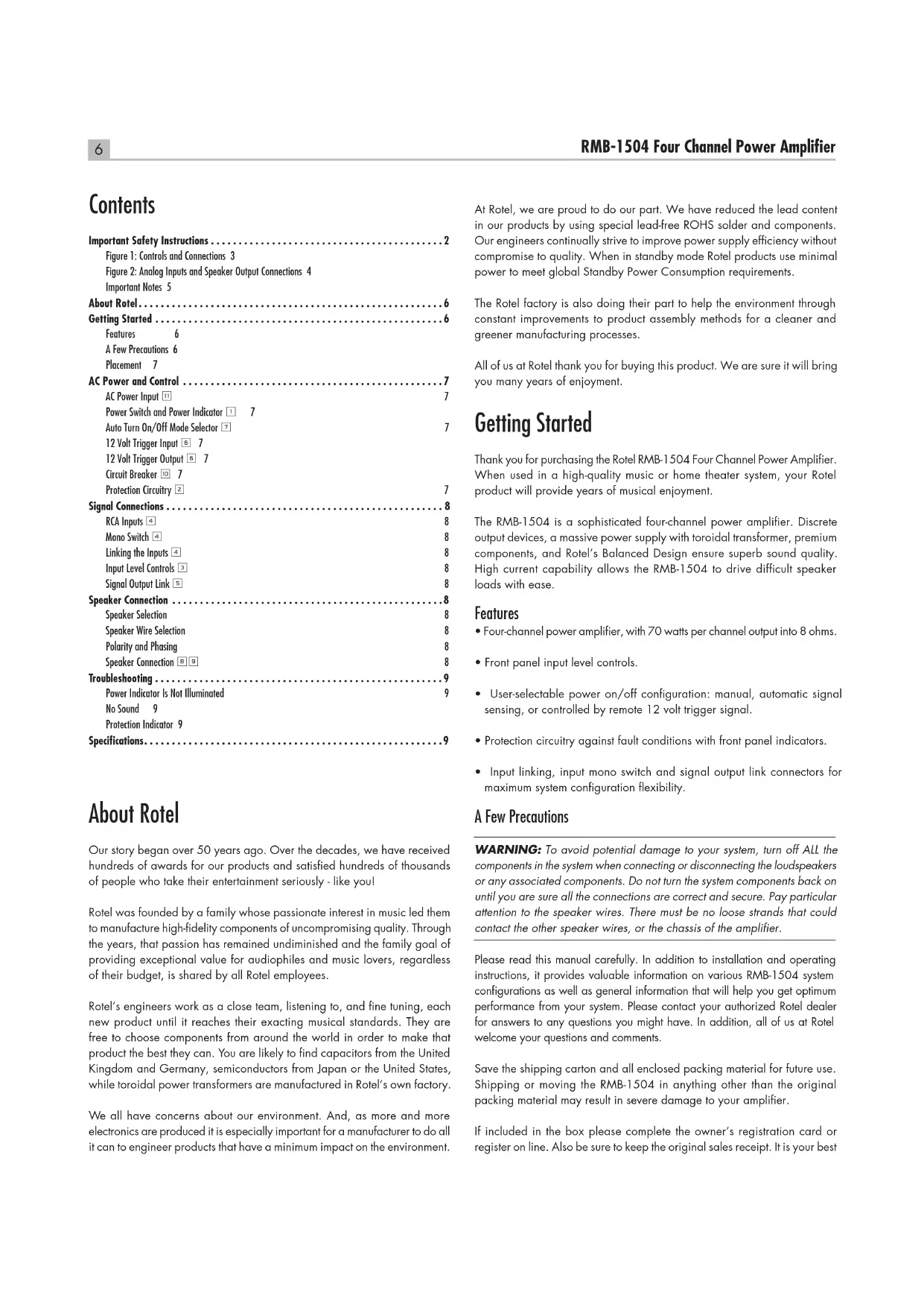
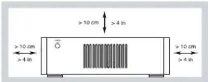
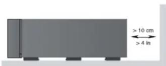
You must allow a minimum 10 cm or 4 inches of unobstructed clearance around the unit.

WARNING: The rear panel power cord connector is the mains power disconnect device. The device must be located in an open area that allows access to the cord connector.
The unit must be connected to a power supply only of the type and voltage specified on the rear panel. (USA: 120 V/60Hz, EC: 230V/50Hz)
Connect the component to the power outlet only with the supplied power supply cable or an exact equivalent. Do not modify the supplied cable. Do not use extension cords.
The mains plug is the disconnect of the unit. In order to completely disconnect the unit from the supply mains, remove the main plug from the unit and the AC power outlet. This is the only way to completely remove mains power from the unit.
Use Class 2 wiring for speaker connections to ensure proper installation and minimize the risk of electrical shock.

CAUTION
RISK OF ELECTRIC SHOCK DO NOT OPEN

WARNING : SHOCK HAZARD-DO NOT OPEN AVIS:RIQSUE DE CHOC ELECTRIQUE-NE PAS OUVRIR
APPLICABLE FOR USA, CANADA OR WHERE APPROVED FOR THE USE
CAUTION: TO PREVENT ELECTRIC SHOCK, MATCH WIDE BLADE OF PLUG TO WIDE SLOT. INSERT FULLY.
ATTENTION:POUR EVITER LES CHOCSE ELECTRIQUES, INTRODUIRE LA LAME LA PLUS LARGE DE LA FICHE DANS LA BORNE CORRESPONDANTE DE LA PRISE ET POUSSER JUSQU AU FOND.
This symbol is to alert the user to the presence of uninsulated dangerous voltages inside the product's enclosure that may constitute a risk of electric shock.

This symbol is to alert the user to important operating and maintenance (service) instructions in this manual and literature accompanying the product.

Rotel products are designed to comply with international directives on the Restriction of Hazardous Substances (RoHS) in electrical and electronic equipment and the disposal of Waste Electrical and Electronic Equipment (WEEE). The crossed wheelee bin symbol indicates compliance and that the products must be appropriately recycled or processed in accordance with these directives.

This symbol means that this unit is double insulated. An earth connection is not required.

Figure 1: RMB-1504 Controls and Connections Commandes et Branchements RMB-1504 RMB-1504 Bedienelemente und Anschlisse Controles y Conexiones de la RMB-1504
RMB-1504 Bedieningselementen en aansluitingen
RMB-1504 Controllie connessioni
RMB-1504: Kontroller och anslutningar
Oprahby npablenia npa3bembl RMB-1504
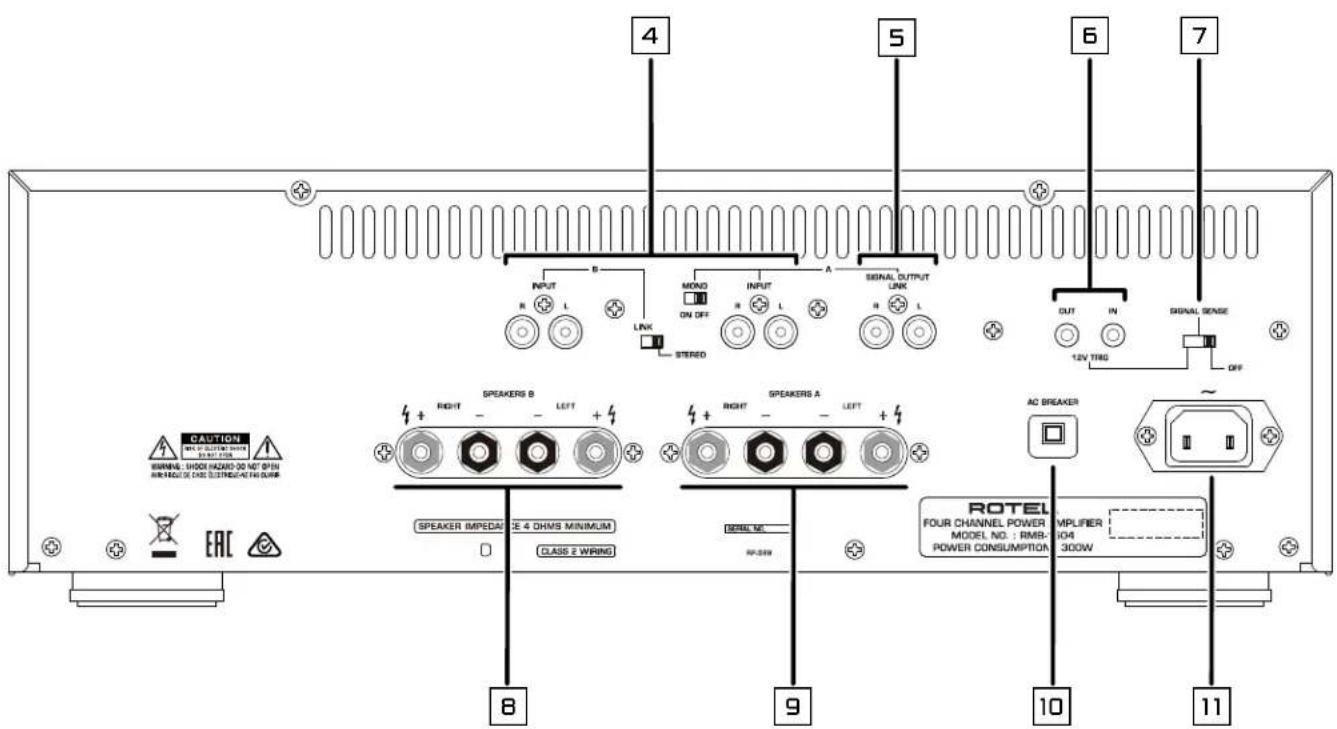
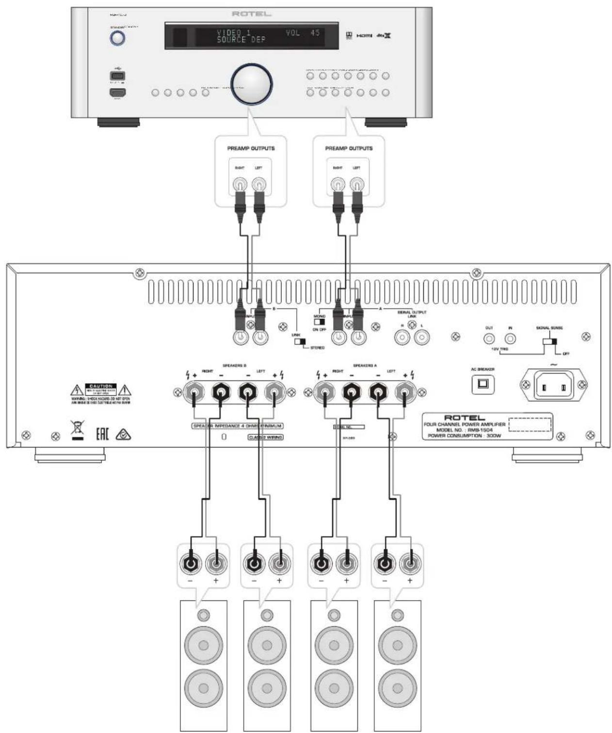
Figure 2: Analog Inputs and Speaker Output Connections Branchements des entrées analogiques et sorties enceintes acoustiques Analoge Eingänge und Anschlieben der Laufsprecher Entradas Analógicas y Conexiones de Salida a las Cajas Acústicas
Analoge ingangen en luidsprekeruitgangen
Collegamenti ingressi analogici ed uscite diffusori
Analoga ingangar och Hogtalaranslutninger
Anajoorobbie BxOdbu N BbIXoDbHa KOIOHKn
Important Notes
When making connections be sure to:
Turn off all the components in the system before hooking up any components, including loudspeakers.
Turn off all components in the system before changing any of the connections to the system.
It is also recommended that you:
Turn the volume control of the amplifier all the way down before the amplifier is turned on or off.
Remarques importantes
Important Safety Instructions 2
Figure 1: Controls and Connections 3
Figure 2: Analog Inputs and Speaker Output Connections 4
Important Notes 5
About Rotel. 6
Getting Started 6
Features 6
A Few Precautions 6
Placement 7
AC Power and Control 7
AC Power Input 7
Power Switch and Power Indicator 7
Auto Turn On/Off Mode Selector 7
12 Volt Trigger Input 7
12 Volt Trigger Output 7
Circuit Breaker 7
Protection Circuitry 2
Signal Connections 8
RCA Inputs 8
Mono Switch 4
Linking the Inputs 4
Input Level Controls 3
Signal Output Link 5
Speaker Connection 8
Speaker Selection 8
Speaker Wire Selection 8
Polarity and Phasing 8
Speaker Connection 8
Troubleshooting 9
Power Indicator Is Not Illuminated 9
No Sound 9
Protection Indicator 9
Specifications. 9
About Rotel
Our story began over 50 years ago. Over the decades, we have received hundreds of awards for our products and satisfied hundreds of thousands of people who take their entertainment seriously - like you!
Rotel was founded by a family whose passionate interest in music led them to manufacture high-fidelity components of uncompromising quality. Through the years, that passion has remained undiminished and the family goal of providing exceptional value for audiophiles and music lovers, regardless of their budget, is shared by all Rotel employees.
Rotel's engineers work as a close team, listening to, and fine tuning, each new product until it reaches their exacting musical standards. They are free to choose components from around the world in order to make that product the best they can. You are likely to find capacitors from the United Kingdom and Germany, semiconductors from Japan or the United States, while toroidal power transformers are manufactured in Rotel's own factory.
We all have concerns about our environment. And, as more and more electronics are produced it is especially important for a manufacturer to do all it can to engineer products that have a minimum impact on the environment.
At Rotel, we are proud to do our part. We have reduced the lead content in our products by using special lead-free ROHS solder and components. Our engineers continually strive to improve power supply efficiency without compromise to quality. When in standby mode Rotel products use minimal power to meet global Standby Power Consumption requirements.
The Rotel factory is also doing their part to help the environment through constant improvements to product assembly methods for a cleaner and greener manufacturing processes.
All of us at Rotel thank you for buying this product. We are sure it will bring you many years of enjoyment.
Getting Started
Thank you for purchasing the Rotel RMB-1504 Four Channel Power Amplifier. When used in a high-quality music or home theater system, your Rotel product will provide years of musical enjoyment.
The RMB-1504 is a sophisticated four-channel power amplifier. Discrete output devices, a massive power supply with toroidal transformer, premium components, and Rotel's Balanced Design ensure superb sound quality. High current capability allows the RMB-1504 to drive difficult speaker loads with ease.
Features
- Four-channel power amplifier, with 70 watts per channel output into 8 ohms.
- Front panel input level controls.
- User-selectable power on/off configuration: manual, automatic signal sensing, or controlled by remote 12 volt trigger signal.
- Protection circuitry against fault conditions with front panel indicators.
- Input linking, input mono switch and signal output link connectors for maximum system configuration flexibility.
A Few Precautions
WARNING: To avoid potential damage to your system, turn off ALL the components in the system when connecting or disconnecting the loudspeakers or any associated components. Do not turn the system components back on until you are sure all the connections are correct and secure. Pay particular attention to the speaker wires. There must be no loose strands that could contact the other speaker wires, or the chassis of the amplifier.
Please read this manual carefully. In addition to installation and operating instructions, it provides valuable information on various RMB-1504 system configurations as well as general information that will help you get optimum performance from your system. Please contact your authorized Rotel dealer for answers to any questions you might have. In addition, all of us at Rotel welcome your questions and comments.
Save the shipping carton and all enclosed packing material for future use. Shipping or moving the RMB-1504 in anything other than the original packing material may result in severe damage to your amplifier.
If included in the box please complete the owner's registration card or register on line. Also be sure to keep the original sales receipt. It is your best
record of the date of purchase, which you will need in the event warranty service is ever required.
Placement
The RMB-1504 generate heat as part of its normal operation. The heat sinks and ventilation openings in the amplifier are designed to dissipate this heat. The ventilation slots in the top cover must be open. There should be 10cm (4 inches) of clearance around the chassis, and reasonable airflow through the installation location, to prevent the amplifier from overheating.
Remember the weight of the amplifier when you select an installation location. Make sure that the shelf or cabinet can support it. We recommend installing the unit in furniture designed to house audio components. Such furniture is designed to reduce or suppress vibration which can adversely affect sound quality. Ask your authorized Rotel dealer for advice about component furniture and proper installation of audio components.
AC Power and Control
AC Power Input
Your amplifier is configured at the factory for the proper AC voltage in the country where you purchased it, either 120 volts or 230 volts. The AC line configuration is noted on a decal on the back panel.
NOTE: Should you move your amplifier to another country, it may be possible to reconfigure it for use on a different line voltage. Do not attempt to perform this conversion yourself. Opening the enclosure of the amplifier exposes you to dangerous voltages. Consult a qualified service person or the Rotel factory service department for information.
NOTE: Some products are intended for sale in more than one country and as such are supplied with more than one AC cord. Please use only the cord appropriate for your country/region.
Because of its high power rating, the amplifier can draw considerable current. Therefore, it should be plugged directly into a polarized wall outlet using the supplied cable or other high current compatible cable as recommended by your authorized Rotel dealer. Do not use an extension cord. A heavy duty multi-tap power outlet strip may be used if it (and the wall outlet) is rated to handle the current demanded by the amplifier and all the other components connected to it.
Be sure the POWER SWITCH 1 on the front panel of the amplifier is turned off (in the "out" position). Then, connect the supplied power cord to the Power Connector 11 on the rear of the unit and the AC power outlet.
If you are going to be away from home for an extended period of time such as a month-long vacation, it is a sensible precaution to unplug your amplifier (as well as other audio and video components) while you are away.
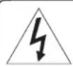
Power Switch and Power Indicator
The power switch is located on the left side of the front panel. To turn the amplifier on, push the switch in. The ring around the switch will light up, indicating that the amplifier is turned on. To turn the amplifier off, push the button again and return it to the "out" position.
NOTE: Place the self adhesive ring over the light surrounding the Power switch if the blue light is too bright.
Auto Turn On/Off Mode Selector
The RMB-1504 provides three different options for manual or automatic power on/off operation. These modes are selectable using a three-position slide switch on the back panel as follows:
- With the switch in the OFF position, the amplifier is turned on or off manually using the front panel power switch. Also use this mode if you are using a switched AC outlet to control power to the amplifier.
- With the switch in the SIGNAL SENSE position, the amplifier turns on automatically when a signal is detected at the inputs. The amplifier will go into standby mode several minutes after a signal is no longer present. The front panel power switch overrides this function. It must be ON for the signal sensing to work. Turning the switch OFF cuts power to the amplifier, regardless of whether or not a signal is present.
- With the switch in the 12V TRIG position, the amplifier is turned on automatically when a 12 volt trigger signal is present at the 12V TRIG input to the left of the switch. The amplifier goes into standby mode if the +12 volt signal is not present. The front panel POWER SWITCH overrides this function. It must be ON for the +12V trigger to work. Turning the switch OFF cuts power to the amplifier, regardless of whether or not a trigger signal is present.
12 Volt Trigger Input
An input jack for connecting the wires carrying a +12 volt trigger signal from a Rotel preamp or surround sound processor to turn the amplifier on and off. To use this feature the adjacent slide switch must be placed to the left position (see previous section).
The TRIGGER INPUT accepts any control signal (AC or DC) ranging from 3 volts to 30 volts. Use a cable with mono 3.5mm mini-plugs on both ends. The +12V DC signal appears at the "tip" connector.
12 Volt Trigger Output
The 12V TRIG jack labeled OUT is used to pass the remote turn-on signal to a second Rotel amplifier. Any 12V Trigger signal at the INPUT jack will be passed through to the OUT jack.
Circuit Breaker
A circuit breaker on the rear panel protects the amplifier's electrical circuit. Generally, the circuit breaker will only open under a fault condition which results in excessive current draw. To reset the circuit breaker, press the button. Should it repeatedly open, contact your authorized Rotel dealer for troubleshooting assistance.
Protection Circuitry
The RMB-1504 feature thermal and over-current protection circuits that protect against potential damage in the event of extreme or faulty operating conditions. Unlike many designs, these protection circuits are independent of the audio signal and have no impact on sonic performance. Instead, the protection circuits monitors the temperature of the output devices and the current they are handling and shuts down the amplifier if operating conditions exceed safe limits.
Most likely, you will never see this protection circuitry in action. However, should a faulty condition arise, the amplifier will stop playing and one or more of the PROTECTION LEDs on the front panel will light.
If this happens, turn the amplifier off, let it cool down for several minutes, and attempt to identify and correct the problem. There are independent
PROTECTION LEDs for each pair of channels which may help in troubleshooting the cause of the problem. When you turn the amplifier back on, the protection circuit will automatically reset and the PROTECTION LEDs should go out, indicating that the amplifier has recovered and the fault corrected.
In most cases, the protection circuitry activates because of a fault condition such as shorted speaker wires, or inadequate ventilation leading to an overheating condition. In very rare cases, highly reactive or extremely low impedance speaker loads could cause the protection circuit to engage.
If the protection circuitry triggers repeatedly and you are unable to isolate and correct the faulty condition, contact your authorized Rotel dealer for assistance in troubleshooting.
Signal Connections
The RMB-1504 has conventional RCA type input connectors, the type found on nearly all audio equipment.
There is also a pair of SIGNAL OUTPUT LINK connections for passing the input signal connected to the "A" pair of channels on to another audio component. Additionally, the input signal to the "A" pair of channels can be automatically linked to the inputs for the "B" channels, so that a separate input signal cable is not required for those channels, for example in large systems where the RMB-1504 is being used to drive multiple pairs of speakers.
NOTE: To prevent loud potentially damaging noises, make sure the amplifier is turned off when you make any changes to the input signal configuration.
RCA Inputs
See Figure 2
There is one RCA input for each of the two pair of amplifier channels. These RCA inputs accept audio signals from preamplifiers or surround sound processors. Use high quality audio interconnect cables for best performance.
For each pair of amplifier channels, connect the left channel output of your preamp to the LEFT INPUT on the RMB-1504. Connect the right channel of your preamp to the RIGHT INPUT. Make sure that the input slide switch to the right of the RCA inputs is in the STEREO position.
Mono Switch 4
When the MONO switch is in the ON position, the "A" left channel input is connected to the right channel.
Linking the Inputs
You can link the inputs for groups "B" to the "A" inputs by placing the input slide switch to the right of the "B" pair of RCA inputs in the LINK position. When linked, no input connection is required for that group. The input signal from the "A" group is sent to the linked pair of channels, allowing you to use all four amplifier channels with the same stereo input signals.
Input Level Controls [3]
Two controls on the front panel, one for each pair of channels, provide input level adjustments. These allow you to adjust the gain of the amplifier to match other components in the system. The A level control changes the gain of the "A" channels; the B level control changes the "B" channels.
To adjust these controls, use a small, flat blade screwdriver. Turn the control clockwise to increase gain. Turn counterclockwise to reduce gain.
Signal Output Link
This pair of RCA connections can be used to pass the unprocessed input signals to another audio component, for example to "daisychain" an additional amplifier to drive a second set of speakers. The input signals connected to the "A" channels is also available at these LINK outputs.
NOTE: These input signals from the "A" channels can also be linked to the "B" inputs by playing the INPUT SELECT switch associated with that pair of channels in the LINK position.
Speaker Connection
The RMB-1504 has two groups of speaker connectors, one for each pair of amplifier channels.
Speaker Selection
We recommend using loudspeakers with a nominal impedance of 4 ohms or higher with the RMB-1504. You should exercise some caution in driving multiple pairs of speakers in parallel configuration, because the effective impedance the amplifier sees is cut in half. For example, when driving two pair of 8 ohm speakers, the amplifier sees a 4 ohm load. When driving multiple speakers in parallel, it is recommended that you select speakers with a nominal impedance of 8 ohms or higher. Speaker impedance ratings are less than precise. In practice, very few loudspeakers will present any problems for the RMB-1504. See your authorized Rotel dealer if you have any questions.
Speaker Wire Selection
Use insulated two-conductor stranded wire to connect the amplifier to the speakers. The size and quality of the wire can have an audible effect on the performance of the system. Standard speaker wire will work, but can result in lower output or diminished bass response, particularly over longer distances. In general, heavier wire will improve the sound. For best performance, you may want to consider special high-quality speaker cables. Your authorized Rotel dealer can help in the selection of cables for your system.
Polarity and Phasing
The polarity, the positive/negative orientation of the connections, for every speaker and amplifier connection must be consistent so all the speakers will be in phase. If the polarity of one connection is reversed, bass output will be very weak and stereo imaging degraded. All wire is marked so you can identify the two conductors. There may be ribs or a stripe on the insulation of one conductor. The wire may have clear insulation with different color conductors (copper and silver). There may be polarity indications printed on the insulation. Identify the positive and negative conductors and be consistent with every speaker and amplifier connection.
Speaker Connections 89
See Figure 2
NOTE: The following text describes both binding post and plug-in connections. DO NOT use both connection methods in combination to connect multiple speakers.
Turn off all the components in the system before connecting the speakers. The RMB-1504 have two color coded connections for each group of amplifier channels, one for the left speaker, the other for the right speaker. Labels above the connectors show the proper connections for connecting speakers. These speaker connectors accept bare wire, connector lugs, or
dual banana type connectors (except in the European Community countries where their use is not permitted).
Route the wire from the amplifier to the speakers. Give yourself enough slack so you can move the components to allow access to the speaker connectors.
If you are using dual banana plugs, connect them to the wires and then plug into the backs of the binding posts. The thumbscrews of the binding posts should be screwed in all the way (clockwise).
If you are using terminal lugs, connect them to the wires. If you are attaching bare wires directly to the binding posts, separate the wire conductors and strip the insulation from the end of each conductor. Be careful not to cut into the wire strands. Unscrew (turn counterclockwise) the binding post. Place the connector lug or wire around the binding post shaft. Turn the binding post clockwise to clamp the connector lug or wire firmly in place.
NOTE: Be sure there are no loose wire strands that could touch adjacent wires or connectors.
For each group of channels, connect the left speaker to the pair of speaker connectors labeled LEFT. Connect the right speaker to the speaker connectors labeled RIGHT. Follow the labels printed above the connectors, Make sure that the positive terminal of the speaker is connected to the + terminal on the amplifier. Make sure that the negative terminal of the speaker is connected to the - terminal of the amplifier.
Troubleshooting
Most difficulties in audio systems are the result of incorrect connections, or improper control settings. If you encounter problems, isolate the area of the difficulty, check the control settings, determine the cause of the fault and make the necessary changes. If you are unable to get sound from the amplifier, refer to the suggestions for the following conditions:
Power Indicator Is Not Illuminated
No main power to the RMB-1504. Check AC power connections at the amplifier and the AC outlet. Check the front panel power switch. Make sure that it is set to the ON position. If using signal sensing auto power-on, make sure that a signal is present at the inputs. If using 12V trigger power-on, make sure that a trigger signal is present at rear panel 12V TRIG IN connector.
No Sound
If the amp is getting AC power, but is producing no sound, check the Protection indicator on the front panel. If it is illuminated, see below. If not, check all of your connections and control settings on associated components.
Protection Indicator
The front panel PROTECTION INDICATORS light when the RMB-1504 protection circuits have shut off the amplifier. Typically, this occurs only when the ventilation openings are blocked, when there is faulty speaker wiring, or after a period of extreme use. Turn off the system and wait for the amp to cool. Then push the front panel power switch in and out to reset the protection devices. If the problem is not corrected or reoccurs, there is a problem with the system or the amplifier itself.
Specifications
Continuous Power Output 4 x 70 watts/channel,
(20-20kHz, < 0.03%, 8 ohms) All channels dirven
Total Harmonic Distortion (20Hz-20kHz, 8 ohms)
Continuous rated power: < 0.03%
One-half rated power: < 0.03%
1 watt power: < 0.03%
Intermodulation Distortion (60Hz:7kHz,4:1) < 0.03%
Damping Factor (20-20kHz, 8 ohms) >200
Input Impedance/Sensitivity 20k Ohms/1.0 volt
Gain 26 dB
Input Overload Level 5.0 volt
Frequency Response (±1dB) 10 Hz - 100k Hz
Signal to Noise Ratio (IHFA) 115 dB
Crosstalk/Separation >50 dB
Speaker Impedance 4 ohms minimum
Auto Turn On Level (with all inputs) 4 mV input signal
Power Requirements
U.S. version
European version 230 Volts, 50Hz
Power Consumption 300 Watts
Standby Power Consumption
Signal Sense
Standby:
1 Watt
<0.5 watts
810BTU/h
BTU
Dimensions (W× H× D)
Front Panel Height
Weight (net)
431× 144× 443mm
17× 5^2 / 3× 17^1 / 2 ins.
3U/132.6mm/5²/9ins
14.9 kg / 32.8 lbs.
Rotel and the Rotel HiFi logo are registered trademarks of The Rotel Co, Ltd., Tokyo, Japan.
Signal Output Link 19
La TRIGGER INPUT accepts a control signal for the current to be changed. The signal is then used to determine the current value of the current in the current state. The signal is then used to determine the current value of the current in the current state.
Baxkhble nHctpyKuIN no 6e3oNaChOCTn
PNEOCTEPEXHEINE: Bnytpn Het qacte, doctynhbx dna o6cnykubnna nonb3oBeTIO. DObepbTe 06cnykubnne KBaHmNpOBaHHOMy MaCtepy.
IPEIOCTEPEXHEHNE:INnCHIXEHNOnaNCHOTB03ROPAHNn INnnpaOHEN3eKTPuueckHM TOKOM He nOBeBprAte DaHnhbI annapat BO3dEChTBNo DOxJr nn BnAri. He DonyckaTe NOANAHN NOcTOPOHNHX npEDMETOB BHytpb KpOpyCA. EcnBHytpb Kopnyca NOANA BNara NnocToPOHNn npEDMe, HemeDNeHNO BbHbTe Bwnky Uhpya NHTAHNn 13 pO3eTKn. IOCTABBe ANnapAT KKBAMDnUppOBAHM CyneMaNNCTy dNOCMOtPa HBO3MOKHORo PemHOA.
IpoaHTaTe Bce HcHCTpyKuHH.
CoxpaHHTe3To pykoBOJCTBO.
06paataBbHMaHaHe Na BcpeDynpKdEHH.
Cnedyte Bcem HcHtpyKUHM no KcNpyatauH.
HeKnOJIb3yIte DaHHOe YcTPOJcTBO B6JIb3N BoDbl.
OuHauTe KOpNc TOnbKO npn NOMoUc cyXo TpAkn Hnn nbIeCOCOM.
He CTabBe yCtpoiCTBO Ha KpObaTb, DMBaH, KOBep HnHa HAnAoTHuNHy NOBepxHOCTb, KOTopAa MOKet PeKePbITb BEHTNlueoHnHbte OTBepTm. EcnY yCtpoiCTBO pa3MeueHcO B KHKnHOM NIn CTeHOM WkaFy, TAM DoNkHa 6bTb BEHTNlueaIa IaI daNOKhoro OXnaJekHnEa.
IepKnte KOMnoHENT B OTdaneHHN OT batapei, KaOpnphepoB, neey mnn IIO60I pyroI annapatypbl, KOtopa npOn3BOoNT TENO.
IOnarH3ObaHbI WTekep IMeET dBa HOxEbx KOnTaKaT, OaHn H3 KOToBbX uHpe DpyrTo. 3a3eMnHOuHII WTekep IMeET dBa HOxEbx KOnTaKA T NptEH 3a3eMnHOuHIO Wtbp. OH o6ecneYbAOT Bauy 6e3oNaChOCTb. He OTKa3bIbAHTcEB CT o MeP 6e3oNaCHOCTn, PnpOCTabNReMbIM 3a3eMnHOuHIM IIN nOnarH3ObaHbIM WTekepom. Ecnn NoctabNReMbI WTekep He NOxOHT K BaAuW Peo3TEK, ObpaTHeCb 3NeKTpnky DJI 3aMeHbY cTapeBWeip o3eTKH.
He npoklaabbaite ceteboi shytp tam, rde OH moKet 6bttb p3a3abneH, nepekat, kpyueh, noDbeprHyt B03eJCTBHO Tena HIN nobpekden KaKMM-N16o CnOc6om. O6paauite oco6oe BHMaHne Ha ceteboi shytp b6n3n tKepa H tam, rde OH BXoHTB 3a3HIO naheIb yctpoiCTBA.
IcnoB3yTeTohko npHaJnEeKHOCTN,yKa3aHHbIe npo3BOUHTeM.
HcnoB3yTeTolbKToTeNekKy,NoCTaBky,ctOky,KpOHTeHHnHnn NOkYCtEMbl,peKOMENOBAHHOH KOMNAHne Rotel.Bybte OTOPOXhbl npn nepemeuehenu yctpoCTBaHaNoDCTABKe NmI CToe BO 36EJAHMe PAHEnOT ONPOKINDBAHN.
CetbeoIshyp CneIyET OTOeHNHbT oCThenHO p03eTKB BVPemrpo3blnHcENyCTpOHTBO 0CTabNeH HeNcIOJIb3yeMbIM dInTeBHpoe BPemr.
HemeJeHNo npkepatne HcNoB3ObaHne KOMnoHeTa n nepeaIte Ha o6cnEobAHnne N/nnn O6CnyKbAHnne KBNMHNPOOBAHNO pEmOHTHoN oPraHHaUNe cENm CetEBOn 1Hyp NnIHTeKeP b6bNnOBpEXd; BNYTpBy cTpoiCTBa yOpHNnnpedMetbNt NPiopNNNnXKnKOctb; YcTpoHCTBO NObBAbnoddoxJDEM;YcTPOICTBO DEMOHCTpyET PnIM3HAKn HENOpMaJIbHO pa60b;YcTPOICTBO yOpHNn NII NIOBpeDNn IIObIM DpyTMnCnO6om.
YCTPOHCTBO CNEyET HCNIOB3OBAb BHTPOINHueCKOM KINMAte.
He cneyet npenTCTBOBATb BEHTNIAUH,3aKpbIbA BENTNIAUHbIEOTBepCTNAkHMNPeDMTaM,KaKra3ETbl, CKATEPH,HTOPbI NT.Ⅱ
Ha yctpoCTBe He DoJnKHO 6bItb NcToOHKO BtKpblrO orH, TAKNX KAK 3aKxHeHHbe CBEH.
OCTabTe He MeHee 10cm CBO6oHOro npCtpaHCTBa BOKpy annapata dna o6ecneHn HpKnyaHn Bo3yxa.
PNEIOCTEPEXEHNE: CTeB0 pa3bem Ha 3aHnei naHEn npEHa3NaeH dJa 6bIcTporo OTOcoHNHeHn yCTpoKCTBa OTNeKTpueckoi CETN. YCTPOICTBO DOnKHO oecneuBA Tb CboOHDIOCTyn K 3aHnei naHEn, TTObI cTeB0 Ka6en MOKHO 6blO 6bIcTpo BIdepHyTB.
Cetbeoe HanpnaKeHne, K KotOpmy NoDcoeHnAeTcH annapat, DIOJXHO COOTBeCTCBoBaT Tpe6oBHaHmY, yKa3aHbM Ha 3aJHe naneH annapata (CUSA:120B,60Tc,EC230B,50Tc).
IodcoeHnHrTe KOMHOENTKNTHTAOUePo3ETKe TOLbKO npn NOMOu CTeBOr OHypa N3 KOMNIEKTa NOCTaBKN, NIN ero TOOHOr 3KBmABeHTa. He nepeJeBbAte NoCTabReMbI WHyp. He IcNoB3yTe yDnnHntEnIe NcTeBOr NITAHJ.
OchOBHn wTeKepe CTeBOro Whpya ABnIeTcR oTKInouaembIM oT anpapaTda JnnonHOro OTKIOUeHN H3dNnO rNTnAIOuE cETn,OCHOHn wTeKepe CTeBOro KAben cNeJeY eTOcEOHNr bT oCTeBn po3EtKn NepemEHnORo TOKa a TaKke H3dNn. 3To eHNCTBeHnbl CNco6b, YTObbl NINOHeTb y DaJIbHTb CeTeBO nNTAHne Ot H3dNn.
3ToaannapatdoJxhen6bIbnoKlnuOeH KceTeBOpo3EKe C 3aunthbIM 3a3emJIHeHEM.
IcnoB3yIte Ka6eHn C3aunToi Class 2 npnNoCoedHneHH KOHOK K KEmMaM yCUnTeN Ipy o6ecneHn HadeKHOI N0AUNH MNNMN3aun pNcKa yDapa 3NeKTPNCTOBm.

CAUTIONS RISK OF ELECTRIC SHOCK DO NOT OPEN

WARNING : SHOCK HAZARD-DO NOT OPEN AVIS: RISOUE DE CHOC ELECTRIQUE-NE PAS OUVIR
JIIN CSHA,KAHAblnI INDPTNXCTPAH,ΓEYCTPOXTBQ ODOPEPERKNCNOLB3OBAHNI.
CAUTION: TO PREVENT ELECTRIC SHOCK, MATCH WIDE BLADE OF PLUG TO WIDE SLOT. INSERT FULY.
ATTENTION:POUR EVITER LES CHOCSELECTRIQUES, INTRODUIRE LA LAME LA PLUS LARGE DE LA FICHE DANS LA BORNE CORRESPONDANTE DE LA PRISSE ET POUSSER,JUSQU AUFON.
106KsE96pHnE HmNIMB PABHOCTOPHM EN TpeYbIhIKHe NpDyynPekDAeT NOIL3OBaTeH O KBNHNH BHTYPR KOpNYCA3gEDM ENHONIPBOAHHORI HnRPAHHEKN, BENPHINHOC KOTPOPOE MOKoC3BaAIBTOBnACOHOCbPnOAKH8E YHOBKEA NtOKNTHKBCNM TKOM

MoI6pOzKeHHe NCKoJIaTeBnHO 3nAka B
PbABTOChTHeN MTEyPOJINKHe
npDyNJnPcKaDeT nO3b0eTaI O HANHIN C
COPONBOXDAIOuI annapat DOkYMHTaAMU
BAKhIXu HNCTPKuyrO nOcKfYATAaUMi
TEXHNUCKOMY oCNJyHXBAHMO.

IpoNyKtB Rolc npoekTnpobAHb taK, 706bl cootBetCTBOBaTB Tpe6oBAHnM MEkHyapnoDbx DnpeKTHB NO orpaHneHIO pHmHeHH BpehBx BeueCTB B 3NeKtpOTexHHueCKOM NneKTPoHOM 6OpOyOBaHH (Restriction of Hazardous Substances - RoHS), TaKke no oOpaaehnIO cOnyKnHBMM Cboi cPOK3NeKtpOTexHHueCKM HneKTPoHBM oOpOyOBaHHem (Waste Electrical and Electronic Equipment - WEEE). M3o6paxHenne nepeepKhyTO r Mycophoro 6aKaHa Na Koneca X O3NaHauTAKKe To, YTO 3TN POyKtB DoJXHb6BbT BToPHNO hONb3oABHb (peuHKnHPOBaHb) HnN Xe 6op6oTaHb B COoTBETCBM CYONMAHYbIMN BBIe NpeKTHBaMH.

3TOT CHMBON 03Hauaet, YTO yCTpOHTBOMMeET DBOIHyU H3OJIaIIO. 3aEMeIHe He Tpe6yETCA.

Copepkanhe
Pcynok1:OpranbIy npaBneHn npa3bEmbl 3
Pcnyok 2:AhaIorOBeBbBXoDbu BbIXoDbHa KOnOHKn 4
Baxkhbe 3aMeHHa5
Baxkhhe Hnctpykun no 6e0naochtn. 45
OKOMTANHIMROTEL. 46
Iepbte warn 46
PnMmeaHMe:OCHOBHeXe xapakTePmCTHK 46
HeKoTOpbIe MepbI npedocToPoxHoCTn 46
PazmeueHne 47
HHTaHne uypabnene 47
BxOeTHNepemEHnHOToKoA 47
BbIKIOATeINb NITAHM INHIMKATOP NITAHM 47
IpeekHouateInbpeKMAaBOMATMueckoro BkHoueHn/BBkHoueHn 47
+12B TpuRrePbH BxOd 47
+12B TpurnepHbI BbxOa48
YCTPOICTBOOTKIOUeHn4 48
Cxembl 3aunTb1 48
PazbemblnraCnHnOB 48
BxoDbRCA 48
Ipeeknquatelb MONO 48
Coprrnne Bxodob 48
YnpaBHeHn BxOaHbM ypOBHeM 48
OTBETBNEHME BbIXoJHO CmHana 48
IIOcoeHHHeAkyCTuuecknx CNTem. 49
Bb6opKo10Hok 49
Bb6opakcytmeckoro kaebn 49
Ponapnoctb n fo3npobka 49
PnncoeHHeHne akyctmeccknx CnTeM 89
06HApUyKeHHe HcTpaHHe HeHCnPaBHOCTei 49
HnIaKATop nTahnHa nepeDnei naHei He cbETTC 49
HeT3ByKa 49
Hdikatop 3aunTbI 49
Texnueckne xapaKTepeHcTNKn 50
OKompanROTEL
NCTOPH Hauwekomn Hauhanacb noTn 50 nT hazad.3 npowedne DecaTNNEH Mbl NOLyHmN COTHn Harpad 3a HauH npOdyKTb nCdeNaH CactINBBIMCOTHn TBICH LIODe, KOTOpBIE OTHOCATC KCBOM pa3BneHnM BONHe cepbe3HO-TakKe,KaK Bbl!
KomnnaRotel 6bila ochoBaHa cemEChBOM, yBa CTpaTb K My3bke npoDmla cTpeMJIHee co3dAbTa hi-n KomnoHEnTb 6eCKomnpomCCHoro KaueCTBa.3a MHOrne roDbl 3ta CTpactb HnuyTB He ocna6la, n no cei denb 06uae cnb - BByIyckaTb PPOyKtBu NCKJIOHTBeHOB CEHHOCTN DnaydNOOHNIOB NIO6ntene My3bIK, He3aBNCIMO OT INx fHnHaCOBbix BO3MOXHOCTe, pa3dienrTc BCEMI cotpydnkamn Rotel.
HJKeHepBo Rotel pa6oTaIOT kak ednHaKaOMaHa, npocnyuNbBa nTuaTeNbHO doBDA KAKDbHOBHIO pOdyKT DoTAKORO yPOBnCobepHeCTBa, KOrA OH 6ydeTyOBnEeBOPaTbNx CTpOrIM My3bKaIbHbM CTaNapTAM. IMnpedocTabHe cBO6Da Bbl6opa KomJIeKtkyUOnNo BCMeMy Mpy, YTO6bI CDeLaB annapat KaK MOxHO LyUWe. BepoTHO, Bbl CMoxTe HaHTN B HauNX annapaTx OT6OpHbe KOHNcAToPbN3 BeNKo6pTaHmN IN EpMaHmN, NOnynpOboNDnKnN 3raONnn N CiUA, Ondako TopoAnDaJIbHbIe CINOBBe TpaHcΦopMaToPbMb N3rotabNaem HA co6CTBeHHOM 3aBoe ROTEL.
BceMb3a60TmC6oXpAneOkyKaioeIcpebl.No Mepe TOrO,Kak Bce 60JIbSe 3NeKtpoHHbIX yCTpoiCTB BMpe BbyNcyAE, a nocle OKOHuaHn Cpoka CnyKbByBb6paCbBaetc, dIy npOn3BODntela Oco6eHHO BaxHo npKoHCTpyuPobAHn IpOdyKTOB cElaTaB Ce BO3MOxHoe, YTO6bl OHHaHocnn MNHMmaIbHbYuep6 Zemne I NCTOCHNKAM BObl.
MbB KOMnAHm Rotel, ropIMC8 CBOHM BknaDm B 06uee DeIO. Bo-nerbbIX, Mbl cokpatINu COepjxHae CBHua B CBOe3NeKTPOnHKe, 3a CteTNCNoIb3OBAHn npinno, oTBeauoJero Tpe6oBaHnAm ROHS. HaaN INXkeHepb IocToHHc TpeMaTc ynyuWntb K.I.n. 6IOKOB NITaHn, 6e3 yUepe6a Iy KaueCTBa 3ByaHnHa. HaxoRb B pexime OxndAhn staDbY, npOdyKtBi Rotel nCNOJIb3yIOT MNImalbHOe KOInueCTBO 3Heprn, 4TO6bI yOBDIeTbpNTIIO6aJIbHbIM Tpe6oBaHnAm Ha Notpe6JeHne B pexime OxndAhn.
Фбрika Rotel takke BHCNT CBOB KNLAD B ylyuweHne oxpaHbOkpykaHoeCpeIyIyTEMIOCTOHHOROCOBepHECTBOBaHnIpnON3BODCTBeHHbIX npouecCOB,Denaiix BCE 60lee uNCTbIMN I 3eNeHbIMN.
BceMbcoTpduHnK KomnAHn ROTEL, 6NaorOapm Bac 3a nokynk 3Toro mDJIy. MbI yBepeHb, YTO OHO DCtABNT Bam MHORo IET yDOBOJcTBNA.
Первbieшагn
Bnaorapm Bac 3a npno6peTeHne 4-kaHaIbHorO ycInnteMa MoHocTn Rotel RMB-1504. Pnp nCnObl3oBaHHn B BicokokaeCTBeHHo CnCTeMe dIbaBocnpOn3BeDeHnMy3bIKn IIN DOMaHrero KInHOteAtpa, BaWycInnteBROTEL o6ecneHT MHRNE rOdby yDobOBJIcTBnO rIpocnyuBaHn.
RMB-1504AIBIETCnOxHbIM4-KaHaIbHbIMyCmNTenEMMoUHcT.NckpeTHBb BIXOHBIE TpaH3NCTOpbI,COINHbI NCTOCHNKITaNHAICTOPoNDaJIbHBIM TpaHCΦOPMAtopOM,OT6OpHbIE KOMPNeKTKyUQne IN C6aNAHCnPOBaHHa KOnCTpyKcNROTELO6eCNEuBAJTO pBeOCXoHDoe KaecCTBO 3ByaHN. CnocO6HocTB RMB-1504 OTdABaTb 6OBWoTOK NOBnEeMYJeKo CnpabNtBCA《TPydHbIMnHarpykAMB BuDE rPoMKorOBOpTeNei.
ПиMuMeaHHe:ОснOBHbIeХаразКТерпСТИК
- YeTbpeKaHaNbHbYucnnteMbMoOnHocTN,70BtHa KaHa npHarpy3Ke 8OM;
Ha nepeHne naHEnI paCnIOJKeHbI pEryJIaTOpbl BXoJHO yPoBnK, KOtOpBEmoJHO cKOHnHyprpObaT TpeMcNoc6amu;
KoHnIgpyaunBkIoueHn/BybIKIOueHnPiTaHnIO BbIbOpy Nolb3ObaTeHa: pyHoe, abTomatueckoe npn o6hApyeHn CnHana, nctaHNoHHO 12-BoTobBIM NyCKOBbIM CnHAnOM;
-Cxema3aunTbIOTkopOTkoT03aMbKaHnCINHnKaTOpamHa nepeDne naHeu.
Pa3bEmblBxOJHORo COeINHeHH, BxOJHOro MOHOoHoHNueckOro NepeKIOuCaTeIa I BByXODHOrO CnIHnAa IpnMaKcMImlbHOH rN6KcTn KOHfMyrpaunCnCTembl
HeKOTOpBle MePbI npedocToPOxHocTn
IPMMEYAHNE: ymo6b u36examb 803moxHo2o noepxdeHuae uuecumembi, bkioume BCE komnoehmbi cuminp npu nodcoedunhuu uno mdcoedunhuu akymueckux cuminem unu dpyzux cbzahnhbx kcmnoehmOB. He kioaumekomnoehmbi cuminembnoka Hey6dumecb, yoece doedunhure bInonHeBnpabunho uHadeXHO.Oc6oebHumae ydenume konohouhim npoobam. He donxho 6bimb paIoxmaeHHbIX KOHOB, Komopbie.
6bI Kacanbc Dpyrnx npoBodOB nIN KOpnyca ycInnteY. Ioxayncta, IpOHTaTe daHHe PyKOBOCTBO BnIMATEbHO.KpOme OCHOBHX HAcTAbneHmIO yCTAHOBKe INKcNpyatauIN, OHO COpejXNT INHOFopMaUNo O pa3NHybIX KOHfrypaunx CnCTe Ma OHObE RMB-1555/1585 IN o6Une Co6paxeHnO TOM,KaKdoobTcR OTcunnteNt ONTMaNbHorO KaeeCTBa paObTI. IoxaynctA, 6bPaauTeCB K BaWemy ABTopn30BaHOMy dInepy ROTEL 3a OTBeAMn HA IIObBe BOIpocbl, KOToPbe MOrT Bo3HNkHyTb. KpOme TOrO, IIO6oB coTpudNK ROTEL cyOboBCTBnEM pImet BaUn BOnPoCbl IN KOMMeHTapmN.
CoxpaHnTe TpaHcnpTHyO KapToHnyo Kopo6ky ot RMB-1504 n Bce BLOXeHHbIe ynaKOBouHbIe MaTePnAbIy dIaIaNbHeNwero nCNoIb3OBAHn. TpaHCnpTIpOBaHne IIN nepeMeueHne RMB-1504 BnIO6oTape uynakOBke, KpOmeOpunHaBbHO, MoXeT npUBeCTN K cepbeHOMy nobpeXdEHNIO BaWero ycInnten.
Ecnn OHO BkHIOUeBO B KOPo6Ky, NOXaIyIcTa, 3aONHnTe perncTpaIOnHHO kAPTOCKy BnaIeBua IIN 3apERNCTppyIteb OHaIH. CoxpanHe Yek o npodae. OH AIBNETcH HAnLyUWe pRNCtpaIeN DaTb PnO6peTeHn, KOtopa 6ydt BoCTpe6oBaHa B cnyae rapaHTmHorO 06cnyKuBaHn, ecnn OHO KOrda-llbo NoHaO6ntc.
Pa3MeueHne
RMB-1504 Bdydienhotenno npn Hopmalbho pa6ote. Tenootbohdin BeHTnlaonHbte OTBepCTNa BycuNTene CnpoeKtnpoBaHbI daPaccenBaHna 3ToroTeNla.BeHTnlaonHbte npopeBn B bcpxHe KpbiKe KOpnyCa dOnkHb 6bItcBo6oHbI.CneJeTocTabnHe MeHee 10cm Cbo6oHOrO npoctpaHCTBA BOKpy Kopnyca np6opa, a TaKHe HndJexaue Bo3duuHb I nOTOK B MeCe yctahOBKn, YTO6bI ppeDTbATNb Ycunntelb ot neperpeBa.
Kpome toro, nomnnte o Bece daHnoro ycui ntei, korga bblbpaete Me cto 1ra ero yctahOBKn. Y6eHTecb, TTO nonka nn CTennlax Moryt BbldepeXaTbe 0ec EepKaTbe PekomeHnyem nCnoB3ObaTa CneuaanuNipobAHny Me6eB Jnay ayDIO KOMNOHETOB. Takaey Me6eJb paccntaHa NaDabNeHn Bn6paun, OtpuataHBO BnIHO u HauCeTBO 3ByKOBCPON3BeDeHn. O6paTHeCB K BaWemy ABtopu3OBAHHomy Dnnpery Rotel 3a cobetamn no Bb6opy noXoJauey AyDIO Me6eHNu YcTahOBKn KOMNOHETOB Ha Hee.
Iitahne u npablenne
Bxod cetn nepemehnro Toka
Baw ycnntenb hactpoeh Ha 3aBOe B COOTBeTCTBm CO cTaHApTaMn 3neKtpnuecko cetn B Baweien Ctpane (120 nnn 230 B nepemehoro Toka n 60 nnn 50 T). KoHpyaunna 3neKtponntanna o6oHaueHa ha 3adne nnene annapata.
IPIMUEAHHE: Ecnu Bn nepeedeme 6 pzyu cmpany, moxno npucnocumb ycunumelk dpyzomy cemeomy hnpaxheno. Odaako He nbimaumecb cdamb 3mo camu. Omkpblk kopny cuncumen, bbl moxeme nonyumb yap mokom, onachbu dna kuzhu. Obpamumecb K KaanuuppuobahHomy Macmepy unu b cepbuchyo cnky6y Rotel.
IPIMMEYAHNE: HekomopbIe npodykmbI npedHa3Hauenb Ira npodaku 6oee yem B odHou cmpaH e u no3momy nocmaeJomc c Heckonbkumu cemebbmu Ka6eMaMu. NcnoB3yUme monbko mom Ka6eB, Komopbiu nodxodum dna bawese pe2uoha.
I3-3a OTHOCHTBHO BbICOKO BbXODHO MOUHCTN RMB-1504 notpe6niet 3NaHTeBbHbTOKOTcETN. POtOMyERO cneDyET NOKIOuATb HENOCpeCTBENHO Kpo3eKcCPOJIAPIN3OBAHHO CTHKO,NCIOB3yprPnIraemb Ka6eBnn DpyrO CoBMecTUMb C BbICOKM TOKOM Ka6eB, KaK peKOMHeBOAHO BAIMM
ABTOPU3OBAHbIM DnIePOM Rotel. He nIb3yIteCb yDInHHTenAMM. MoKHO NcNoJIb3OBAt PbA3BETBNTebl NTaHnBa BICOKo MOuHOCn,ecN OH (NCTEHNApo3TeKa) cNOcO6hbl BbIepeXaTb CymMaphbl TOK NOTpe6NeHnYcINNTeN I dpyTHN NOkJIIOueHbIX K Hemy UCTPOIcTB.
Y6eDInTeCb, TTO BbKIIIOUaTeIb NITaHIN Ha NepeIHeN NaHEn YcNInTeIa HaxoDInTCB NIOLOKeHN NTOKIOUeHO).3aTEM BOTKNITE OINH KOHeC cTeBOrO 1Hypa B pa3bEm Ha 3aHHeN NaHEn YcNInTeIa. Iocne 3TOrO BCTaBbTe dpyroJ KOHeC cTeBOrO Ka6eJI C BNkO B p03eKy.
Ecnn Bb Haidonro ye3kaete n3 doma, Hanpimep, Ha meca, pa3ymho 6ydet BbHyTb BNIKH HYPOB NHTAHNA YCINNTeN I Dpynx aydno-BnDeo KOMNOHETOB CNTEmbl n3 po3etok.
BbIKIOATeNB NHTAHN INHINKATOP NHTAHN
BbKIOUaTeIb nHTAHnna pacnoLoKeH na nepeHne naHenn yCUNNTeIa. IIN BKIOUeHn yCUNNTeIa (uIN dNRAAKTNBaun KAKOR-nI6o peXmAb ATOMATueckOrO BkIOUeHn), HAXMITE Ha BbKIOUaTeIb. CBeTOnIOHb INIKaTOP BOKpyr BbKIOUaTeIa 3arOpNTc, NOKa3bIBa, YTOUCNIteIb BkIOUeH. 4To6bl BbKIOUHTb yCUNNTeIb, HAXMITE Ha KHOKNy eue paN bEPHInTe ee B NOLOKeHne «BbKIOUeHo.
PIMMEYAHNE: Ecnu ceeuehe cuHezo KOnbueo2o uHdukamopa eokpy 6bIKIOUoyameI NOKAKemcBAM CnUKKOM RPKUM,MOXHO 3aIenumb eO cAMOKJIeUUMC KOJIbUOM.
IpeKIOuOaTeIb peXIMAbOTOMaTuecCKOrOBKIOUeHnB BbIKIOUeHH 7
RMB-1504 o6ecneuBaet npa3nHbix Bo3MOxHocTnI pyHoro nn ABTomatueckoro BkIOUeHn/ BbIKIOUeHn NtAHn. 3TNpeKmbl Bb6upaOTc npn nOoTI pExNo3NIOHOrO DnKKOBOrO nepeKIOUaTeHa 3aHne naHenn:
Korda daHHbI nepeKnIOuATEnb haoDITcB nNOJKeHm OFF,ycnINTeNB KBIIOUaIOT N BbIKIOAUAT BPyHyO npi NMOOUI KNOHKN Ha nepeHne NaHEn. 3TO T pEXKIM TaKke IcNOb3yIte,ecNI BaWpa po3eTKa nepeMeHHoro ToKa ChabKeHa BbIKIOUaTeMe dnynpaBHeHna Ondaue HNTAHHa ycINlTeB;
Korla nepekknouateIb haxoITcB noloxhen SIgNAL SENSE,ycnnteIb BKIOUaETcABTOMaTIueckn npiOBHApyKeHN CnIHana Ha BXOax. YcniNTeIb nepeJET B JxdyuI pexIM uePe3 HeCKoJIbKO MmHT NocLe NcCHe3HOBeHN CnIHana.KhONka HnepeDHeN naHeIN 6IoKpuyET ATy FynKlIIO.OHa DOnjKa 6bITB noloxhen ON,yTO6bl cxema oBHpayKeHN CnIHana pa6oTana. IpekeKnueHne KhONkB noloxhen OFF oTKIOuaET PINTAHne OYcInnteIa, He3aBNCIMO OTTO, pncytCTByet CnHAn nn HET;
Korda nepeknlovatnel haxodntcB noLoxhen 12VTRIG,ycnllntelb BKlouaetcABTOMaTtueckn npn noRbneHm 12-BOIbTOBOro CnHana Ha BxOJe 12VTRIG cIeBa ot nepeknlovatnel.Ycnllntelb nepxoDNTB Kdyuyn pekmm, ecnn 12-BOIbTOBbCnHAnOTcyTCTByet.KhONkaPOWERSWITCHHa nepehdne naHEn 6IokpyET 3Ty fHKUIO.OHa donkna HaxoDttcB noLoxhen ON, uTo6bl 12-BOIbTOBb 3anyckaiooi CnHan pa60an. PekeKnoyehne KhoNkn B noLoxhenE OFF oTKlloaet nItahne OT ycInntela, He3abncmo ot TOro, npncytCTbyet 3anyckaiooi CnHan Hn Het.
+12B TpnrrepnbI BxOa
Bxodhoe rhe3do nI npncoeunneHnKa6e, Hecyero 12- BonbToBbI 3anyckaoiC nIhAn OT npedBaPntbHorO yc nnTeTnRAOTELnn npoueccopa okpykaiooero 3Byka, npdHa3NaeHnoro dN BkIoueHn I BVkIouehn ycnnten. T06bpean3oBaTb 3Ty fynKcUIO, cocEnm
DnBKKOBbI nepeKIOuATEnb DOJIKeH HxOaNTbcra B NeBOM NIOJOKeHN (CM. npdeBdywn pa3den).
3aynckaoiBxODTRIGGINPUTnpHnMaetIIO6oynpabnlooiCnHan (nepemehoro nnnnoctoHHoro ToKa) Bdnaana3Oe 0r 3do 30 BoNt. Ncnonb3yET Ka6eIb cMOHOHNueCKMn 3,5-MM MmHnKeKamn Cobox KOHcOB.CnHan +12 B NoBnEeTcHa KONHKe paBema.
+12B TprrrepHbIy BbIXoD
THe3do, 06o3haeHoe 12VTRIG OUT, nCnoB3yetcInI npOnycKaHnI DCtAnuHOrO CnHaNb BKnIOueHnHa BToPoI yCunInTeIb ROTEL. IIO6o3aynckAioouni CnHan 12Ba BxOHom THe3de 6yJed NpepaHn BaBixOHOe THe3do.
UcTpoCTBOOTKIOUeHnA 10
Cetebn npedoxpahntnb Ha 3aDne nane nn 3aunuae T nektpnuecnck cxmblyucnntenB.Booem cnyae,pa3mbkaTeNB cenn Cp6oatae tonbko npn HncnpabHOM coToAHN, KOtOpoe npboDnK N36blTOHmOy notpe6NeHIO ToKa.Ecn OH NOCToARHNO pa3mbkaETcA, obaTNTceb K BaWemy ABTOHOBAHMOy DnIepy ROTEL 3a noDnepkkov B dnaHrOCTnke HncnpabHOctn.
Cxembl 3aunTbI
RMB-1504 ochaenbixcemaMn 3aunTb, B TOM uinCte TenoB O NT ppeBleHne H ToKa Harpy3Kn, KOtObie npdeoTBpaAoiot NToEHuaNlBHOe NOBpeKdHeHne Ycunntene B Cnyae 3KCTpeMaIbHbIX CNTyaun nncoCTOHNOTka3.B OTnue OE MHORNX Dpynx Ycunntene, 3TN CXembl 3auuTb He3abNCmbb OT ayDNO CnHaJa n He BnauKoT Ha KaueCTBO Bocnpon3BeDeHnE 3Byka. BMeTO 3TORO, cxema 3aunTb OTcHexkBaet TempeaTyP BxOxDhX TpaH3NCTOPOB OTKIOUaET YcunnteB, ecn OHa ppeBlaaet 6e3oNaChbe npeJeB.
Ckopee Bcero, Bbl HNKoIa He yBnIte, Ka p6oTaet cxema 3aunTb. OHaKo npn Bo3HnKHOBeHm OTka3a ycInntelb npeKpaauet Bocnpn3BeHeHne mOHN nn60nee CBeToNDOB PROTECTION LEDs 3aroprca Ha nepeHne naHEn.
Ecni 3TO CnyuTcB, BbIKIOHTe yCUNITeB, daIte eMy oCTbIT HeckOblKO MnHyT I NOnbTaIteCb O6HApKInb I NCnPabNT np0bnemy. Jn KaKdoI napbl KaHaIOB CyIeCTbYIO T CBOI INHINKAToPbI, KOtOpbe MOrY NOMoYB ONpeJeHm PnUHHb HcNpABHOctn. KOrDa Bbl BKIOuaTe yCUNITeB CHOBA, CXema 3aunTbI ABTomATHeCKn C6paCbIBaETc N INHINKAToPbI rachyT, YTO yCUNITeB BKIOUHNCR HOpMaJIbHO.
B 60bnHCTBe cnyaeB, cxema 3aunTbA kTNBnpyetc B pe3ynbTaTe HecnpabHOctn, Tako KaK KOPOTKe 3ambKaHne B AkyctuYeCKOM KaBe ne HNOCTaTOUHAR BEHTINJyIe. B OueHb peknx CNYaX, Cp6aTbBaHne cxembl 3aunTb MoKet oocnoBtB BicOkaepAKTBHOCTb Nn Upe3bbauHHO HN3KN mMnepdC rPOMKOROBOpTeHaHpy3Kn.
Ecnn cxema 3auntbcpaabBaet NOBTOPOH, INbI He MoXeTe BbIaBHTN yctpAHnTbe HncnpaBHOCTb,CBAKNTecb CO CBOIM dINepom ROTEL nnooIN B NONCKe HncnpaBHOCTn.
Pa3beMbI DnA CnHAnOB
RMB-1504 IMeIO T O6bIHyBcTeaHApTHe, He6aHaCHbIe BXoDhIbe pa3BeMbTItna RCA (KaKne MoKHO HaTn NoTH Bo BCem aydno 06OpOyOBaHN).
CyueCTByeT TAKKe npa pa3bEmoB SIGNAL OUTPUT LINK npepaH BXOHNOro CnHana, NOKJIoueHHoro K nape KaHaNoB , Ha pyroe 3bYkoBoe o6OpyOBaHHe. IOnoHNITelbHo, BXOHOu CnHnAPabI KaHaNoB MoKet6bItb ABTomATUneCKn PnncOeDInHeN K BXOdAm KaHaNoB , YTO6bl nIe 3TNX KaHaNoB
He Tpe6oBAnc O TdIeNbHbYBXOHDn Ka6eNb, HApPImep, B 6oIbwo CnCTeMe, rDe RMB-1504 nCnoNb3yETcA Dn pa6oTb C HeckOnkBkMm rPoMKorOBOpntaAM.
IPIMUEAHHE:IIn npedomepauehna nomeHuaJIbHo onaChbIX 2pOMkux 38yko8y6eDumecb, ymo ycunmeIb bIKIOueH npu noKIOUeHu BXODBHX CU2HaIOB.
BxOdbRCA
CM.pucyHok2
Для кадди n3 DBx nap kaHaiOB yCININTEЯ cyueCTByIOT OINB xOda RCA. 3TN BXOdbI npINHMAIO TByKOBbIE CnIHbIbI OT pEbnBaPITeNBbIX yCININTEeN IN INnpouecccopob Okpykaiooero 3Byka.ДляобспeEHNAHnyuynx napametpo, nCOnNoB3yIte 3ByKOBbIE mEx6NoCHyke Ka6eNl BbICOKOrO KaucTeBA.
Дя каду napы каналов уситейнлрисдгьхд leborа ka hana bawero npdabapntelbhoro ycunitela K BXody LEFT INPUT ycunitela RMB1504. Bbyod npaboro ka hana npdabapntelbhoro ycunitela npcosednHte K BXody RIGHT INPUT.Obecnepty,чобbl nepeknquatelb INPUT SELECT haxodncB nolokhen STERO.
IpeeknouaTeNb B pekM MoHo 4
Korda nepekIouaTeNb MONO haoTcB nnonKeHn ON, BxoJ "A" IeBoro KaHaJa CoeINHeH c npaBbIM KaHaON.
CopjxKeHnE BxoDoB
BbMOKTe npncoeHNHt BxOdbI nIg rpynnbI 已 _ 日 K BXoAMA,pepeBNHyB nepeKIOUaTeN b INPUT SELECT dIe ITOI rpynnbI B noIOXeHne LINK. B 3TOM noIOXeHn,II daHHoI rpynnbI He Tpe6yTcB XoHDoe coEHNHeHne.BxOHOI cnHaI rpynnbI ApeEDAETcH aCOnpJKeHNHyIO npay KaHAnOB,no3BOJRA Bam nCNOB3OBAbT chebipe KaHANOB ycINNTeJI C ODNHM NCTOUYHKOM BXOHDOR cTepeo CNHana.
UnpaBHeNbXOdHbIMypOBHeM
IodctpoKy BxOHoro ypOBHn o6ecneuBaIoT Db a orpaHa ynpaBHeHn Ha nepeDne Hnanei -no ONDHomy dna Kaxdo npab KaHAnob. OHnO3BOJHO BAM otperynipOBaTB Ko0phiuHENT nepeDaun ycunTeJIa, 4To6bl OH COOTBeCTBOBAN dpyrIM KOMNoHEHTam DaHHoC nCtEmbl. PerylAToP yOBHn KaHAnOB «A» m3MeHReT Ko0phiuHENT nepeDaun KaHAnOB «A»; «B» m3MeHReT Ko0phiuHNT nepeDaun KaHAnOB «B».
Дя посторк И сповьтуг Heболшую OTBepTKу C nnockm Wnucom. ПовернITEperynatop no yacoboi CTpenke ДЯ увileченя Ko3Фицenta nepedaun. ПовернITEperynatop npotub yacoboi CTpenki DЯ yemehbweHn K03Фицenta nepedaun.
OTBtBnHeHbIxOHOrCnHana
Ipa pa3bemOB RCA MoKet6bHb NcOnb3oBaHa nIpePau HneO6pa6oTaHHbx BxODhBx CnHAnOB Ha dpyro 3ByKOBo KOMNoHEt, HApnPmep, Ia KaKaAnpOBAHn DOnOHNTeBHO YcNInTeA, pa60aUeero HA BToPoI KOMnEeT POMKOrOBOpITenei. BxOHe bCnHbI, npncoeHHeHbIe KKaHaNAM «A》,DocTyHb TaKke nIpePau Ha 3Tu BvXoDbI LINK.
INPMUEAHHE: 3mu 6xohhe cuzhanbl om kahanoe «A» MoJHO maKne npucooHumkbexodam «B» U/Unu «C» npu nOmoou nepeknioyamenaI NPUT SELECT, c8a3anhoo c daHHou napou kahanoe b noJoxehuu LINK.
IopdoeHHeHne akyctnuecknx cnCTem
YcunnteMb MouHocr RMB-1504 mMeet Db rpynnb pa3beMoB dIra pormKorOBopUTeNe, no OOnH dJa KaKdo npbl KaHaNoB yCunnte.
BbI60 KoloHok
MbI peKOMHeHMy KOLOHKn, HOMHaJIbHOe BXODHoe COpOTnBHeNne KOTOpbIX, pIncoeDInHeHHbIX K KaJdOMy KaHany RMB-1504, He DoJHKHO 6bITb MeHbWe 4 OM. KaK npaBnIO, ToJIbKO Ondo KaLOHka DoJXHa NDOCoEINHTbC K KaXDo nape BixOHDhIX pa3BeMOB. Ecn K HeN pIncoeDInHTb B napAnleB DBe KOLOHKn, MMNeDAHC HarpY3Kn IyraCINTErA CHN3ITcB DBOe. HanPIMep, NOkLIouvNB dBe npbl 8-OMHbIX KOLOHOK, Mbl NoLYUM Iyra YcUNITErA Harpy3ky BCero 4 OMa. PToTOMy npn XeNaHN IOCoEINHTb DBe KOLOH K napAnleB Ha BixOHDt RMB-1504, Bbl6epnte AC C HOMHaJIbHbIM IMpeDAHcom 8 OM nnn 6Oone.YuTe, yTO NaCnpTHbe 3HaueHnRA MMNEDAHCA AC He CNsIKom TOUHb. Tem He MeHee, Ha npakTIke JInMb HEMHOrne KOLOHKn Mory npedCTaBHTb KaKyIO-To np6bemy Iyra RMB-1504. Ecn y Ba cEcTB BonpoCbI, o6paauTecb K ABTopu3OBaHHOMy DInepy Rotel.
BbI6op akyctnueckoRo Kaebra
NcnoB3yntn0nnpoBaHHn DByxnpoBOHOckpyeHHn Ka6eHn gnipcoeHNHeHHRMB-1504 KrpmKorOBopHTenm. Pa3mep nKaeeCTBO npOBoaHmeIOT 3amEThoe Ha cnY BnHnHe Ha napameTpbl CNTEmbl. CTAndapTbHn akctuueckn Ka6eHb 6ytdet pa6oTa, Ho MoKeT npBecTN K CHiHexHIO rpoMkOCTn Nm OcnA6BeHnIO Hn3KnX qACTOT, Ooc6EHNO Ha 6oBbXnx pacCTOHHX. B o6Ieem Cnyae, 6oNe e tonCtBn Ka6eHb yNyUwAe 3BvuaHne. Ira HannuuXn napameTPOB, Bbl MoKeTe npImeHn CneunabHbIe aKCTnuueckne Ka6eHH BbICOKOr KaeeCTBa. Baaw ABTopn3OBaHHn DInep ROTEL moKeT nomOy Bam B bviBope cootBETCTByuOux X Ka6eHn dnnBaWe cNCTembl.
Ponpa3npoBka
PnojHocb nI IIOJXnteBHa/OTpuCaTeBHaOpneHTaCncoEINHeHnn 1nn KaJdo rpoMKoROpBopTeN DaONKb6bTb CoNACOBaHb, YTOb6 Bce rpOMKOrOBoPnten 6bIn BΦae.Ecnn noJrphocb odHO ro coEINHeHn OOni6ke cIeNaHa o6paTHo, 3ByaHne Hn3Knx qactot 6ydet Oeyb Cna6bim, a CTpeOekaptnHa dergapinyet. Bce AkyCTnueckne KaBn IpomapknPoBaHb, 4TOb6 bbl MoTn OTnUHb Dba npOBDoHka. 3To MoKeT 6bTb NoIoca nn PnOJIeHn Ha N3OJaUNoDHO npOBDoHka. Ka6bMoKTeMmTb pO3paHyu N3OJaUNo C npOBDoHNkAMn pa3Horo Zbeta (MeHbN u Cepe6pAh). 3To MOrYT 6bTb N MetKn NOJrphocTn, HaneaTaHHbte Ha N3OJaUN. OnpeDenITE PNOJXtBeHbN m OTpuCaTeBbHb II npOBDoHNk i corNacy Te C kaxDbIM pa3BeMOM rpOMKOrOBoPnten N yCunNTeN.
PpncoeDHHHeAkyCTnuecknx CnCTeM 9
PIMMEAHHE: danee onucbaemc nooceuHHeue K BuHmOBbIM Klemmam u K BcmaBbIM pa3bEmam. HE NCIOJIb3YITE o6a Memoda OHOBpeMeHHo CueIb noOKnUeHn Heckonbkux akycmueeKux cUcmem.
OTKIOUHTe BCE KOMNOHEThb, npexdye cemnoednHrTB KOONHK. YcNITeIb MouHocTN RMB-1504 nMeet no dBe napb BnHTOBxkneMM C zBeTobO MapKnPOBKO -No daHa KaKdbi KaHaan.3tn pa3beMbl pInHMaHOT3aunueHHbI npoBD, HakoHeuHK Tnna JOnaTka NIN 6aHaH (3a nckIOueHEm EBponeckx CTpaH, rde nx npImeHeHne 3anpeHo).
IpoJoxKTe npOBOa OYcunInTeN K KOLOHkAM. OctabTe dJa c6a DoCTaOtHbI 3aIac, YTO6bl IMeTB BO3MOXHOCTb NepemeueHn KOMNOHEHTOB C cIbIO DOCTyNa Ka3BeMaT rPOMKOROBOpTeNei.
EcnBbI npmehnreTe DBOHbIe WTEKepebl-6aHaHbI, npncoeHNHTe nx K npoBODAM 3aTEM BCTaBBTe B pa3bEmbl dIraTgPOMKOrOBOpNTeNe.3aJIMMbIe
Btyn pa3bemOB rpoMkoROBOpTeNei DonxHb 6bTb 3aBnHueHb Ha BcO nnHy (no yacoboy cTpeIke).
Ecnn Bbl nCnoB3yete 工 nonatKn),CMOHnpuyte Hx Ha npoBoa. Ecnn Bbl npncoeHNHReTe 3aunuennbIe Ka6en HENOCpeCTBeHHO Kpa3beMa rPOMKOROBOPHTeE,OTdEnITE pNOBODNIK IN CHIMNTE IN0JIaNIO C KOHc KaKdoRnPOBOa.ByTBTe BHMAteNBHb,YTObHE NOBpeINbTOKOpBODAJue XINbI.OTBnHTTE (IpOTNB YACOBON CTpeKN) 3axmMHy IO BTVIKy pa3beMa rPOMKOROBOPHTeN.PacnoOnXtne HakoHeuNK BOKpyr OCN BTVIKN,INnpocHythe ORoHbI npOBd B OTBepCTne B oCn.3abePHnte BTVIKN PO acOBON CTpeKNe,TObHnADexHo 3a#HKupOBaTHaKOHeuNK nn npOBOD
INPMUEAHHE:Y6edumecb,ymo omdeNbHbe《pa3noXmaeHNbIe》Kunbl npoboda he kacaomc coceDhx npobod0 un pa3bEmoB.
Дя кадду рупьканалов,prncoeDINHte nebbl rpromKOROBOpNTbКnape pa3bemOBcO6o3HaueHnEMLEFT.ПОДКIOUHTe npabBILrPOMKOROBOpNTbKpa3bemAMcMapknpoBkoRIGHT.CneIyTe O6o3HaueHnAM,HaneaTaHHBMHaDpa3bemAMN.O6ecNeBTe,yTO6bINoJoxKtEnbHbBBBOIDrPOMKOROBOpNTBe6blpncoeDInHeK PIIUCOBMy BbBOyycuNTeJI.O6ecNeBTe,yTO6bOTpnCaTeNbHbBbBOd rPOMKOROBOpNTe6blnpncoeDInHeKN HycobomyBbBOyycuNTeJI.
06HapyKeHne uycTaPHeHne HeNCnPaBHOCTeI
BoIbIbnHCTBO TpydHcTeB 3ByKOBbIX CNTeMax YBnIOTpe3yIbTaTOM nIIOxN nn HeBepbIX CoeDnHeHn, nn HnnpaBnIbHbIX ynpabNIOxN HAcTpoE. Ecn Bbl cToIKNHyncB c npOBeMaMn, n3OInpUyTe o6NaCTb Nx BO3NkHOBeHn, npOBePte HAcTpoKn, onpeJeNtpe npuHy HeNCnPABHOCTn n CdeAne Te HeoXoDmble n3MeHeHn. Ecn Bbl He MoKeTe Do6ntbcra 3Byka ot ycuiNTen, 6paTITecb K COEBAM DnI CnDeIyoNxC CtuaCn:
HndkaTop nHTAHHa nepeDne naHHe He CBETTc
Ha ycnntenb He noaetc nntanhe. Pnpobte ceTbe pa3bembl Ha ycunntene bpo3eke. Pnpobte BbIKouate nb natahna Hnpeedne naHenn. Y6eNTecb, yTO OH haxoJNTcB NnOxKeHN ON.EcIN nCnOJIb3yTec BKNIOUeHne 12-BONtobTbIM 3aynckaoIm CnHrAJoM, y6eNTecb, yTO 3aynckaoIm CnHrAn npncytCTbyET B rHe3e 12V TRIG IN ha 3aDne naHenn.
Het 3Byka
EcnHa yCnntEnb noaetcTa CTeBOe HapnKeHne, Ho 3ByKHe BocnpOn3BODNTCA, npOBepbTe nHdkatop 3aunTbHa nepeDne nahein. Ecn OH cBeNTCTA, nepExoDITE K cIeyuOeMy pa3dny. Ecn Het, npOBepbTe BCE Baun BxOdbhpie pa3bEmbl coeHHeHr pOMKOrOBOpHTeney, yIOBnETBOPRIOue KOHfNpyaum BaWei CNCTembl.
INHdikaTop 3aunTbI
Hndkatop3auntbPOWERHa nepeHne naneHnRMB-1504 mraet, korgda cxembl 3auntbOTKIOUHN yCUNTeb.ObbHNO,3TO npOcXoNDt, KOrda ycunnteb neperpencra, KOrda npucoeHHen HeNCnPABHb rPOMKOROBOpTeNB nIIN nocne nepnoa paobts Ha MAcMmAbHo MOuHocTN. BkIIIOHTe CNTemy I NOJQdTE, YTO6bI yCUNTeb octTB.3ATEM HAXMMte N OTOXMITE KNOKy BKIOHnNITAHnHa nepeHne naneHn, YTO6bIC6pocNTb npINbOpby 3auNTb. Ecnnp6nema He yCTpaHeHa nn pOraBnEeTc CHObA,3HAHT,OTKa3ana BaIa cNCTema nn cam yCUNTeb.
TexHnueckne xapaKTepeNtIKn
PipopnKtBbH BxOoHmooHocb 4x70Br.
Ha Haryp3e 8 OM BCE KaHajbI HarypJxHeBHa 8 OM
(20Tu-20Ku,06uuezapmOHueckueUCKaKeHUNMeHeeO,03%)
06wme rapmoHmueckne mckaeHHa (20fU-20KfU,8OM)
PpOoONKHTeBHaNacnOpTHaMOHOCb:0,03%
1/2 nacnpTHoMouHocTn: <0,03%
BbIXOHaHMOUHOCTb1BT:0.03%
VHTEPMOYDRAHONHHBIE MCKAKEHN (60fU:7KfU,4:1) <0.03%
QaKTop demnphopobHm (20r-20kU,8OM) >200
Bxoghoe conponmne 20KOM
BxognH ycbTbTeHoCTb 1,0B
Ko300nENTpeepaynywnntre 26
ypoehepeperpykn no exory 5,0B
Jnanaoh pa60nx qactot (±185) 10Ft-100Kf
OTHOHME CHTHANWyM (A-3BewenHoe, IHF) 115
PaepeneHme MeKdy KaHaIaMn >50
ConpoTnBneHme npomKorosopretna MHNMaihHo 4OM
yobehb aTOMaTHueCKoB KIOHcHn BxOHN CHTHn 4 MB
coecexxodoe
Hanproxene mraHn 120B,60F4(CUJA)
230B,50T(Ebpona)
Notpe6nemMOuHocTb
Tnpe6nneB 8 Standby
Signal Sense 1BT
Standby <0.5 BT
BTE 810 BTE/4
Fa6apvTHbIe pa3Mepei
山×B×Γ 431x144x443MM
Bbicota nepedne nane 3U/132,6 MM
Bec (hemmo) 14,9 Kr
Bce xapaKTepeNk HbHOTcT OTHbIMn Ha MOMeHT ny6JNKaUM.
ROTEL octabnre 3a co6o npabo BHOCTb N3meHn8 6e3 npebapntbHorO yBcHnneHn.

The Rotel Co. Ltd.
Tachikawa Bldg. 1F.,
2-11-4, Nakane, Meguro-ku,
Tokyo, 152-0031
Japan
Rotel of America
54 Concord Street
North Reading, MA 01864-2699
USA
Phone: +1 978-664-3820
Fax: +1 978-664-4109
Rotel Europe
Dale Road
Worthing, West Sussex BN11 2BH
England
Phone: +44 (0)1903 221 763
Fax:+4401903221525
Rotel Deutschland
- Important Safety Instructions
- APPLICABLE FOR USA, CANADA OR WHERE APPROVED FOR THE USE
- Important Notes
- Remarques importantes
- About Rotel
- Getting Started
- Features
- A Few Precautions
- Placement
- AC Power and Control
- AC Power Input
- Power Switch and Power Indicator
- Auto Turn On/Off Mode Selector
- Volt Trigger Input
- Volt Trigger Output
- Circuit Breaker
- Protection Circuitry
- Signal Connections
- RCA Inputs
- See Figure 2
- Mono Switch 4
- Linking the Inputs
- Input Level Controls [3]
- Signal Output Link
- Speaker Connection
- Speaker Selection
- Speaker Wire Selection
- Polarity and Phasing
- Speaker Connections 89
- Troubleshooting
- Power Indicator Is Not Illuminated
- No Sound
- Protection Indicator
- Specifications
- Standby Power Consumption
- Baxkhble nHctpyKuIN no 6e3oNaChOCTn
- JIIN CSHA,KAHAblnI INDPTNXCTPAH,ΓEYCTPOXTBQ ODOPEPERKNCNOLB3OBAHNI.
- Copepkanhe
- OKompanROTEL
- Первbieшагn
- ПиMuMeaHHe:ОснOBHbIeХаразКТерпСТИК
- HeKOTOpBle MePbI npedocToPOxHocTn
- Pa3MeueHne
- Iitahne u npablenne
- Bxod cetn nepemehnro Toka
- BbIKIOATeNB NHTAHN INHINKATOP NHTAHN
- IpeKIOuOaTeIb peXIMAbOTOMaTuecCKOrOBKIOUeHnB BbIKIOUeHH 7
- +12B TpnrrepnbI BxOa
- +12B TprrrepHbIy BbIXoD
- UcTpoCTBOOTKIOUeHnA 10
- Cxembl 3aunTbI
- Pa3beMbI DnA CnHAnOB
- BxOdbRCA
- IpeeknouaTeNb B pekM MoHo 4
- CopjxKeHnE BxoDoB
- UnpaBHeNbXOdHbIMypOBHeM
- OTBtBnHeHbIxOHOrCnHana
- IopdoeHHeHne akyctnuecknx cnCTem
- BbI60 KoloHok
- BbI6op akyctnueckoRo Kaebra
- Ponpa3npoBka
- PpncoeDHHHeAkyCTnuecknx CnCTeM 9
- 06HapyKeHne uycTaPHeHne HeNCnPaBHOCTeI
- HndkaTop nHTAHHa nepeDne naHHe He CBETTc
- Het 3Byka
- INHdikaTop 3aunTbI
- TexHnueckne xapaKTepeNtIKn
- The Rotel Co. Ltd.
- Rotel of America
- Rotel Europe
- Rotel Deutschland
Brand : ROTEL
Model : RMB1504
Category : Receiver