RS001G - Saw MAKITA - Free user manual and instructions
Find the device manual for free RS001G MAKITA in PDF.
Download the instructions for your Saw in PDF format for free! Find your manual RS001G - MAKITA and take your electronic device back in hand. On this page are published all the documents necessary for the use of your device. RS001G by MAKITA.
USER MANUAL RS001G MAKITA
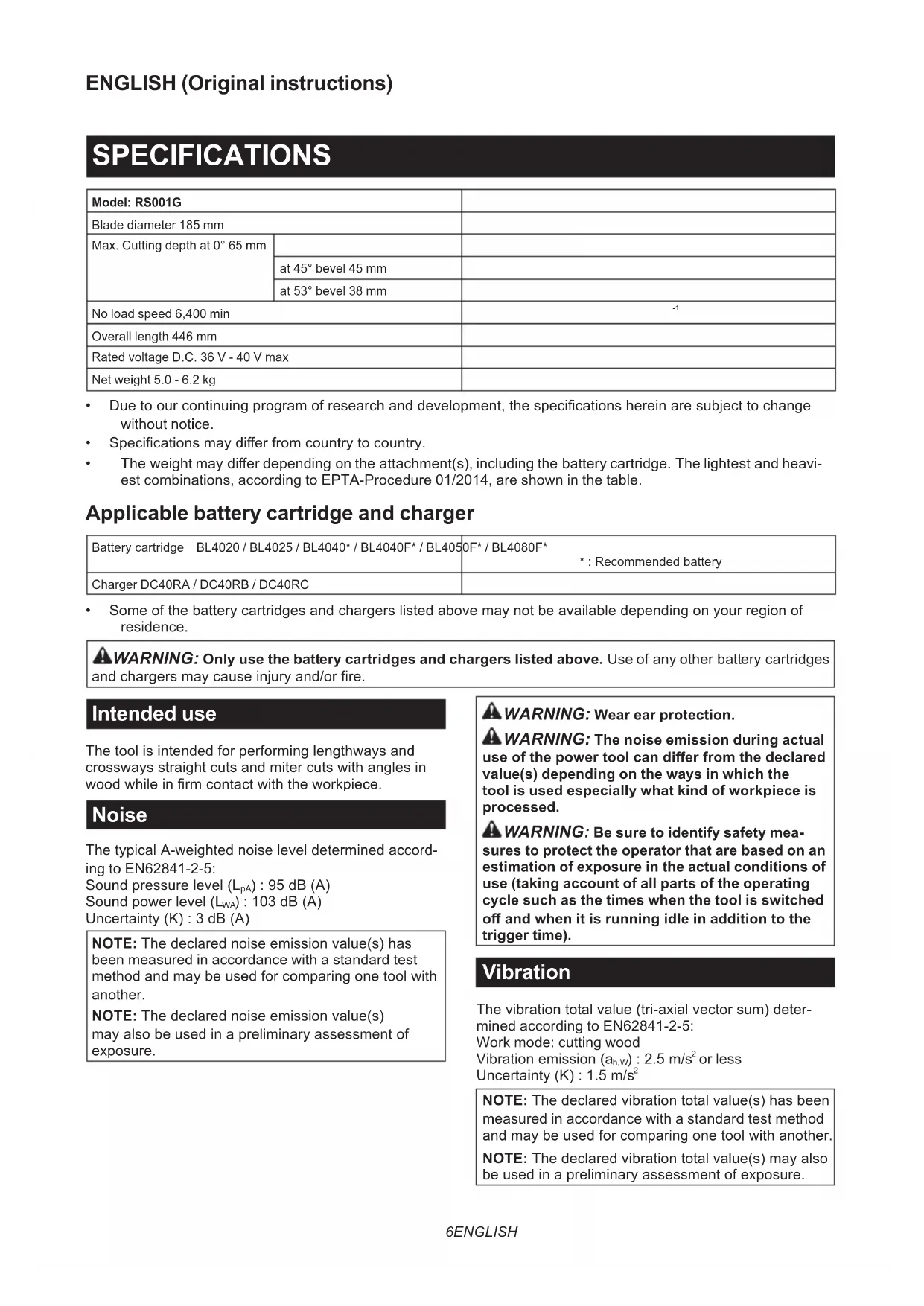
Cordless Rear Handle Saw INSTRUCTION MANUAL 6
- Specicationsmaydierfromcountrytocountry.
- Theweightmaydierdependingontheattachment(s),includingthebatterycartridge.Thelightestandheavi- est combinations, according to EPTA-Procedure 01/2014, are shown in the table. Applicable battery cartridge and charger Batterycartridge BL4020 / BL4025 / BL4040* / BL4040F* / BL4050F* / BL4080F* *:Recommendedbattery Charger DC40RA / DC40RB / DC40RC
- Someofthebatterycartridgesandchargerslistedabovemaynotbeavailabledependingonyourregionof residence.
WARNING: Only use the battery cartridges and chargers listed above.Useofanyotherbatterycartridges
WARNING: Wear ear protection.
WARNING: The noise emission during actual
use of the power tool can dier from the declared value(s) depending on the ways in which the tool is used especially what kind of workpiece is processed.
WARNING: Be sure to identify safety mea-
sures to protect the operator that are based on an estimation of exposure in the actual conditions of use (taking account of all parts of the operating cycle such as the times when the tool is switched o and when it is running idle in addition to the trigger time). Vibration Thevibrationtotalvalue(tri-axialvectorsum)deter- mined according to EN62841-2-5: Work mode: cutting wood Vibrationemission(a h,W ):2.5m/s
NOTE:Thedeclaredvibrationtotalvalue(s)hasbeen measured in accordance with a standard test method andmaybeusedforcomparingonetoolwithanother. NOTE:Thedeclaredvibrationtotalvalue(s)mayalso beusedinapreliminaryassessmentofexposure.7 ENGLISH
WARNING: The vibration emission during
actual use of the power tool can dier from the declared value(s) depending on the ways in which the tool is used especially what kind of workpiece is processed.
WARNING: Be sure to identify safety mea-
sures to protect the operator that are based on an estimation of exposure in the actual conditions of use (taking account of all parts of the operating cycle such as the times when the tool is switched o and when it is running idle in addition to the trigger time). Declarations of Conformity For European countries only TheDeclarationsofconformityareincludedinAnnexA to this instruction manual. SAFETY WARNINGS General power tool safety warnings WARNING Read all safety warnings, instruc- tions, illustrations and specications provided with this power tool. Failure to follow all instructions listed belowmayresultinelectricshock,reand/orserious injury. Save all warnings and instruc- tions for future reference. Theterm"powertool"inthewarningsreferstoyour mains-operated(corded)powertoolorbattery-operated (cordless)powertool. Cordless circular saw safety warnings Cutting procedures
DANGER: Keep hands away from cutting
area and the blade. Keep your second hand on auxiliary handle, or motor housing. If both handsareholdingthesaw,theycannotbecutby the blade.
2. Do not reach underneath the workpiece. The
guardcannotprotectyoufromthebladebelowthe workpiece.
3. Adjust the cutting depth to the thickness of
the workpiece. Less than a full tooth of the blade teeth should be visible below the workpiece.
4. Never hold the workpiece in your hands or
across your leg while cutting. Secure the workpiece to a stable platform. It is important to supporttheworkproperlytominimisebodyexpo- sure, blade binding, or loss of control. ►Fig.1
5. Hold the power tool by insulated gripping
surfaces, when performing an operation where the cutting tool may contact hidden wiring. Contact with a “live” wire will also make exposed metal parts of the power tool “live” and could give the operator an electric shock.
6. When ripping, always use a rip fence or
straight edge guide.Thisimprovestheaccuracy of cut and reduces the chance of blade binding.
7. Always use blades with correct size and shape
(diamond versus round) of arbour holes. Blades that do not match the mounting hardware ofthesawwillruno-centre,causinglossof control.
8. Never use damaged or incorrect blade wash-
ers or bolt. The blade washers and bolt were speciallydesignedforyoursaw,foroptimum performanceandsafetyofoperation. Kickback causes and related warnings — kickback is a sudden reaction to a pinched, jammedormisalignedsawblade,causingan uncontrolled saw to lift up and out of the workpiece toward the operator; — whenthebladeispinchedorjammedtightlybythe kerf closing down, the blade stalls and the motor reactiondrivestheunitrapidlybacktowardthe operator; — if the blade becomes twisted or misaligned in the cut, the teeth at the back edge of the blade can dig into the top surface of the wood causing the blade toclimboutofthekerfandjumpbacktowardthe operator. Kickbackistheresultofsawmisuseand/orincorrect operating procedures or conditions and can be avoided bytakingproperprecautionsasgivenbelow.
1. Maintain a rm grip with both hands on the
saw and position your arms to resist kickback forces. Position your body to either side of the blade, but not in line with the blade.Kickback couldcausethesawtojumpbackwards,but kickbackforcescanbecontrolledbytheoperator, if proper precautions are taken.
2. When blade is binding, or when interrupting a
cut for any reason, release the trigger and hold the saw motionless in the material until the blade comes to a complete stop. Never attempt to remove the saw from the work or pull the saw backward while the blade is in motion or kickback may occur. Investigate and take corrective actions to eliminate the cause of blade binding.
3. When restarting a saw in the workpiece, centre
the saw blade in the kerf so that the saw teeth are not engaged into the material. If a saw blade binds,itmaywalkuporkickbackfromthework- piece as the saw is restarted.
4. Support large panels to minimise the risk of
blade pinching and kickback. Large panels tend to sag under their own weight. Supports must be placed under the panel on both sides, near the line of cut and near the edge of the panel. ►Fig.2 ►Fig.3
5. Do not use dull or damaged blades.
Unsharpenedorimproperlysetbladesproduce narrow kerf causing excessive friction, blade binding and kickback.
6. Blade depth and bevel adjusting locking levers8 ENGLISH
must be tight and secure before making the cut.Ifbladeadjustmentshiftswhilecutting,itmay cause binding and kickback.
7. Use extra caution when sawing into existing
walls or other blind areas. The protruding blade maycutobjectsthatcancausekickback.
8. ALWAYS hold the tool rmly with both hands.
NEVER place your hand, leg or any part of your body under the tool base or behind the saw, especially when making cross-cuts. If kickback occurs,thesawcouldeasilyjumpbackwardsover yourhand,leadingtoseriouspersonalinjury. ►Fig.4
9. Never force the saw. Push the saw forward at a
speed so that the blade cuts without slowing. Forcing the saw can cause uneven cuts, loss of accuracy,andpossiblekickback. Lower guard function
1. Check the lower guard for proper closing
before each use. Do not operate the saw if the lower guard does not move freely and close instantly. Never clamp or tie the lower guard into the open position.Ifthesawisaccidentally dropped,thelowerguardmaybebent.Raisethe lower guard with the retracting handle and make sureitmovesfreelyanddoesnottouchtheblade oranyotherpart,inallanglesanddepthsofcut.
2. Check the operation of the lower guard spring.
If the guard and the spring are not operating properly, they must be serviced before use. Lowerguardmayoperatesluggishlydueto damagedparts,gummydeposits,orabuild-upof debris.
3. The lower guard may be retracted manually
only for special cuts such as “plunge cuts” and “compound cuts”. Raise the lower guard by the retracting handle and as soon as the blade enters the material, the lower guard must be released. For all other sawing, the lower guardshouldoperateautomatically.
4. Always observe that the lower guard is cover-
ing the blade before placing the saw down on bench or oor. An unprotected, coasting blade will cause the saw to walk backwards, cutting whatever is in its path. Be aware of the time it takes for the blade to stop after switch is released.
5. To check lower guard, open lower guard by
hand, then release and watch guard closure. Also check to see that retracting handle does not touch tool housing. Leaving blade exposed is VERY DANGEROUS and can lead to serious personalinjury. Additional safety warnings
1. Use extra caution when cutting damp wood,
pressure treated lumber, or wood containing knots. Maintain smooth advancement of tool with- out decrease in blade speed to avoid overheating the blade tips.
2. Do not attempt to remove cut material when
blade is moving. Wait until blade stops before grasping cut material.Bladescoastafterturno.
3. Avoid cutting nails. Inspect for and remove all
nails from lumber before cutting.
4. Place the wider portion of the saw base on
that part of the workpiece which is solidly supported, not on the section that will fall o when the cut is made. If the workpiece is short or small, clamp it down. DO NOT TRY TO HOLD SHORT PIECES BY HAND! ►Fig.5
5. Before setting the tool down after completing a
cut, be sure that the guard has closed and the blade has come to a complete stop.
6. Never attempt to saw with the circular saw
held upside down in a vise. This is extremely dangerous and can lead to serious accidents. ►Fig.6
7. Some material contains chemicals which may
be toxic. Take caution to prevent dust inhala- tion and skin contact. Follow material supplier safety data.
8. Do not stop the blades by lateral pressure on
9. Do not use any abrasive wheels.
10. Only use the saw blade with the diameter that
is marked on the tool or specied in the man- ual.Useofanincorrectlysizedblademayaect the proper guarding of the blade or guard opera- tionwhichcouldresultinseriouspersonalinjury.
11. Keep blade sharp and clean. Gum and wood
pitch hardened on blades slows saw and increasespotentialforkickback.Keepbladeclean byrstremovingitfromtool,thencleaningitwith gum and pitch remover, hot water or kerosene. Never use gasoline.
13. Always use the saw blade intended for cutting
the material that you are going to cut.
14. Only use the saw blades that are marked with
a speed equal or higher than the speed marked on the tool.
15. (For European countries only)
Always use the blade which conforms to EN847-1, if intended for wood and analogous materials.
16. Place the tool and the parts on a at and stable
surface.Otherwisethetoolorthepartsmayfall andcauseaninjury. SAVE THESE INSTRUCTIONS.
WARNING: DO NOT let comfort or familiarity
with product (gained from repeated use) replace strict adherence to safety rules for the subject product. MISUSE or failure to follow the safety rules stated in this instruction manual may cause serious personal injury. Important safety instructions for battery cartridge
1. Before using battery cartridge, read all instruc-
tions and cautionary markings on (1) battery charger, (2) battery, and (3) product using battery.
2. Do not disassemble or tamper with the battery
cartridge.Itmayresultinare,excessiveheat,9 ENGLISH or explosion.
3. If operating time has become excessively
shorter, stop operating immediately. It may result in a risk of overheating, possible burns and even an explosion.
4. If electrolyte gets into your eyes, rinse them
out with clear water and seek medical atten- tion right away. It may result in loss of your eyesight.
5. Do not short the battery cartridge:
(1) Do not touch the terminals with any con- ductive material. (2) Avoid storing battery cartridge in a con- tainer with other metal objects such as nails, coins, etc. (3) Do not expose battery cartridge to water or rain. A battery short can cause a large current ow, overheating, possible burns and even a breakdown.
6. Do not store and use the tool and battery car-
tridge in locations where the temperature may reach or exceed 50 °C (122 °F).
7. Do not incinerate the battery cartridge even if
it is severely damaged or is completely worn out. The battery cartridge can explode in a re.
8. Do not nail, cut, crush, throw, drop the battery
cartridge, or hit against a hard object to the battery cartridge.Suchconductmayresultina re,excessiveheat,orexplosion.
9. Do not use a damaged battery.
10. The contained lithium-ion batteries are subject
to the Dangerous Goods Legislation require- ments. Forcommercialtransportse.g.bythirdparties, forwarding agents, special requirement on pack- aging and labeling must be observed. For preparation of the item being shipped, consult- inganexpertforhazardousmaterialisrequired. Pleasealsoobservepossiblymoredetailed national regulations. Tapeormaskoopencontactsandpackupthe batteryinsuchamannerthatitcannotmove around in the packaging.
11. When disposing the battery cartridge, remove
it from the tool and dispose of it in a safe place. Follow your local regulations relating to disposal of battery.
12. Use the batteries only with the products
specied by Makita. Installing the batteries to non-compliantproductsmayresultinare,exces- siveheat,explosion,orleakofelectrolyte.
13. If the tool is not used for a long period of time,
the battery must be removed from the tool.
14. During and after use, the battery cartridge may
take on heat which can cause burns or low temperature burns. Pay attention to the han- dling of hot battery cartridges.
15. Do not touch the terminal of the tool imme-
diately after use as it may get hot enough to cause burns.
16. Do not allow chips, dust, or soil stuck into the
terminals, holes, and grooves of the battery cartridge.Itmaycauseheating,catchingre, burstandmalfunctionofthetoolorbatterycar- tridge,resultinginburnsorpersonalinjury.
17. Unless the tool supports the use near
high-voltage electrical power lines, do not use the battery cartridge near high-voltage electri- cal power lines.Itmayresultinamalfunctionor breakdownofthetoolorbatterycartridge.
18. Keep the battery away from children.
SAVE THESE INSTRUCTIONS. CAUTION: Only use genuine Makita batteries. Use of non-genuine Makita batteries, or batteries that havebeenaltered,mayresultinthebatterybursting causingres,personalinjuryanddamage.Itwill alsovoidtheMakitawarrantyfortheMakitatooland charger. Tips for maintaining maximum battery life
1. Charge the battery cartridge before completely
discharged. Always stop tool operation and charge the battery cartridge when you notice less tool power.
2. Never recharge a fully charged battery car-
tridge. Overcharging shortens the battery service life.
3. Charge the battery cartridge with room tem-
perature at 10 °C - 40 °C (50 °F - 104 °F). Let a hot battery cartridge cool down before charging it.
4. When not using the battery cartridge, remove
it from the tool or the charger.
5. Charge the battery cartridge if you do not use
it for a long period (more than six months). FUNCTIONAL DESCRIPTION CAUTION: Always be sure that the tool is switched o and the battery cartridge is removed before adjusting or checking function on the tool. Installing or removing battery cartridge CAUTION: Always switch o the tool before installing or removing of the battery cartridge. CAUTION: Hold the tool and the battery car- tridge rmly when installing or removing battery cartridge.Failuretoholdthetoolandthebattery cartridgermlymaycausethemtoslipoyourhands andresultindamagetothetoolandbatterycartridge andapersonalinjury. CAUTION: Do not use the battery adapter with the circular saw. The cable of the battery adapter may hinder the operation and result in personal injury. ►Fig.7: 1. Red indicator 2. Button 3.Batterycartridge10 ENGLISH Toremovethebatterycartridge,slideitfromthetool while sliding the button on the front of the cartridge. Toinstallthebatterycartridge,alignthetongueonthe batterycartridgewiththegrooveinthehousingandslip itintoplace.Insertitallthewayuntilitlocksinplace withalittleclick.Ifyoucanseetheredindicatoras showninthegure,itisnotlockedcompletely. CAUTION: Always install the battery cartridge fully until the red indicator cannot be seen. If not, itmayaccidentallyfalloutofthetool,causinginjuryto youorsomeonearoundyou. CAUTION: Do not install the battery cartridge forcibly.Ifthecartridgedoesnotslideineasily,itis notbeinginsertedcorrectly. Tool / battery protection system Thetoolisequippedwithatool/batteryprotectionsys- tem.Thissystemautomaticallycutsopowertothe motortoextendtoolandbatterylife.Thetoolwillauto- maticallystopduringoperationifthetoolorbatteryis placed under one of the following conditions. Overload protection Whenthetool/batteryisoperatedinamannerthat causesittodrawanabnormallyhighcurrent,thetool automaticallystops.Inthissituation,turnthetoolo and stop the application that caused the tool to become overloaded. Then turn the tool on to restart. Overheat protection Whenthetool/batteryisoverheated,thetoolstops automatically.Inthissituation,letthetoolcooldown before turning the tool on again. Overdischarge protection Whenthebatterycapacitybecomeslow,thetoolstops automatically.Iftheproductdoesnotoperateeven when the switches are operated, remove the batteries from the tool and charge the batteries. Indicating the remaining battery capacity Pressthecheckbuttononthebatterycartridgetoindi- catetheremainingbatterycapacity.Theindicatorlamps light up for a few seconds. ►Fig.8: 1. Indicator lamps 2. Check button Indicator lamps Remaining capacity Lighted O Blinking 75% to 100% 50% to 75% 25% to 50% 0% to 25% Indicator lamps Remaining capacity Lighted O Blinking Charge the battery. Thebattery mayhave malfunctioned. NOTE: Depending on the conditions of use and the ambienttemperature,theindicationmaydierslightly fromtheactualcapacity. NOTE:Therst(farleft)indicatorlampwillblinkwhen thebatteryprotectionsystemworks. Automatic speed change function This tool has "high speed mode" and "high torque mode". Thetoolautomaticallychangestheoperationmode depending on the work load. When the work load is low, the tool will run in the "high speed mode" for quicker cutting operation. When the work load is high, the tool will run in the "high torque mode" for powerful cutting operation. Adjusting depth of cut CAUTION: After adjusting the depth of cut, always tighten the lever securely. Loosen the lever on the depth guide and move the base up or down. At the desired depth of cut, secure the base bytighteningthelever. For cleaner, safer cuts, set cut depth so that no more thanonebladetoothprojectsbelowworkpiece.Using proper cut depth helps to reduce potential for danger- ousKICKBACKSwhichcancausepersonalinjury. ►Fig.9: 1. Lever Bevel cutting CAUTION: After adjusting the bevel angle, always tighten the lever securely. Loosentheleverandsetforthedesiredanglebytilting accordingly,thentightentheleversecurely. ►Fig.10: 1. Lever Positive stopper The positive stopper is useful for setting the designated anglequickly.Turnthepositivestoppersothatthe arrowonitpointsyourdesiredbevelangle(around 22.5°/45°/53°).Loosentheleverandthentiltthetool base until it stops. The position where the tool base stopsistheangleyousetwiththepositivestopper. Tighten the lever with the tool base at this position. ►Fig.11: 1. Positive stopper11 ENGLISH Sighting For straight cuts, align the 0° position on the front of the basewithyourcuttingline.For45°bevelcuts,alignthe 45° position with it. ►Fig.12: 1.Cuttingline(0°position)2. Cutting line (45°position) Switch action
WARNING: Before installing the battery car-
tridge into the tool, always check to see that the switch trigger actuates properly and returns to the "OFF" position when released.
WARNING: NEVER defeat the lock-o button
by taping down or some other means. A switch with anegatedlock-obuttonmayresultinunintentional operationandseriouspersonalinjury.
WARNING: NEVER use the tool if it runs when
you simply pull the switch trigger without press- ing the lock-o button. A switch in need of repair mayresultinunintentionaloperationandserious personalinjury.ReturntooltoaMakitaservicecenter for proper repairs BEFORE further usage. CAUTION: The tool starts to brake the cir- cular saw blade rotation immediately after you release the switch trigger. Hold the tool rmly to respond the reaction of the brake when releasing the switch trigger. Sudden reaction can drop the tool oyourhandandcancauseapersonalinjury. Topreventtheswitchtriggerfrombeingaccidentally pulled,alock-obuttonisprovided.Tostartthetool, depressthelock-obuttonandpulltheswitchtrigger. Release the switch trigger to stop. ►Fig.13: 1. Switch trigger 2.Lock-obutton NOTICE: Do not pull the switch trigger hard without pressing in the lock-o button. This can cause switch breakage. Electric brake This tool is equipped with an electric blade brake. If the toolconsistentlyfailstoquicklystopthecircularsaw blade after switch lever release, have tool serviced at a Makita service center. CAUTION: The blade brake system is not a substitute for blade guard. NEVER USE TOOL WITHOUT A FUNCTIONING BLADE GUARD. SERIOUS PERSONAL INJURY CAN RESULT. Electronic function Thetoolsequippedwithelectronicfunctionareeasyto operatebecauseofthefollowingfeature(s). Soft start feature Soft start because of suppressed starting shock. ASSEMBLY CAUTION: Always be sure that the tool is switched o and the battery cartridge is removed before carrying out any work on the tool. Oset wrench storage Whennotinuse,storetheosetwrenchasshownin theguretokeepitfrombeinglost. ►Fig.14: 1.Osetwrench Installing and removing circular saw blade CAUTION: Be sure the circular saw blade is installed with teeth pointing up at the front of the tool. CAUTION: Use only the Makita oset wrench to install or remove the circular saw blade. Installing circular saw blade NOTE:Thecircularsawblademayhavealready been installed at the time of shipment.
BOLT COUNTERCLOCKWISE SECURELY. Also be careful not to tighten the bolt forcibly. Slipping your hand from the hex wrench can cause a per- sonal injury.
WARNING: Make sure that the protrusion "a"
on the inner ange that is positioned outside ts into the saw blade hole "a" perfectly. Mounting the circular saw blade on the wrong side can result in the dangerous vibration. For tool with the inner ange for a
15.88 mm hole-diameter saw blade
BOLT COUNTERCLOCKWISE SECURELY. Also be careful not to tighten the bolt forcibly. Slipping your hand from the hex wrench can cause a per- sonal injury.
WARNING: If the ring is needed to mount the
circular saw blade onto the spindle, always be sure that the correct ring for the blade's arbor hole you intend to use is installed between the inner and the outer anges. Use of the incorrect arborholeringmayresultintheimpropermountingof the circular saw blade causing blade movement and severe vibration resulting in possible loss of control duringoperationandinseriouspersonalinjury. Removing circular saw blade
lightlytightenthehexboltbyhandtopreventloss. Blade guard cleaning When changing the circular saw blade, make sure to also clean the upper and lower blade guards of accu- mulated sawdust as discussed in the Maintenance section.Sucheortsdonotreplacetheneedtocheck lower guard operation before each use. Connecting a vacuum cleaner Optional accessory NOTE: To prevent the rubber cap from being lost, store it on the front of the tool. NOTE: When not using the vacuum cleaner, attach therubbercapontothedustnozzle. Removetherubbercapfromthedustnozzleandcon- nect the vacuum cleaner's hose. ►Fig.21: 1. Rubber cap Whenyouwishtoperformcleancuttingoperation, connectaMakitavacuumcleanertoyourtool.Connect ahoseofthevacuumcleanertothedustnozzleusing thefrontcu24. ►Fig.22: 1. Hose of the vacuum cleaner 2.Frontcu 24 3.Dustnozzle4. Rubber cap OPERATION Thistoolisintendedtocutwoodproductsonly. RefertoourwebsiteorcontactyourlocalMakitadealer for the correct circular saw blades to be used for the material to be cut. Checking blade guard function Removethebatterycartridge. Set the bevel angle to 0°, and then retract the lower guardmanuallytotheendandreleaseit.Thelower guardisproperlyfunctioningif; — itisretractedabovethebasewithoutanyhin- drance and; — itautomaticallyreturnsandcontactswiththe stopper. ►Fig.23: 1. Upper guard 2. Lower guard 3. Base
4. Stopper 5. Open 6. Close
Ifthelowerguardisnotfunctioningproperly,checkif saw dust is accumulated inside of the upper and lower guards.Ifthelowerguardisnotfunctioningproperly evenafterremovingdust,haveyourtoolservicedata Makita service center. CAUTION: Wear dust mask when performing cutting operation. CAUTION: Be sure to move the tool forward in a straight line gently. Forcing or twisting the tool will result in overheating the motor and dangerous kickback,possiblycausingsevereinjury. NOTE:Whenthebatterycartridgetemperatureis low,thetoolmaynotworktoitsfullcapacity.Atthis time,forexample,usethetoolforalight-dutycutfor awhileuntilthebatterycartridgewarmsupashigh as room temperature. Then, the tool can work to its fullcapacity. ►Fig.24 Holdthetoolrmly.Thetoolisprovidedwithbothafront grip and rear handle. Use both to best grasp the tool. Ifbothhandsareholdingsaw,theycannotbecutby the circular saw blade. Set the base on the workpiece13 ENGLISH tobecutwithoutthecircularsawblademakingany contact. Then turn the tool on and wait until the circular sawbladeattainsfullspeed.Nowsimplymovethetool forwardovertheworkpiecesurface,keepingitatand advancingsmoothlyuntilthesawingiscompleted. Togetcleancuts,keepyoursawinglinestraightand yourspeedofadvanceuniform.Ifthecutfailstoprop- erlyfollowyourintendedcutline,donotattempttoturn orforcethetoolbacktothecutline.Doingsomaybind the circular saw blade and lead to dangerous kickback andpossibleseriousinjury.Releaseswitch,waitforcir- cular saw blade to stop and then withdraw tool. Realign tool on new cut line, and start cut again. Attempt to avoid positioning which exposes operator to chips and wooddustbeingejectedfromsaw.Useeyeprotection tohelpavoidinjury. Hook CAUTION: Always remove the battery when hanging the tool with the hook. CAUTION: Never hook the tool at high loca- tions or on the surfaces where the tool may lose the balance and fall.Otherwisefallingaccidentmay occurandcauseseriousinjury. CAUTION: Do not pull the tool downward when it is hooked. CAUTION: Use the hanging/mounting parts for their intended purposes only. Using for unin- tendedpurposemaycauseaccidentorpersonal injury. Thehookisconvenientforhangingthetooltemporarily. Tousethehook,simplyliftuphookuntilitsnapsinto the open position. Whennotinuse,alwayslowerhookuntilitsnapsinto the closed position. ►Fig.25: 1. Hook 2. Open position 3. Closed position ►Fig.26 Rip fence (Guide rule) Optional accessory Thehandyripfenceallowsyoutodoextra-accurate straightcuts.Simplyslidetheripfenceupsnugly against the side of the workpiece and secure it in posi- tion with the clamping screw on the front of the base. It also makes repeated cuts of uniform width possible. ►Fig.27: 1.Ripfence(Guiderule)2. Clamping screw Lanyard (tether strap) connection Safety warnings specic for use at height Read all safety warnings and instructions. Failure tofollowthewarningsandinstructionsmayresultin seriousinjury.
1. Always keep the tool tethered when working
"at height". Maximum lanyard length is 2 m (6.5 ft). The maximum permissible fall height for lan- yard (tether strap) must not exceed 2 m (6.5 ft).
2. Use only with lanyards appropriate for this tool
type and rated for at least 7.0 kg (15.4 lbs).
3. Do not anchor the tool lanyard to anything on
your body or on movable components. Anchor the tool lanyard to a rigid structure that can withstand the forces of a dropped tool.
4. Make sure the lanyard is properly secured at
each end prior to use.
5. Inspect the tool and lanyard before each use
for damage and proper function (including fabric and stitching). Do not use if damaged or not functioning properly.
6. Do not wrap lanyards around or allow them to
come in contact with sharp or rough edges.
7. Fasten the other end of the lanyard outside
the working area so that a falling tool is held securely.
8. Attach the lanyard so that the tool will move
away from the operator if it falls. Dropped tools willswingonthelanyard,whichcouldcauseinjury or loss of balance.
9. Do not use near moving parts or running
machinery.Failuretodosomayresultinacrush orentanglementhazard.
10. Do not carry the tool by the attachment device
11. Only transfer the tool between your hands
while you are properly balanced.
12. Do not attach lanyards to the tool in a way that
keeps guards, switches or lock-os from oper- ating properly.
13. Avoid getting tangled in the lanyard.
14. Keep lanyard away from the cutting area of the
15. Use multi-action and screw gate type cara-
bineers. Do not use single action spring clip carabineers.
16. In the event the tool is dropped, it must be
tagged and removed from service, and should be inspected by a Makita Factory or Authorized Service Center. ►Fig.28: 1.Holeforlanyard(tetherstrap) MAINTENANCE CAUTION: Always be sure that the tool is switched o and the battery cartridge is removed before attempting to perform inspection or maintenance. CAUTION: Clean out the upper and lower guards to ensure there is no accumulated saw- dust which may impede the operation of the lower guarding system.Adirtyguardingsystemmaylimit the proper operation which could result in serious personalinjury.Themosteectivewaytoaccomplish this cleaning is with compressed air. If the dust is being blown out of the guards, be sure the proper eye and breathing protection is used. CAUTION: After each use, wipe o the saw dust on the tool.Finesawdustmaycomeinsidethe toolandcausemalfunctionorare.14 ENGLISH NOTICE: Never use gasoline, benzine, thinner, alcohol or the like. Discoloration, deformation or cracks may result. To maintain product SAFETY and RELIABILITY, repairs,anyothermaintenanceoradjustmentshould beperformedbyMakitaAuthorizedorFactoryService Centers,alwaysusingMakitareplacementparts. Adjusting 0°-cut accuracy Thisadjustmenthasbeenmadeatthefactory.Butifitis o,youcanadjustitasthefollowingprocedure.
3. Tighten the lever and then make a test cut to
check the verticalness. OPTIONAL ACCESSORIES CAUTION: These accessories or attachments are recommended for use with your Makita tool specied in this manual.Theuseofanyother accessories or attachments might present a risk of injurytopersons.Onlyuseaccessoryorattachment for its stated purpose. Ifyouneedanyassistanceformoredetailsregard- ingtheseaccessories,askyourlocalMakitaService Center.
WAARSCHUWING: ZORG ERVOOR DAT U
WAARSCHUWING: ZORG ERVOOR DAT U
rior 5. Perno hexagonal