
Curv 500 SE - Loudspeaker LD Systems - Free user manual and instructions
Find the device manual for free Curv 500 SE LD Systems in PDF.
| Product type | Line array subwoofer extension |
| Brand | LD Systems |
| Model | Curv 500 SE |
| Category | Loudspeaker (subwoofer) |
| Dimensions (W x H x D) | 325 x 383 x 491 mm |
| Weight | 16.5 kg |
| Power supply | 100-240 V, 50/60 Hz, 900 W max |
| Speaker | Bass reflex, 10 inches (25 cm) |
| Amplification | Class D, 300 W RMS / 1200 W peak |
| Frequency response | 47 Hz – 20 kHz |
| Connectors | 1x Satellite Out (Speakon), 1x System In (XLR 5-pin), 1x System Out (XLR 5-pin), IEC power input |
| Controls | Ground Lift selector |
| Indicators | Power LED |
| Main functions | Bass extension, Ground Lift selector, M20 threaded socket, 3 ergonomic handles |
| Cabinet material | Plywood with structured lacquer finish |
| Maintenance and cleaning | Use a dry cloth. Do not use chemicals or abrasives. Disconnect before cleaning. |
| Safety | Do not open the device. Refer all repairs to qualified personnel. Follow voltage and grounding instructions. |
| Spare parts and repairability | Contact an authorized repair center. Replaceable fuse (same type and rating). |
| Included accessories | Power cord |
| General information | Modular system compatible with Curv 500 S subwoofer and Curv 500 SAT satellites. Use only as bass extension. |
Frequently Asked Questions - Curv 500 SE LD Systems
User questions about Curv 500 SE LD Systems
0 question about this device. Answer the ones you know or ask your own.
Ask a new question about this device
Download the instructions for your Loudspeaker in PDF format for free! Find your manual Curv 500 SE - LD Systems and take your electronic device back in hand. On this page are published all the documents necessary for the use of your device. Curv 500 SE by LD Systems.
USER MANUAL Curv 500 SE LD Systems
natural_image
Modern outdoor sound equipment with a vertical stand and base unit, set against a geometric abstract background (no text or symbols visible)CURV 500®
PORTABLE ARRAY SYSTEM WITH 4-CHANNEL MIXER
LDCURV500 SERIES
CONTENTS / INHALTSVERZEICHNIS / CONTENU / CONTENIDO / TREŚĆ / CONTENUTO / 内容 / 內容
ENGLISH
PREVENTIVE MEASURES 3-4
INTRODUCTION 4
SETUP 5
CONNECTIONS, CONTROLS AND INDICATORS 6-11
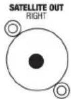
LD CURV 500® SETS, EXPANSIONS AND ACCESSORIES 12-14
SPECIFICATIONS 15
MANUFACTURER'S DECLARATIONS 16
CONFIGURATION EXAMPLES 115-116
DEUTSCH
LD CURV 500® SETS, EXPANSIONS AND ACCESSORIES 40-42
CARACTÉRISTIQUES 43-44
DECLARATIONS 44
EXEMPLES DE CONFIGURATION 115-116
ESPAÑOL
You've made the right choice!
We have designed this product to operate reliably over many years. LD Systems stands for this with its name and many years of experience as a manufacturer of high-quality audio products. Please read this User's Manual carefully, so that you can begin making optimum use of your LD Systems product quickly.
You can find more information about LD-SYSTEMS at our Internet site WWW.LD-SYSTEMS.COM
PREVENTIVE MEASURES
- Please read these instructions carefully.
- Keep all information and instructions in a safe place.
- Follow the instructions.
- Observe all safety warnings. Never remove safety warnings or other information from the equipment.
- Use the equipment only in the intended manner and for the intended purpose.
- Use only sufficiently stable and compatible stands and/or mounts (for fixed installations). Make certain that wall mounts are properly installed and secured. Make certain that the equipment is installed securely and cannot fall down.
- During installation, observ e the applicable safety regulations for your country.
- Never install and operate the equipment near radiators, heat registers, ovens or other sources of heat. Make certain that the equipment is always installed so that is cooled sufficiently and cannot overheat.
- Never place sources of ignition, e.g., burning candles, on the equipment.
- Ventilation slits must not be blocked.
- Do not use this equipment in the immediate vicinity of water (does not apply to special outdoor equipment - in this case, observe the special instructions noted below. Do not expose this equipment to flammable materials, fluids or gases. Avoid direct sunlight!
- Make certain that dripping or splashed water cannot enter the equipment. Do not place containers filled with liquids, such as vases or drinking vessels, on the equipment.
- Make certain that objects cannot fall into the device.
- Use this equipment only with the accessories recommended and intended by the manufacturer.
- Do not open or modify this equipment.
- After connecting the equipment, check all cables in order to prevent damage or accidents, e.g., due to tripping hazards.
- During transport, make certain that the equipment cannot fall down and possibly cause property damage and personal injuries.
- If your equipment is no longer functioning properly, if fluids or objects have gotten inside the equipment or if it has been damaged in another way, switch it off immediately and unplug it from the mains outlet (if it is a powered device). This equipment may only be repaired by authorized, qualified personnel.
- Clean the equipment using a dry cloth.
- Comply with all applicable disposal laws in your country. During disposal of packaging, please separate plastic and paper/cardboard.
- Plastic bags must be kept out of reach of children.
FOR EQUIPMENT THAT CONNECTS TO THE POWER MAINS
- CAUTION: If the power cord of the device is equipped with an earthing contact, then it must be connected to an outlet with a protective ground. Never deactivate the protective ground of a power cord.
- If the equipment has been exposed to strong fluctuations in temperature (for example, after transport), do not switch it on immediately. Moisture and condensation could damage the equipment. Do not switch on the equipment until it has reached room temperature.
- Before connecting the equipment to the power outlet, first verify that the mains voltage and frequency match the values specified on the equipment. If the equipment has a voltage selection switch, connect the equipment to the power outlet only if the equipment values and the mains power values match. If the included power cord or power adapter does not fit in your wall outlet, contact your electrician.
- Do not step on the power cord. Make certain that the power cable does not become kinked, especially at the mains outlet and/or power adapter and the equipment connector.
- When connecting the equipment, make certain that the power cord or power adapter is always freely accessible. Always disconnect the equipment from the power supply if the equipment is not in use or if you want to clean the equipment. Always unplug the power cord and power adapter from the power outlet at the plug or adapter and not by pulling on the cord. Never touch the power cord and power adapter with wet hands.
- Whenever possible, avoid switching the equipment on and off in quick succession because otherwise this can shorten the useful life of the equipment.
- IMPORTANT INFORMATION: Replace fuses only with fuses of the same type and rating. If a fuse blows repeatedly, please contact an authorised service centre.
- To disconnect the equipment from the power mains completely, unplug the power cord or power adapter from the power outlet.
- If your device is equipped with a Volex power connector, the mating Volex equipment connector must be unlocked before it can be removed. However, this also means that the equipment can slide and fall down if the power cable is pulled, which can lead to personal injuries and/or other damage. For this reason, always be careful when laying cables.
- Unplug the power cord and power adapter from the power outlet if there is a risk of a lightning strike or before extended periods of disuse.

CAUTION: Never remove the cover, because otherwise there may be a risk of electric shock. There are no user serviceable parts inside. Have repairs carried out only by qualified service personnel.
The lightning flash with arrowhead symbol within an equilateral triangle is intended to alert the user to the presence of uninsulated “dangerous voltage” within the product’s enclosure that may be of sufficient magnitude to constitute a risk of electrical shock.

The exclamation mark within an equilateral triangle is intended to alert the user to the presence of important operating and maintenance instructions.
CAUTION – HIGH VOLUME LEVELS WITH AUDIO PRODUCTS!
This equipment is intended for professional use. Therefore, commercial use of this equipment is subject to the respectively applicable national accident prevention rules and regulations. As a manufacturer, Adam Hall is obligated to notify you formally about the existence of potential health risks.
Hearing damage due to high volume and prolonged exposure: When in use, this product is capable of producing high sound-pressure levels (SPL) that can lead to irreversible hearing damage in performers, employees, and audience members.
For this reason, avoid prolonged exposure to volumes in excess of 90 dB.
To prevent possible hearing damage, avoid listening at high volume levels over long periods of time.
Even exposure to short bursts of loud noise can result in hearing loss. Please keep the volume constantly at a comfortable level.
* CURV500S, CURV500SE can be used in following electromagnetic environment: residential, commercial and light industrial, urban outdoors. They are the apparatus not intended for rack mounting.
* The peak inrush currents equal to 8.86 A.
*This device complies with part 15 of the FCC Rules. Operation is subject to the following two conditions: (1) this device may not cause harmful interference, and (2) this device must accept any interference received, including interference that may cause undesired operation. Changes or modifications not expressly approved by the party responsible for compliance could void the user's authority to operate the equipment.
NOTE: This equipment has been tested and found to comply with the limits for a Class B digital device, pursuant to Part 15 of the FCC Rules. These limits are designed to provide reasonable protection against harmful interference in a residential installation. This equipment generates, uses and can radiate radio frequency energy and, if not installed and used in accordance with the instructions, may cause harmful interference to radio communications. However, there is no guarantee that interference will not occur in a particular installation. If this equipment does cause harmful interference to radio or television reception, which can be determined by turning the equipment off and on, the user is encouraged to try to correct the interference by one or more of the following measures:
- Reorient or relocate the receiving antenna.
- Increase the separation between the equipment and receiver.
- Connect the equipment into an outlet on a circuit different from that to which the receiver is connected.
- Consult the dealer or an experienced radio/TV technician for help.
INTRODUCTION
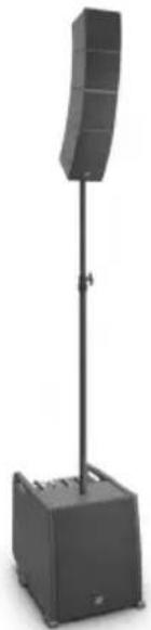
The compact, transport-friendly CURV 500 ^® is an easily configurable array system with a maximum of 4 satellites, latching into each other, which are operated via a SmartLink ^® adapter. The elements, only 12 x 12 cm in size, are equipped with LD System's own WaveAhead ^® technology, a 4" and three 1" drivers provide a coherent and extremely detailed playback with high pressure and dynamics.
The 10" bass-reflex subwoofer also houses the DSP controlled Class-D power amplifier of the CURV 500® including a limiter, protection against short circuit, overheating, over-voltage, as well as a 4-channel mixer with 16 digital effect presets and Bluetooth®. Combo, and Speakon-compatible sockets offer extensive connectivity options, and the subwoofer features 4 digital system presets, an M20 threaded flange and 3 ergonomic carrying handles. Available in 3 sets for mobile and fixed use, the convenient overall solution CURV 500® boasts a low weight and a wide, far-reaching sound dispersion.
General information
Before start-up, the subwoofer of the LD Systems CURV 500® array system must be placed upright on its rubber feet, on a flat surface. Never operate your system on a trolley, as there is a risk that the entire system might be unstable. Accidents and damage may result. To ensure adequate cooling, during operation a minimum distance of 50 cm must be maintained between the back of the subwoofer and other objects such as walls for example. Please ensure the correct connection of audio and power connections for the system and all connected devices such as mixers, CD players, etc. Use only undamaged cables of suitable diameter and always unwind cable reels completely. If necessary, use cable bridges to avoid tripping over loose cables. Never place the device directly on an edge. Do not place the subwoofer on a table. To avoid unwanted background noise when turning on connected devices, always turn on the system last and turn it off first.
SETUP
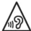
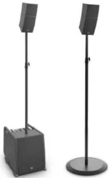
In order to allow for a wide variety of configuration options, the LD Systems CURV 500 ^® array system is designed to be modular. Described below is a representative setup of the LD CURV 500 ^® ES Entertainer Set. Examples of setups for other Sets can be found on the following pages of this user's manual.
The LD CURV 500 ^® ES Entertainer Set consists of 4 components:
A. subwoofer with mixer, built-in DSP (digital signal processor) and class-D power amplifier for the system components.
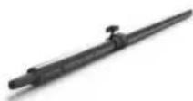
B. height adjustable spacer bar.
C. SmartLink ^® adapter as the base for up to 4 CURV 500 ^® array satellites.
D. Four CURV 500 ^® array satellites with the patented click mechanism and WaveAhead ^® technology.
Once the subwoofer (A) has been placed in the desired location, the spacer bar (B) is screwed into the subwoofer (flange on the top). When using 1 or 2 CURV 500 ^® satellites, plug the SmartLink ^® adapter (C) using the rear flange (mark satellite 1 + 2, upright position, fig. E) onto the top of the spacer bar; when using 3 or 4 CURV 500 ^® satellites using the front flange (mark satellite 3 + 4, forward inclined position, fig. F). Now slide a CURV 500 ^® satellite (D) from the rear onto the SmartLink ^® adapter (C) until it stops, while pressing the spring-loaded release button on the side of the satellite. Ensure that the two guide rails of the satellite properly slide into the grooves of the SmartLink ^® adapter in order to ensure a tight fit and establish a contact for both components. Now release the button to lock the connection and to bring the button back to its original position. Proceed in the same manner as described above to add other satellites. Now connect the speaker output SATELLITE OUT of the CURV 500 ^® subwoofer with the speaker input INPUT SIGNAL (G) of the SmartLink ^® adapter using the supplied speaker cable. When disassembling, please proceed in reverse order. For fixed installations and desktop applications, a terminal block connector (fig. H, terminal block included) is located on the back of the SmartLink ^® adapter. The speaker input INPUT SIGNAL (G) is parallel wired with the terminal block connector (H).
natural_image
Exterior view of a modern outdoor stand-mounted device with labeled components (A, B, C, D) and no visible text or symbols on the device itself.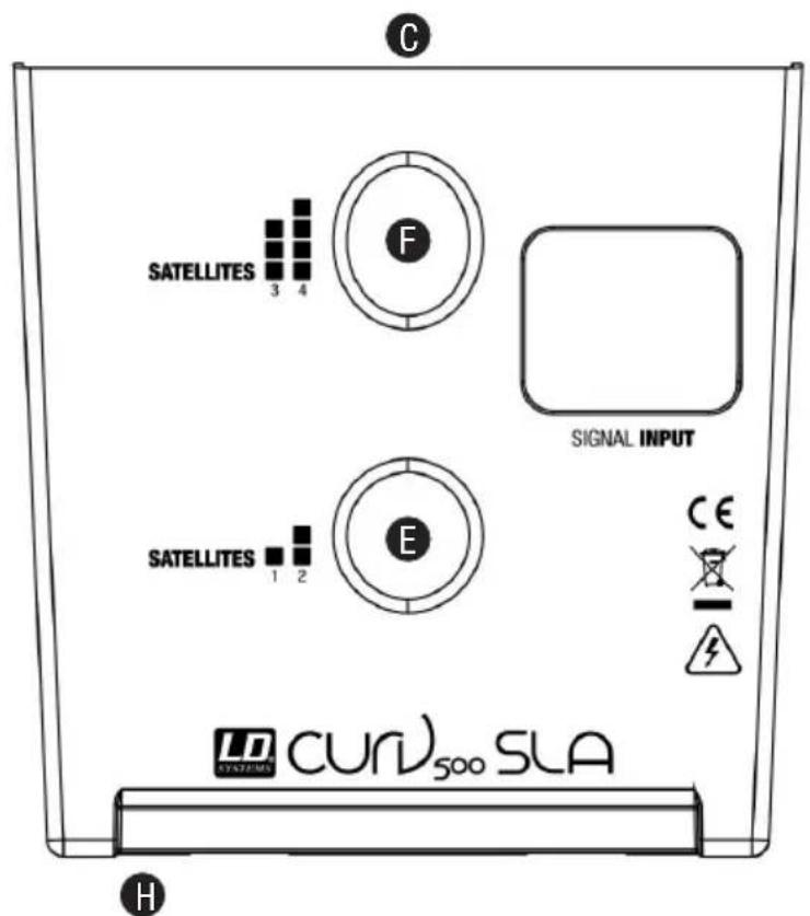
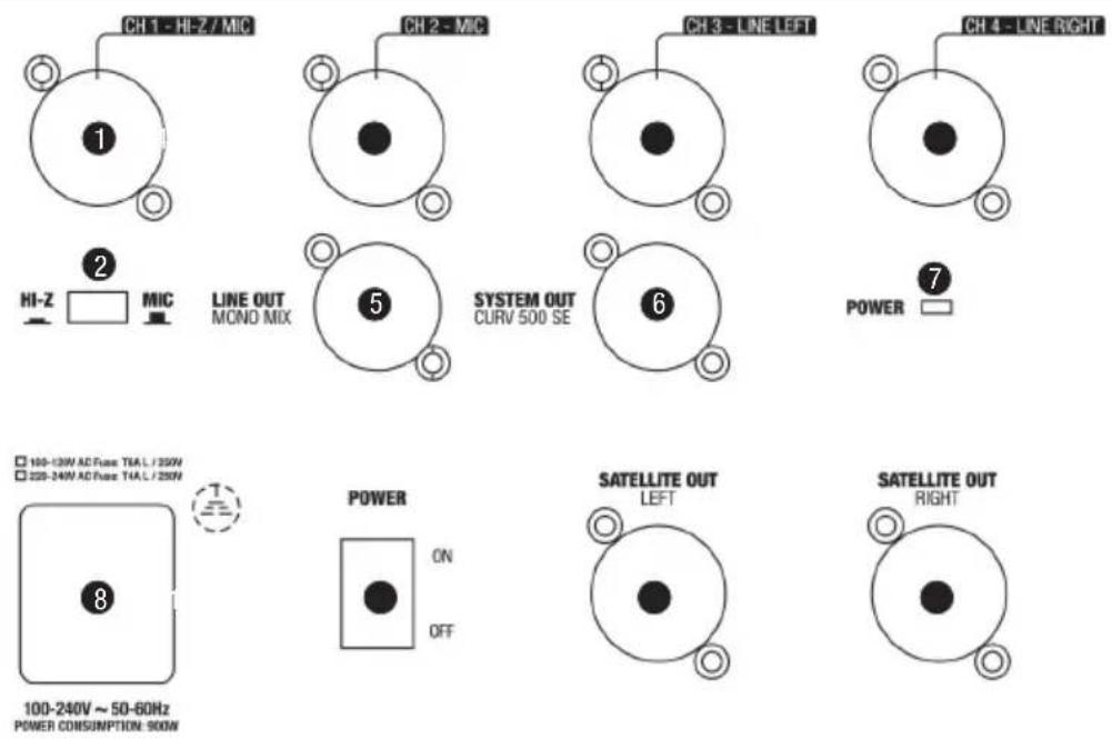
CONNECTIONS, CONTROLS AND INDICATORS
LDCURV500S
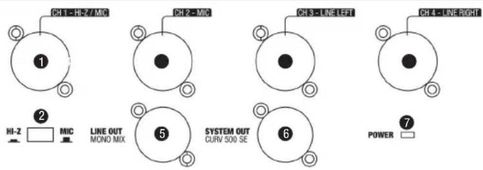
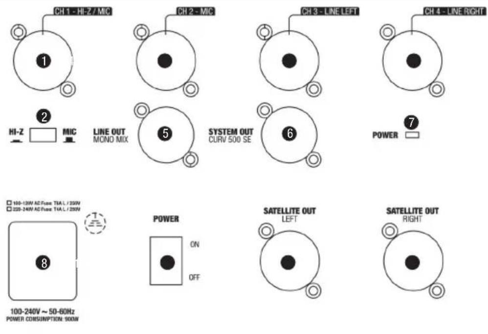
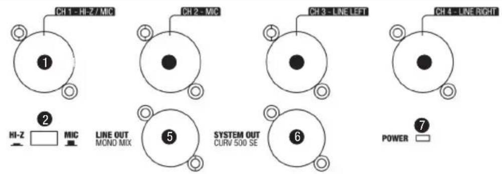
1 INPUT MIC/HI-Z
Balanced microphone or instrument input (XLR / 6.3 mm jack combo). It is also possible to use an unbalanced microphone or instrument cable (mono jack). Pay attention to the setting of switch 2, as described below. NOTE: The XLR input socket is designed for the 12 V phantom power supply of a condenser microphone.
2 HI-Z SWITCH
When using channel 1 as a microphone channel, bring the HI-Z switch to the up position. When using channel 1 as an instrument channel, bring the HI-Z switch to the down position.
3 INPUT MIC
Balanced microphone input (XLR / 6.3 mm jack combo) It is also possible to use an unbalanced microphone cable (mono jack). NOTE: The XLR input socket is designed for the 12 V phantom power supply of a condenser microphone.
4 INPUT LINE 3 + 4
Balanced line inputs with XLR / 6.3 mm jack combo sockets for connecting a playback device (e.g. mixer, keyboard). When using a CURV 500® ES Entertainer Set as a Mono Set (the array satellites mounted together on the spacer bar), the MONO / STEREO (26) switch on the mixer control panel must be pressed down (MONO). An incoming audio signal will be mono summed. When using a CURV 500® ES Entertainer Set as a Stereo Set (2 array satellites mounted left and right), or using the CURV 500® PS Power Set (Stereo), the MONO / STEREO (26) switch on the mixer control panel must not be pressed down (STEREO). An incoming stereo audio signal will be output in stereo. The latter also applies when using the LD CURV 500® AVS Stereo A/V Set (switch 26 -> STEREO).
5 LINE OUT MONO MIX
Balanced line output with male XLR socket. Output of the mixer summing signal in Mono.
6 SYSTEM OUT CURV 500 SE
Male 5-pin XLR socket to connect the CURV 500 ^® SE Subwoofer expansion, or the CURV 500 ^® PES Power expansion sets. When using a CURV 500 ^® SE Subwoofer expansion, the MONO / STEREO (26) switch on the mixer control panel must be pressed down (MONO). An incoming audio signal will be mono summed. When using a CURV 500 ^® PES Power Expansion Set to create a Stereo Set, the MONO / STEREO (26) switch on the mixer control panel must not be pressed down (STEREO). An incoming stereo signal on INPUT LINE 3 / 4 will be output in stereo.
7 POWER LED
Lights up once the system is properly connected to the power mains and switched on.
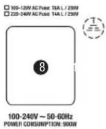
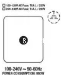
8 POWER CONNECTOR WITH FUSE HOLDER
IEC power socket with built-in fuse holder. An appropriate power cord is included in the delivery. IMPORTANT INFORMATION: Replace the fuse only with a fuse corresponding to the operating voltage. Please observe the label on the housing. If the fuse blows repeatedly, please contact an authorised service centre.
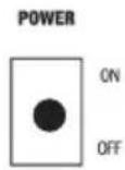
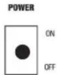
9 POWER ON / OFF
On / Off switch for the power supply of the device.
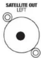
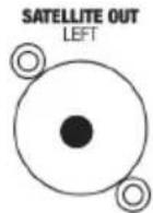
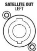
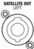
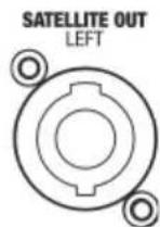
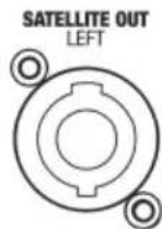
10 SATELLITE OUT LEFT / RIGHT
Speakon compatible outputs for controlling the LD CURV 500 ^® satellites. Up to four LD CURV 500 ^® satellites can be operated at each of the outputs simultaneously (e.g. for voice and sound). When using a CURV 500 ^® ES Entertainer Set as a Mono Set, use the satellite output LEFT for the control of the LD CURV 500 satellites and the MONO / STEREO (26) on the mixer control panel switch must be pressed down (MONO). When using a LD CURV 500 ^® ES Entertainer Set as a Stereo Set (2 array satellites mounted left and right), or when using the LD CURV 500 ^® AVS A/V Set, use both satellite outputs LEFT and RIGHT to control the LD CURV 500 ^® satellites left and right and the MONO / STEREO (26) switch on the mixer control panel must not be pressed down (STEREO). An incoming stereo audio signal will be output in stereo. The use of the LD CURV 500 ^® PS Power Set as a Stereo Set (or the combination of LD CURV 500 ^® ES and LD CURV 500 ^® PES) requires the use of the satellite output LEFT (left) for the control of the LD CURV 500 ^® satellite on the left. The LD CURV 500 ^® satellite on the right is controlled by the satellite output of the expansion subwoofer SATELLITE OUT RIGHT.
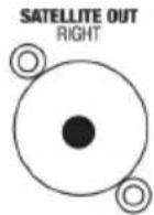
11 LED CH 1
When a signal is present at the input of channel 1 (CH 1), the LED indicator lights up green; if the LED is red, the channel is operating at the clipping range. To avoid distortion, reduce the volume level of the volume controller (12) of channel 1.
12 LEVEL CH 1
Volume controller for channel 1 (CH 1). Turning the dial to the right increases the volume and turning it to the left decreases it.
13 EQUALIZER HIGH CH 1
Equalizer high band for channel 1 (CH 1). When turned to the left, levels are lowered, when turned to the right, they are raised. In the centre position (resting point), the equalizer is inactive.
14 EQUALIZER LOW CH 1
Equalizer bass band for channel 1 (CH 1). When turned to the left, levels are lowered, when turned to the right, they are raised. In the centre position (resting point), the equalizer is inactive.
15 LEVEL DFX CH 1
Controller for adding the signal from channel 1 (Effects Send) to the internal digital effects device (effect volume channel 1). The effect presets are selected with the help of the rotary encoder DFX PRESETS N° 31.
16 LED CH 2
When a signal is present at the input of channel 2 (CH 2), the LED indicator lights up green; if the LED is red, the channel is operating in the clipping range. To avoid distortion, reduce the volume level of the volume controller (17) of channel 2.
17 LEVEL CH 2
Volume controller for channel 2 (CH 2). Turning the dial to the right increases the volume and turning it to the left decreases it.
18 EQUALIZER HIGH CH 2
Equalizer high band for channel 2 (CH 2). When turned to the left, levels are lowered, when turned to the right, they are raised. In the centre position (resting point), the equalizer is inactive.
19 EQUALIZER LOW CH 2
Equalizer bass band for channel 2 (CH 2). When turned to the left, levels are lowered, when turned to the right, they are raised. In the centre position (resting point), the equalizer is inactive.
20 LEVEL DFX CH 2
Controller for adding the signal from channel 2 (Effects Send) to the internal digital effects device (effect volume channel 2). The effect presets are selected with the help of the rotary encoder DFX PRESETS N° 31.
21 LED CH 3 / 4
When an audio signal is present at the input of channel 3 /4 (CH 3/4), the LED indicator lights up green; if the LED is red, the channel is operating in the clipping range. To avoid distortion, reduce the volume level of the playback device (e.g. keyboard, mixer) or the level of the volume controller 22.
22 LINE IN LEVEL CH 3 / 4
Volume controller for channel 3 / 4 (CH 3 / 4). Turning the dial to the right increases the volume and turning it to the left decreases it.
23 AUX INPUT
Stereo input with 3.5 mm stereo jack socket for a playback device (e.g. MP3 Player). The input is in parallel to the line inputs 3 and 4. The volume is adjusted using the volume controller of channel 3 / 4 LEVEL CH 3/4 on the playback device.
24 BLUETOOTH LED
The mixer of the LD CURV 500 ^® array system is equipped with Bluetooth, meaning that audio files from another Bluetooth device (e.g. smartphone) can be played back on the LD CURV 500 ^® speakers (maximum distance between two devices about 10 metres). If no Bluetooth device is connected with the internal Bluetooth unit, the blue Bluetooth LED flashes briefly twice every 3 seconds or so, while the pairing standby LED flashes approx. every 0.5 second; if the Bluetooth LED is on permanently, then a Bluetooth connection is established and the track playback can be started. The volume is adjusted using the volume controller of channel 3 / 4 LEVEL CH 3/4 on the playback device.
25 HOLD TO LINK
To pair and connect the internal Bluetooth device with a Bluetooth-enabled device, press and hold the HOLD to LINK button for approx. 3 seconds until the Bluetooth LED (24) flashes (approx. 2 Hz), enable Bluetooth on your Bluetooth device and search for available devices on the user interface. Select "LD CURV500®" and pair your Bluetooth device with the internal Bluetooth device. The playback can now start. To end the connection, press and hold the HOLD to LINK button again for approx. 3 seconds.
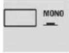
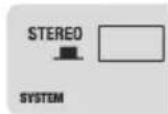
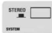
26 MONO / STEREO
To have a Mono summed output signal on the mixer, the MONO / STEREO (26) switch on the mixer control panel must be pressed down in the MONO position. If the MONO / STEREO switch is not pressed down, the output signal is in stereo.
27 MAIN LED
If an audio signal is present on the sum channel, the LED lights up green. As soon as the LD CURV 500 ^® array system is operated in the clipping range, the LED turns red. Brief flashing is not a cause for concern, since the internal audio limiter compensates for over-modulation. Permanent illumination should be avoided by reducing the input level.
28 MAIN LEVEL
Volume control for the summing channel. When turned to the left, overall volume levels are lowered, when turned to the right, they are raised.
29 SUB LEVEL
Adjusting the volume ratio of the subwoofer to the satellite speakers.
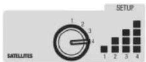
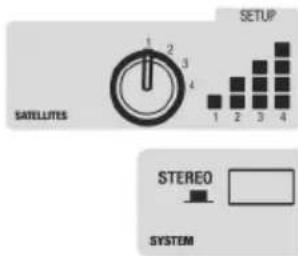
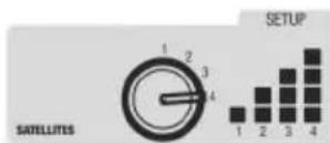
30 DSP PRESETS
Since it is possible to vary the number of connected LD CURV 500 ^® satellites (1 - 4 units), the DSP settings must be adjusted accordingly, to achieve a homogeneous sound distribution for all four variations (equalizer settings and adjusting the bass level). Set the rotary encoder on number 1 if you only want to operate one satellite in the LD CURV 500 ^® system (1 unit for mono or 1 unit each left and right for stereo). Proceed in the same way, if you want to operate 2, 3, or 4 satellites in the system.
31 DFX PRESETS
16 different effects presets are available to you. Use the rotary encoder to select one of the presets as desired.
CONNECTIONS, CONTROLS AND INDICATORS
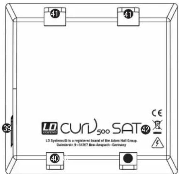
LDCURV500SE
The Subwoofer expansion LD CURV 500 ^® SE, when used individually, complements the bass output of the LD CURV 500 ^® array system. Furthermore, the subwoofer expansion allows the connection of additional LD CURV 500 ^® satellites. The intelligent signal control is carried out by the DSP (digital signal processor) integrated into the LD CURV 500 ^® S Subwoofer via the 5-pin XLR system cable, additional system settings are thus not required.
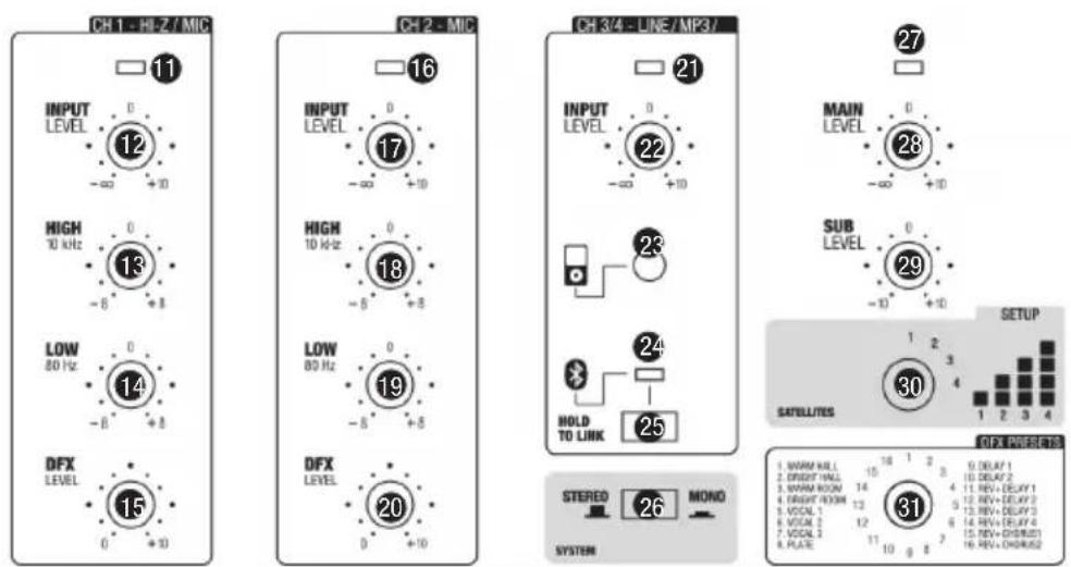
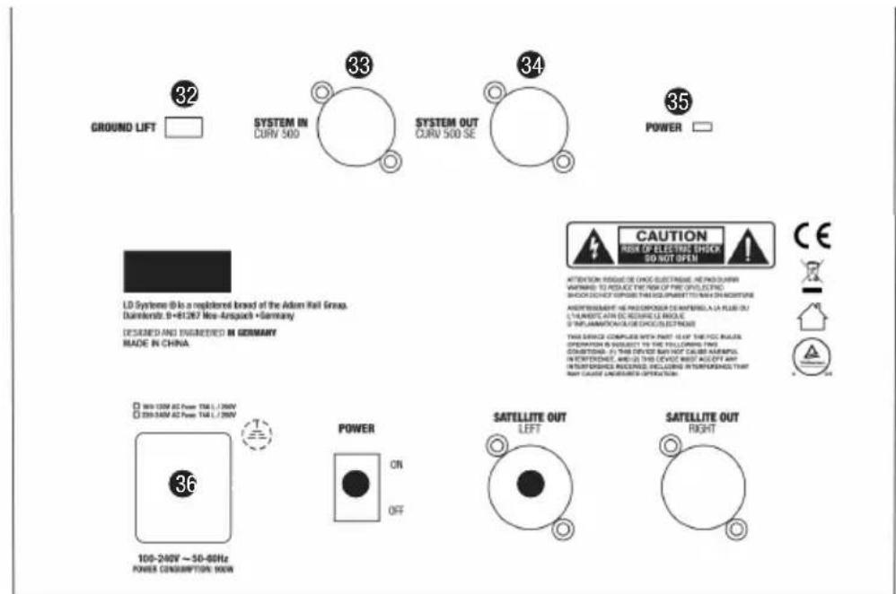
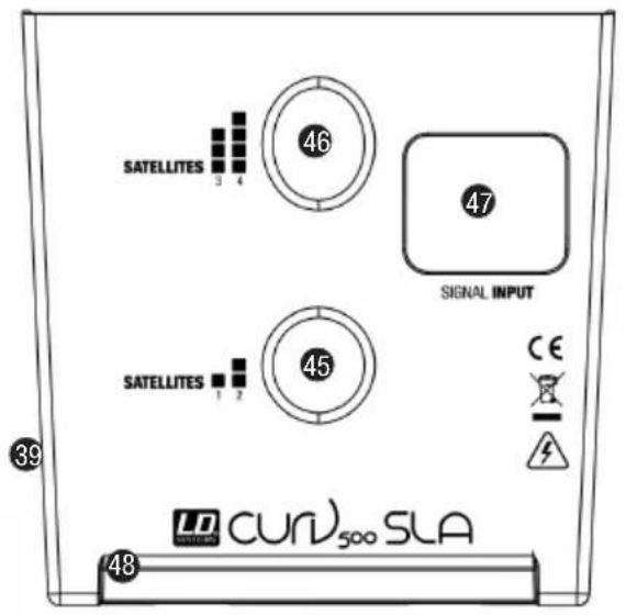
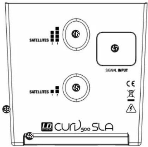
32 GROUND LIFT
This feature can prevent ground loops that can occur when the subwoofers LD CURV 500 ^® S and LD CURV 500 ^® SE are connected to different earthing potentials.
33 SYSTEM IN CURV 500
Female 5-pin XLR socket to connect the CURV 500® S Subwoofer (SYSTEM OUT N° 6 -> SYSTEM IN N° 33). A suitable 5-pin XLR system cable is included. NOTE: Use only shielded 5-pin XLR cables with parallel signal lines and full pin assignment. Some commercially available 5-pin XLR cables do not necessarily possess the full pin assignment. When using a CURV 500® SE as a subwoofer expansion, the MONO / STEREO (26) switch on the mixer control panel of the LD CURV 500® S Subwoofer must be pressed down (MONO). An incoming audio signal will be mono summed. When using a CURV 500® PES Power Expansion Set to create a Stereo Set, the MONO / STEREO (26) switch on the mixer control panel must not be pressed down (STEREO). If an incoming stereo signal is present on INPUT LINE 3 / 4 of the LD CURV 500® S Subwoofer, it will be output in stereo.
34 SYSTEM OUT CURV 500 SE
Male 5-pin XLR socket to connect an additional CURV 500® SE Subwoofer expansion, or the CURV 500® PES Power expansion sets.
35 POWER LED
Lights up once the system is properly connected to the power mains and switched on.
36 POWER CONNECTOR WITH FUSE HOLDER
IEC power socket with built-in fuse holder. A suitable power cord is included in the delivery. IMPORTANT INFORMATION: Replace the fuse only with a fuse corresponding to the operating voltage. Please observe the label on the housing. If the fuse blows repeatedly, please contact an authorised service centre.
37 POWER ON / OFF
On / Off switch for the power supply of the device.
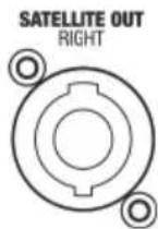
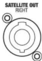
38 SATELLITE OUT RIGHT
Speakon-compatible output for controlling one to four LD CURV 500 ^® satellites. The use of the LD CURV 500 ^® PS Power Set as a Stereo Set (or the combination of LD CURV 500 ^® ES and LD CURV 500 ^® PES) requires the use of the satellite output LEFT (left) on the LD CURV 500 ^® S Subwoofer for the control of the LD CURV 500 ^® satellites on the left. The LD CURV 500 ^® satellites on the right are controlled by the satellite output of the expansion subwoofer LD CURV 500 ^® SE (SATELLITE OUT RIGHT).
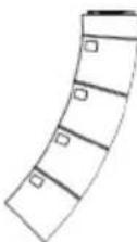
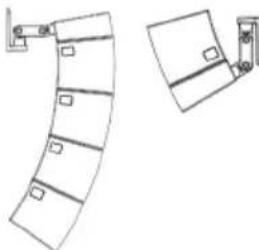
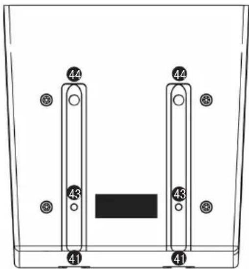
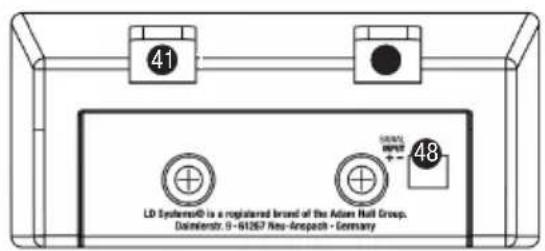
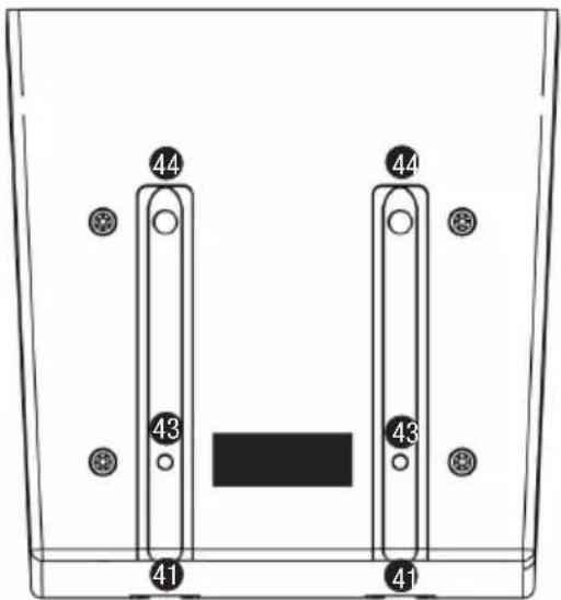
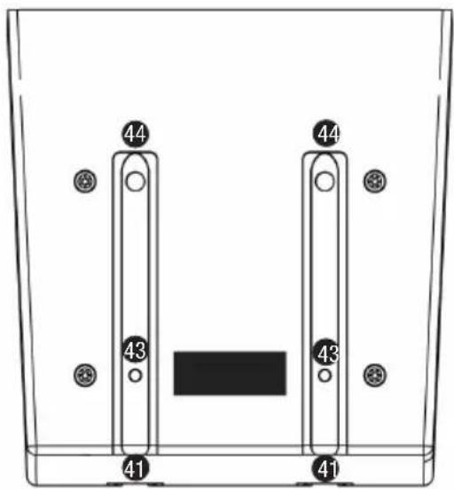
39 RELEASE BUTTON
Now slide a CURV 500 ^® satellite (LD CURV 500 ^® SAT) from the rear onto the SmartLink ^® adapter (LD CURV 500 ^® SLA) until it stops, while pressing the spring-loaded release button on the side of the satellite. Ensure that the two guide rails of the satellite (40) properly slide into the grooves (41) of the SmartLink ^® adapter or of the lower satellites, in order to ensure a tight fit and establish a contact for both components. Now release the button to lock the connection and to bring the button back to its original position. Proceed in the same manner as described above to add other satellites.
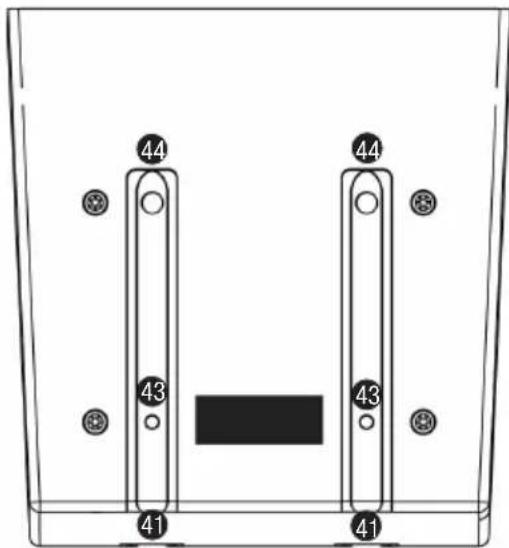

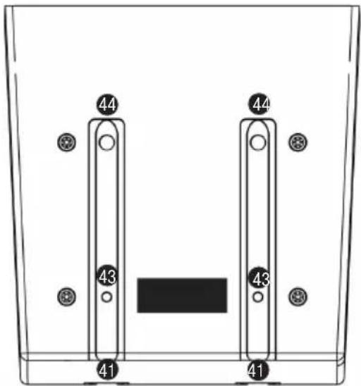
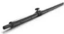
40 GUIDE RAIL LD CURV 500 SATELLITE
41 GROOVES SMARTLINK® ADAPTER OR LD CURV 500 SATELLITE
42 M3 THREAD
M3 thread to secure the LD CURV 500 ^® satellites in permanent installations.
43 LOCKING SYSTEM
44 CONTACTS
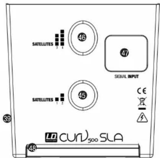
45 SATELLITE 1 / 2
Flange for 1 to 2 satellites (upright position).
46 SATELLITE 3 / 4
Flange for 3 to 4 satellites (forward tilt position).
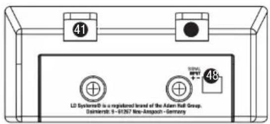
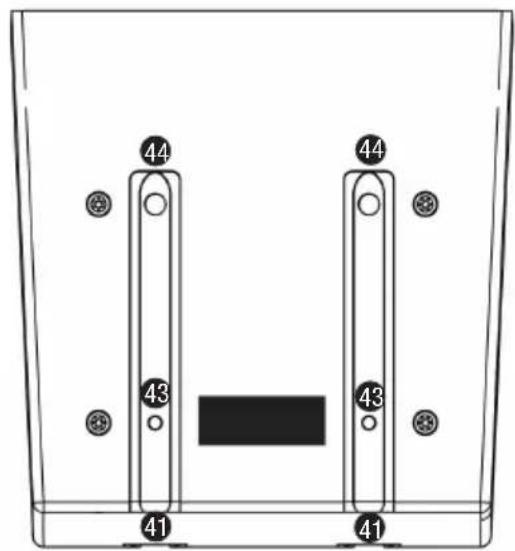
47 INPUT SIGNAL
Speakon-compatible speaker input. The speaker input INPUT SIGNAL (47) is parallel wired with the terminal block connector (48).
48 TERMINAL BLOCK CONNECTION
Terminal block connection for permanent installation and desktop application (terminal block included). The speaker input INPUT SIGNAL (47) is parallel wired with the terminal block connector (48).
LD CURV 500® SETS, EXPANSIONS AND ACCESSORIES
LD CURV 500® ES
Set Contents:
1 x LD CURV 500 ^® S Subwoofer
1 x LD CURV 500® DB Distance Bar
1 x LD CURV 500® SLA SmartLink® Adapter
4 x LD CURV 500® SAT Satellite
1 x LD CURV 500® CABLE1 Speaker cable with Speakon-compatible plugs (2.2 m)
1 x Power cable
natural_image
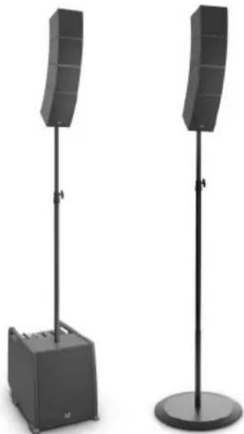
Black outdoor stand-mounted speaker with a curved top and base (no text or symbols visible)LD CURV 500® PS
Set Contents:
1 x LD CURV 500® S Subwoofer
1 x LD CURV 500® SE Subwoofer Extension
2 x LD CURV 500® DB Distance Bar
2 x LD CURV 500® SLA SmartLink® Adapter
8 x LD CURV 500® SAT Satellite
1 x LD CURV 500® CABLE3 5-pin XLR system cable (10 m)
2 x LD CURV 500® CABLE1 Speaker cable with Speakon-compatible plugs (2.2 m)
2 x Power cable
natural_image
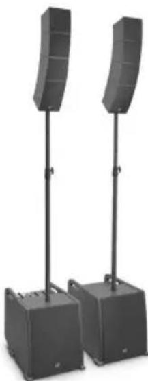
Two black outdoor audio equipment stands with curved speakers, no visible text or symbolsLD CURV 500® AVS(W)
Set Contents:
1 x LD CURV 500® S Subwoofer
2 x LD CURV 500® SLA SmartLink® Adapter
2 x LD CURV 500® SAT Satellite
2 x LD CURV 500® CABLE2 Speaker cable with Speakon-compatible plugs on terminal block (3 m)
1 x Power cable
natural_image
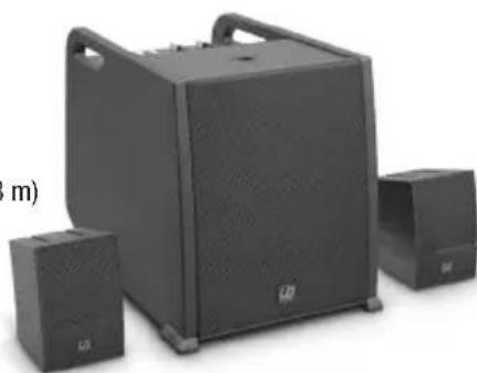
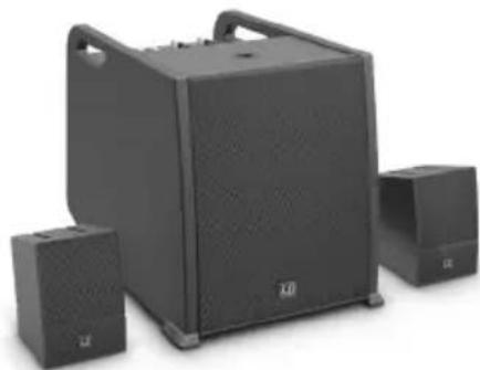
Black audio amplifier with two speakers and a large front-mounted speaker (no visible text or labels)LD CURV 500® PES(W)
Set Contents:
1 x LD CURV 500® SE Subwoofer Extension
1 x LD CURV 500® DB Distance Bar
1 x LD CURV 500® SLA SmartLink® Adapter
4 x LD CURV 500® SAT Satellite
1 x LD CURV 500® CABLE3 5-pin XLR system cable (10 m)
1 x LD CURV 500® CABLE1 Speaker cable with Speakon-compatible plugs (2.2 m)
LD CURV 500® STS
Set Contents:
1 x LD CURV 500® SSB Tripod base
1 x LD CURV 500® DB Spacer Bar
1 x LD CURV 500® SLA SmartLink® Adapter
1 x LD CURV 500® CABLE4 Speaker cable with Speakon-compatible plugs (8 m)
LD CURV 500® SE(W)
Subwoofer Extension including power cable
LD CURV 500® S2(W)
2 x LD CURV 500® SAT Satellite
LD CURV 500® SLA(W)
SmartLink ^® Adapter
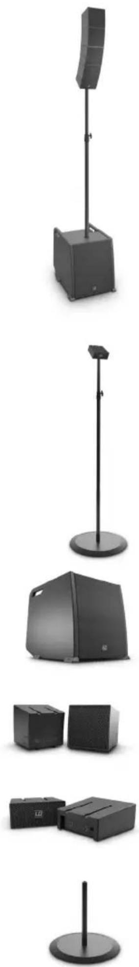
LD CURV 500® SSB
Tripod base
natural_image
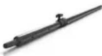
Product display of various electronic devices including a speaker tower, speaker case, and front-mounted devices (no visible text or labels)LD CURV 500 ^® DB
Distance bar
LD CURV 500® SS
Tripod base + Distance bar
LD CURV 500® CABLE1
Speaker cable with Speakon-compatible plugs (2.2 m)
LD CURV 500® CABLE2
Speaker cable with Speakon-compatible plugs on terminal block (3 m)
LD CURV 500® CABLE3
5-pin XLR system cable (10 m)
LD CURV 500® CABLE4
Speaker cable with Speakon-compatible plugs (8 m)
LD CURV 500® SATBAG
Carrying Case for 4 x satellite + 2 x SmartLink® Adapter
LD CURV 500® SUBPC
Transport trolley for CURV 500 ® Subwoofer
LD CURV 500® CMB
Ceiling mounting bracket for LD CURV 500 ^® satellites
LD CURV 500® WMB(W)
Ceiling mounting bracket for CURV 500 ^® satellites
LD CURV 500® TMB
Truss mounting adapter for CURV 500 satellites (Truss clamp not included)
natural_image
Diagram of a curved architectural or mechanical component with two views, one showing front and side details (no text or symbols)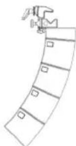
natural_image
Simple line drawing of a curved structure with a hammer and square markers (no text or symbols)Model name CURV500ES CURV500AVS CURV500PS
| Type: | Portable Array System Entertainer Set | Portable Array System AV Set | Portable Array System Power Set |
| Rated System Power (RMS): 460 W 380 W 920 W | |||
| Number of Satellites: 4 2 | 8 | ||
| Number of Adaptors: | 1 2 | 2 | |
| Number of Subwoofers: | 1 1 | 2 | |
| Max. SPL (continuous): | 122 dB | 116 dB | 128 dB |
| Max. SPL (peak): | 128 dB | 122 dB | 134 dB |
| Subwoofer 500S/SE: | 10" bass reflex | ||
| Satellite: | MF: 1 x 4" / HF: 3 x 1" with WaveAhead® Technology / 16 ohms | ||
| Frequency response: | 47 Hz - 20 kHz | ||
| Dispersion (H x V): | 110° horizontal, 10° vertical per satellite | ||
| Amplification: | Class D | ||
| Power Output (RMS/Peak): | Subwoofer: 300 W / 1200 WSatellite: 2 x 160 W / 2 x 640 W | Subwoofer: 300 W / 1200 WSatellite: 2 x 160 W / 2 x 640 WSubwoofer Extension: 300 W / 1200 W,1 x 160 W / 1 x 640 W (Satellite) | |
| Protection: | DSP based multiband-limiter, Short Circuit, Overheating, Over-current | ||
| Subwoofer 500S Features: | 4 channel mixer, Bluetooth®, 16 DFX Presets, 4 System DSP Presets, threaded M20 flange, 3 ergonomic handels | ||
| Subwoofer 500SE Features: | Ground lift, threaded M20 flange,3 ergonomic handels | ||
| Subwoofer 500S Controls: | Input Level (Ch1-4), Hi-Z, Hi/Low EQ (Ch1-2), DFX (Ch1-2), DFX Presets, DSP Presets, Blutetooth Link,Mono/Stereo, Sub Level, Main Level | ||
| Subwoofer 500SE Controls: | Ground lift | ||
| Subwoofer 500S Indicators: | Signal, Limit, Clip, Bluetooth, Power | ||
| Subwoofer 500SE Indicators: | Power | ||
| Subwoofer 500S Connectors: | 1x Mic/Hi-Z (XLR/6,3mm Jack Combo), 1x Mic (XLR/6,3mm Jack Combo), 2x Line (XLR/6,3mm JackCombo), 3,5mm Jack, 2x Satellite Out (Speakon compatible), Line Out (XLR), System Out (5-pin XLR),Mains In | ||
| Subwoofer 500SE Connectors: | 1x Satellite Out (Speakoncompatible),System In (5-pin XLR),System Out (5-pin XLR), Mains In | ||
| Subwoofer 500S/SE Material: | Plywood | ||
| Subwoofer 500S/SE Surface: | PA Painting | ||
| Satellite Features: | WaveAhead® Technology, internal crossover, metal grille, SmartLink® System | ||
| Satellite Material: | Diecast Aluminium | ||
| Satellite Surface: | Powder coating | ||
| SmartLink® Adaptor Features: | dual 16 mm flange, 4x M6 thread for optional wall/ceiling/truss mount, SmartLink® System,4x rubber feet for desktop use | ||
| SmartLink® AdaptorConnectors: | 1x Speakon compatible, 1x Terminal block | ||
| SmartLink® Adaptor Material: | Diecast Aluminium | ||
| SmartLink® Adaptor Surface: | Powder coating | ||
| Power Supply: | SMPS with PFC | ||
| Power Connector: | IEC | ||
| Operating Voltage: | AC 100-240V, 50/60Hz | ||
| Power Consumption (max.): | 900W | ||
| Temperature Range: | 0°C - 50°C | ||
| Humidity Range: | 10% - 70% rel. (non condensing) | ||
| Subwoofer Dimensions(W x H x D): | 325 x 383 x 491 mm | ||
| Satellite Dimensions(W x H x D): | 122 x 122 x 122 mm | ||
| SmartLink® AdaptorDimensions (W x H x D): | 122 x 57 x 122 mm | ||
| Subwoofer Weight: | 16,5 kg | ||
| Satellite Weight: | 1,73 kg | ||
| Adaptor Weight: | 0,54 kg | ||
MANUFACTURER'S DECLARATIONS
MANUFACTURER'S WARRANTY & LIMITATIONS OF LIABILITY
You can find our current warranty conditions and limitations of liability at: http://www.adamhall.com/media/shop/downloads/documents/manufacturersdeclarations.pdf. To request warranty service for a product, please contact Adam Hall GmbH, Daimler Straße 9, 61267 Neu Anspach / Email: Info@adamhall.com / +49 (0)6081 / 9419-0. To enquire about the current declaration of conformity, please contact info@adamhall.com.

CORRECT DISPOSAL OF THIS PRODUCT
(Valid in the European Union and other European countries with a differentiated waste collection system) This symbol on the product, or on its documents indicates that the device may not be treated as household waste. This is to avoid environmental damage or personal injury due to uncontrolled waste disposal. Please dispose of this product separately from other waste and have it recycled to promote sustainable economic activity. Household users should contact either the retailer where they purchased this product, or their local government office, for details on where and how they can recycle this item in an environmentally friendly manner. Business users should contact their supplier and check the terms and conditions of the purchase contract. This product should not be mixed with other commercial waste for disposal.
DEUTSCH
natural_image
Black outdoor stand-mounted speaker with a curved top and base (no visible text or symbols)LD CURV 500® PS
Set enthält:
natural_image
Two black outdoor audio equipment stands with curved speaker towers, no visible text or symbolsLD CURV 500® AVS(W)
Set enthält:
natural_image
Black electronic speaker setup with two speakers and a large front-mounted speaker (no visible text or labels)LD CURV 500® PES(W)
Set enthält:
natural_image
Simple line drawing of a curved architectural element with rectangular cutouts and a separate view of a door (no text or symbols)
natural_image
Simple line drawing of a curved structure with no text or symbolsTECHNISCHE DATEN
APPAREILS RELIÉS AU SECTEUR

39 BOUTON DE VERROUILLAGE
natural_image
Black outdoor audio amplifier with a vertical stand and base unit (no visible text or symbols)LD CURV 500® PS
natural_image
Two black outdoor audio equipment units with curved speaker stands, mounted on vertical poles (no text or symbols visible)LD CURV 500® AVS(W)
natural_image
Exterior view of a black audio amplifier with two speakers and a large speaker unit (no visible text or symbols)LD CURV 500® PES(W)
natural_image
Product display of various electronic devices including a speaker tower, speaker case, and front-mounted speakers (no visible text or labels)LD CURV 500 ^® DB
Barre d'espacement

LD CURV 500® SS
Base/pied + barre support
LD CURV 500® CABLE1
natural_image
Simple line drawing of a curved architectural element with rectangular cutouts and a separate view of a door handle (no text or symbols)
natural_image
Simple line drawing of a curved structure with no text or symbolsnatural_image
Exterior view of a modern outdoor stand with a curved top-mounted device and base (no text or symbols visible)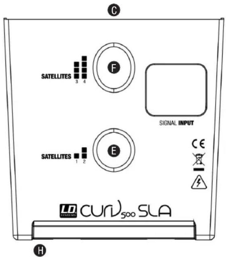
CONEXIONES, CONTROLES E INDICADORES
LDCURV500S
1 INPUT MIC/HI-Z
natural_image
Black outdoor stand-mounted speaker with curved top and base (no visible text or symbols)
natural_image
Two black outdoor audio equipment stands with curved speakers, no visible text or symbols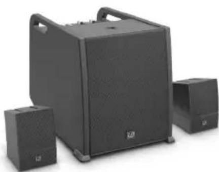
natural_image
Black audio amplifier with two speakers and a large speaker unit (no visible text or symbols)LD CURV 500® PES(W)
El modelo incluye:
natural_image
Pure architectural line drawing of a curved building facade with windows and doors, no text or symbols present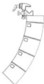
natural_image
Simple line drawing of a curved structure with no text or symbolsCARACTERÍSTICAS TÉCNICAS


39 PRZYCISK ODBLOKOWANIA
natural_image
Black outdoor audio amplifier with a vertical stand and base unit (no visible text or symbols)LD CURV 500® PS
Zawartość zestawu:
natural_image
Two black outdoor audio equipment units with curved speaker stands, mounted on support poles (no text or symbols visible)LD CURV 500® AVS(W)
Zawartość zestawu:
natural_image
Exterior view of a black audio amplifier with three speakers (no text or symbols visible)LD CURV 500® PES(W)
Zawartość zestawu:
natural_image
Product display of various electronic devices including a speaker tower, speaker case, and front-mounted speakers (no visible text or labels)LD CURV 500 ^® DB
Drażek dystansowy
LD CURV 500® SS
natural_image
Line drawing of a curved architectural or mechanical component with two views (no text or symbols)LD CURV 500® TMB
natural_image
Simple line drawing of a curved structure with no text or symbolsNazwa modelu CURV500ES CURV500AVS CURV500PS

37 POWER ON / OFF
natural_image
Black outdoor audio amplifier with a vertical stand and speaker tower (no text or symbols visible)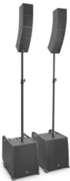
natural_image
Two black audio amplifier stands with curved speaker towers, no visible text or symbols
natural_image
Exterior view of a black audio amplifier speaker set with two speakers and a large front-mounted speaker (no visible text or symbols)LD CURV 500® PES(W)
natural_image
Product display of various outdoor sound equipment including a speaker tower, speaker chamber, and portable speakers (no visible text or labels)LD CURV 500 ^® DB
Asta distanziatrice
LD CURV 500® SS
natural_image
Simple line drawing of a curved architectural element with rectangular panels and a separate vertical panel (no text or symbols)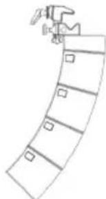
natural_image
Simple line drawing of a curved structure with no text or symbolsDenominazione del modello CURV500ES CURV500AVS CURV500PS
natural_image
Exterior view of a modern outdoor stand-mounted device with labeled components (A, B, C, D) and no visible text or symbols on the device itself.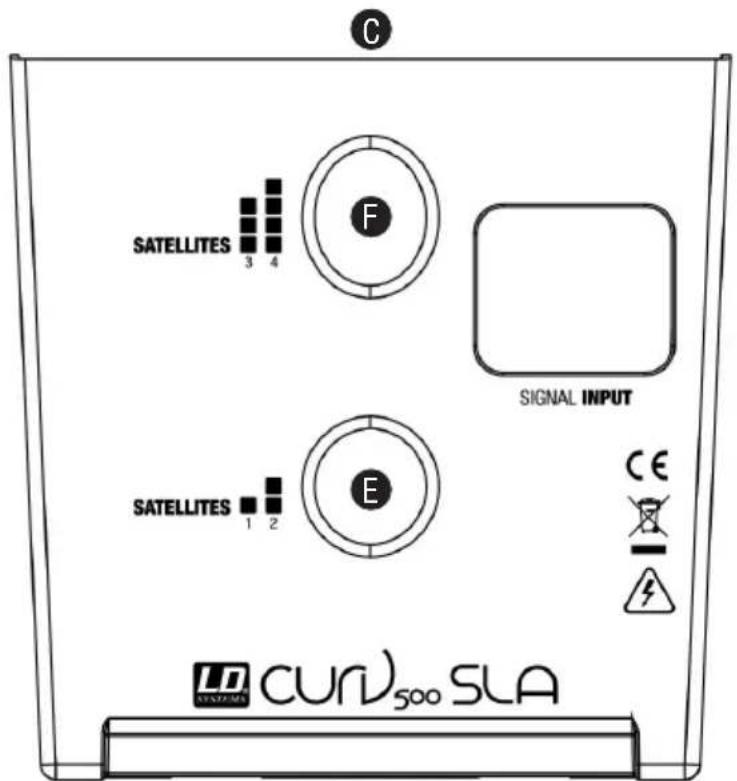
H
连接器、操作显示元件
LDCURV500S
1 INPUT MIC/HI-Z

35 POWER LED
natural_image
Black outdoor audio amplifier with a vertical stand and base unit (no visible text or symbols)
natural_image
Two black audio amplifier stands with curved speakers, mounted on two bases (no text or symbols visible)
natural_image
Exterior view of a black audio amplifier with two speakers and a large speaker unit (no visible text or symbols)LD CURV 500® PES(W)
套件包括以下部分:
natural_image
Product display of various outdoor sound equipment including a speaker tower, speaker chamber, and portable devices (no visible text or labels)LD CURV 500 ^® DB
分隔棒
LD CURV 500® SS
三脚架基座和分隔棒
LD CURV 500® CABLE1
扬声器缆线带有与 Speakon 兼容的插头 (2.2 m)
LD CURV 500® CABLE2
扬声器缆线,接线盒(3m)上与Speakon兼容的插头
LD CURV 500® CABLE3
5 极 XLR 系统缆线 (10 m)
LD CURV 500® CABLE4
natural_image
Simple line drawing of a curved architectural or mechanical component with two views (no text or symbols)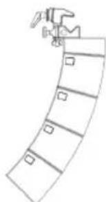
natural_image
Simple line drawing of a curved structure with a hammer and square markers (no text or symbols)技术数据
natural_image
Exterior view of a modern outdoor stand with a curved top-mounted device and base (no visible text or symbols)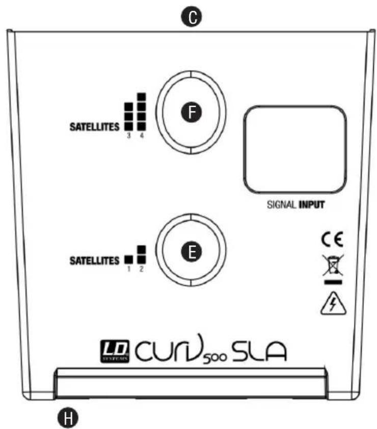
連接器、操作顯示元件
LDCURV500S
1 INPUT MIC/HI-Z
36 電源插座和保險絲座
natural_image
Exterior view of a black outdoor audio amplifier with a vertical stand (no text or symbols visible)LD CURV 500® PS
套件包括:
natural_image
Two black outdoor audio equipment units with curved speakers, standing upright (no text or symbols visible)
natural_image
Exterior view of a black audio amplifier with two speakers and a large speaker unit (no visible text or symbols)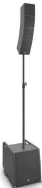
natural_image
Black outdoor stand-mounted speaker with a curved top and base, no visible text or symbolsLD CURV 500® STS
套件包括以下部分:
natural_image
Simple line drawing of a curved architectural element with rectangular panels and a separate view of a door handle (no text or symbols)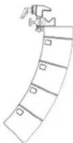
natural_image
Simple line drawing of a person climbing a curved ramp (no text or symbols)技術資料
natural_image
Black outdoor stand-mounted speaker with a curved top and base, no visible text or symbolsLD CURV 500 ^® PS (Stereo)
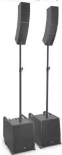
natural_image
Two black audio amplifier speakers standing upright, two emitting curved filters (no text or symbols visible)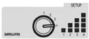

LDCURV500S LDCURV500SE
LD CURV 500 ^® ES + LD CURV 500 ^® STS (Stereo)
natural_image
Two black outdoor sound equipment stands with speakers, one centered on a box and the other standing upright (no text or symbols visible)LD CURV 500® AVS (Stereo)
natural_image
Black outdoor audio equipment with two speakers and a large speaker unit (no visible text or symbols)LD CURV 500® ES + LD CURV 500® STS + 2x LD CURV 500® S2
natural_image
Two black outdoor audio equipment stands with curved speakers and a small box base (no text or symbols visible)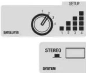


natural_image
Abstract geometric composition with overlapping translucent planes (no text or symbols)

- CURV 500®
- PORTABLE ARRAY SYSTEM WITH 4-CHANNEL MIXER
- LDCURV500 SERIES
- CONTENTS / INHALTSVERZEICHNIS / CONTENU / CONTENIDO / TREŚĆ / CONTENUTO / 内容 / 內容
- ENGLISH
- DEUTSCH
- ESPAÑOL
- You've made the right choice!
- PREVENTIVE MEASURES
- FOR EQUIPMENT THAT CONNECTS TO THE POWER MAINS
- CAUTION – HIGH VOLUME LEVELS WITH AUDIO PRODUCTS!
- INTRODUCTION
- General information
- SETUP
- CONNECTIONS, CONTROLS AND INDICATORS
- INPUT MIC/HI-Z
- HI-Z SWITCH
- INPUT MIC
- INPUT LINE 3 + 4
- LINE OUT MONO MIX
- SYSTEM OUT CURV 500 SE
- POWER LED
- POWER CONNECTOR WITH FUSE HOLDER
- POWER ON / OFF
- SATELLITE OUT LEFT / RIGHT
- LED CH 1
- LEVEL CH 1
- EQUALIZER HIGH CH 1
- EQUALIZER LOW CH 1
- LEVEL DFX CH 1
- LED CH 2
- LEVEL CH 2
- EQUALIZER HIGH CH 2
- EQUALIZER LOW CH 2
- LEVEL DFX CH 2
- LED CH 3 / 4
- LINE IN LEVEL CH 3 / 4
- AUX INPUT
- BLUETOOTH LED
- HOLD TO LINK
- MONO / STEREO
- MAIN LED
- MAIN LEVEL
- SUB LEVEL
- DSP PRESETS
- DFX PRESETS
- GROUND LIFT
- SYSTEM IN CURV 500
- SYSTEM OUT CURV 500 SE
- POWER LED
- POWER CONNECTOR WITH FUSE HOLDER
- POWER ON / OFF
- SATELLITE OUT RIGHT
- RELEASE BUTTON
- LD CURV 500® SETS, EXPANSIONS AND ACCESSORIES
- LD CURV 500® ES
- LD CURV 500® PS
- LD CURV 500® AVS(W)
- LD CURV 500® PES(W)
- LD CURV 500® STS
- LD CURV 500® SE(W)
- LD CURV 500® S2(W)
- LD CURV 500® SLA(W)
- LD CURV 500® SSB
- MANUFACTURER'S DECLARATIONS
- MANUFACTURER'S WARRANTY & LIMITATIONS OF LIABILITY
- CORRECT DISPOSAL OF THIS PRODUCT
- APPAREILS RELIÉS AU SECTEUR
- BOUTON DE VERROUILLAGE
- CONEXIONES, CONTROLES E INDICADORES
- PRZYCISK ODBLOKOWANIA
- 连接器、操作显示元件
- 連接器、操作顯示元件
- 電源插座和保險絲座
- 套件包括:
Brand : LD Systems
Model : Curv 500 SE
Category : Loudspeaker