
BST 352 V - Drill support Eibenstock - Free user manual and instructions
Find the device manual for free BST 352 V Eibenstock in PDF.
| Product type | Core drill stand |
| Brand | Eibenstock |
| Model | BST 352 V |
| Dimensions (L x W x H) | 525 x 320 x 1040 mm |
| Stand length | 995 mm |
| Weight | 22.5 kg |
| Maximum drilling diameter | 352 mm |
| Tilt | 0° to 45° |
| Final position lock | Yes |
| Motor attachment | Quick-change tool holder |
| Surface adjustment | 4 positioning screws / 2 levels |
| Order number | 09647000 |
| Available accessories | Fastening set (concrete, masonry), anchors, quick-clamping column, water collector, vacuum pump, etc. |
| Power supply | Not applicable (mechanical stand) |
| Intended use | Diamond drilling with core bits, max diameter 352 mm |
| Delivery contents | Core drill stand with handle, hex key, operating instructions |
| Maintenance | Clean the rack and sliding balls regularly; lubricate lightly |
| Safety instructions | Wear PPE (hearing protection, eye protection, helmet, gloves, safety shoes); disconnect before servicing; check fixation |
| Repairability | Repairs by qualified personnel only; spare parts available |
| Warranty | 12 months for businesses (proof required) |
| Certification | CE according to directive 2006/42/EC |
Frequently Asked Questions - BST 352 V Eibenstock
User questions about BST 352 V Eibenstock
0 question about this device. Answer the ones you know or ask your own.
Ask a new question about this device
Download the instructions for your Drill support in PDF format for free! Find your manual BST 352 V - Eibenstock and take your electronic device back in hand. On this page are published all the documents necessary for the use of your device. BST 352 V by Eibenstock.
USER MANUAL BST 352 V Eibenstock
natural_image
Green hexagonal logo with stylized letter 'E' (no text or symbols)natural_image
Mechanical device with green and black components, no visible text or symbolsDiamantbohrständer / Diamond Drill Stand / Support pour foret / Diamantboorstandaard / Supporto per trapano diamantato / Soporte para broca diamantada / Suporte para broca / Stojan pro diamantové / Stojak do wiercenia diamentowego / Stalak za dijamantnu bušilicu / Báση διαμαντιού
BST 352 V

DEUTSCH
Wichtige Hinweise
natural_image
Close-up of a mechanical component with a curved arrow indicating rotation or adjustment (no visible text or symbols)natural_image
Black electronic device with visible ports and casing (no text or symbols)
natural_image
Coiled metal pipe or hose with a small protrusion at the end (no text or symbols visible)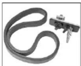
natural_image
Close-up of a black rubber band with a small metallic clip attached (no text or symbols visible)Montage Vakuumset:
natural_image
Close-up of a mechanical component with a metallic housing and attached wires (no visible text or symbols)natural_image
Close-up of a mechanical component with curved arrow indicating rotation or movement (no visible text or symbols)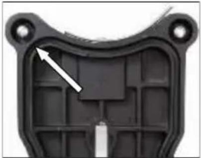
natural_image
Close-up of a black plastic mechanical component with a white arrow pointing to a specific part (no text or symbols visible)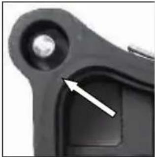
natural_image
Close-up of a mechanical component with a circular head and a highlighted section, showing no visible text or symbols.natural_image
Close-up of a mechanical component with a circular arrow indicating rotation or cycle (no text or symbols visible)natural_image
Close-up of a mechanical device with green and black components, no visible text or symbolsnatural_image
Close-up of a green and black industrial machine with mechanical components and a white arrow indicating a adjustment or operation (no visible text or symbols)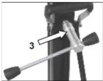
natural_image
Close-up of a mechanical device with a tool and labeled component '3' (no text or symbols beyond the number)natural_image
Close-up of a green mechanical component with two metallic bolts and three circular holes, no visible text or symbols.Important instructions and warnings are indicated by symbols:
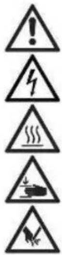
Warning of general danger
Warning of dangerous electrical voltage
Warning of hot surface
The machine, drill bit and drill stand are heavy – caution: risk of crushing
Risk of tearing or cutting
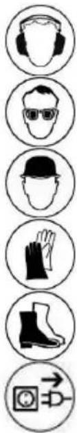
Use hearing protection
Use eye protection
Use a safety helmet
Use protective gloves
Use protective footwear
Always disconnect the power plug before working on the device!
Technical specifications
| Measures: | 525 x 320 x 1040 mm |
| Length of the column: | 995 mm |
| Weight: | 22,5 kg |
| Max. drilling diameter: | 352 mm |
| Inclination: | 0° - 45° |
| Locking in top position: | Yes |
| Fixture of the motor: | Plate fixture by mounting plate |
| Adaptation to surface: | 4 positioning screws / 2 bubble levels |
| Order number | 09647000 |
Available special accessories:
| Item | Order no. |
| Fastening set (concrete) | 35721000 |
| Fastening set (brickwork) | 35724000 |
| Spare dowel | 35722000 |
| Brickwork – dowel | 35725000 |
| Quick action bracing unit | 35730000 |
| Water suction ring WR 352 | 35873000 |
| Spare seal for water suction ring ED 352 for WR 352 | 3586L000 |
| Vacuum pump VP 04 | 09204000 |
| Vacuum tube | 35855000 |
| Vacuum set BST 352 V | 3585G000 |
Supply
Diamond drill rig with axle, turnstile, allen key and operating instruction in a cardboard box.
Application for Indented Purpose
The diamond drill rig BST 352 V is made for diamond core drills which are fixed by means of a mounting plate (e.g.: EBM 352).
The max. drilling diameter must not exceed 352 mm.
When drilling overhead, a water collecting device must be used.
In case of wrong handling or misuse, the producer does not assume any liability.
Use

After each new adjustment, check that the screws are tight so that the drill stand can be used safely.
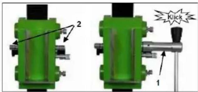
Attaching the feed lever
- Attach the turnstile (1) to the left or right of the carriage (2). This depends on the work to be carried out.
- Please check that the turnstile (1) is correctly positioned.
Fastening of the Drill Rig
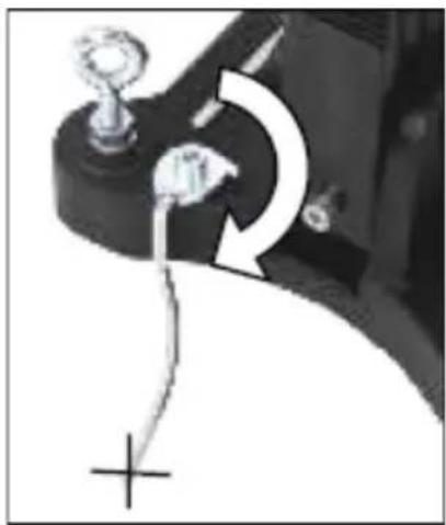
Hole centering indicator:
The drill rig is fitted with a hole centering indicator for easy and precise positioning.
natural_image
Close-up of a mechanical component with a curved arrow indicating rotation or adjustment (no visible text or symbols)Fastening with dowels in concrete
To fasten the drill stand with dowels, it is necessary to remove the vacuum grip and the foot seal from the base plate.
■ Mark the position of the mounting hole on the surface to be drilled.
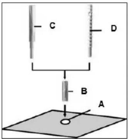
- Drill the hole (∅ 16) 50 mm deep (A) into which the M12 dowel (B) is to be inserted; insert the dowel and expand it with the dowel setting tool (C).
- Screw the quick-release screw (D) into the dowel.

Masonry anchors must be used for masonry.
- Set up the stand.
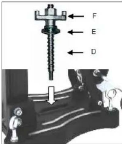
- Secure the washer (E) and finally the fastening nut (F) on the quick-release screw (D).
- Tighten the nut (F) with a 27 mm wrench.
■ Before and after tightening the nut (F), adjust the 4 adjustment screws as necessary to adapt to the surface.

Be sure to check that the stand is securely mounted.
Vacuum attachment to the floor
Do not use the vacuum attachment on walls or overhead!
For vacuum mounting, the surface to be drilled must not be porous and must be flat and free of cracks.
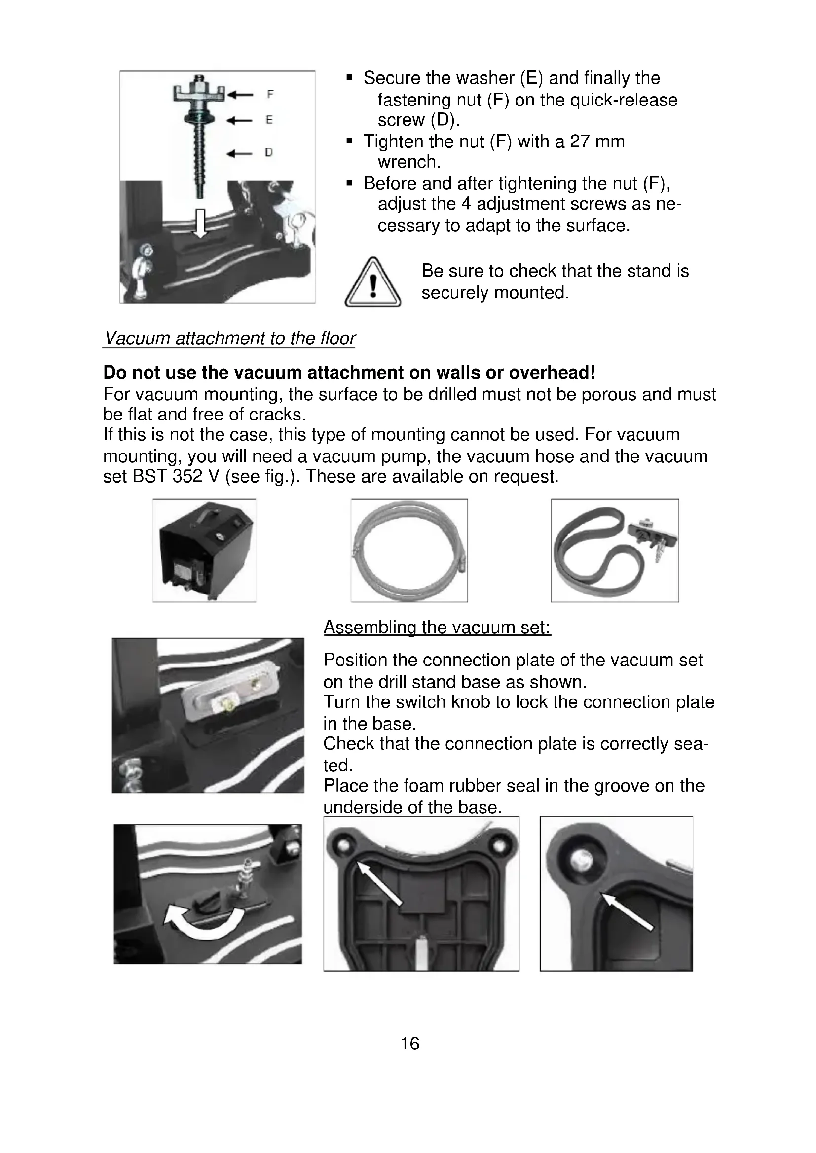
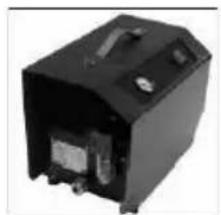
If this is not the case, this type of mounting cannot be used. For vacuum mounting, you will need a vacuum pump, the vacuum hose and the vacuum set BST 352 V (see fig.). These are available on request.
natural_image
Black electronic device with visible ports and casing (no text or symbols)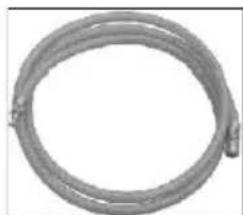
natural_image
Coiled metal pipe or hose with a small protrusion at the end (no text or symbols visible)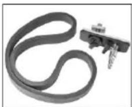
natural_image
Close-up of a black rubber band with a small metallic bracket attached (no text or symbols visible)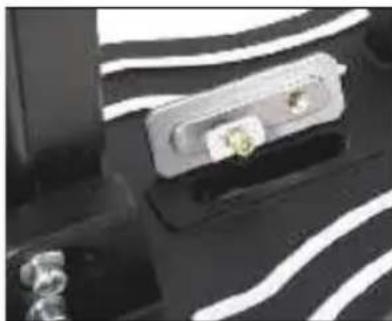
natural_image
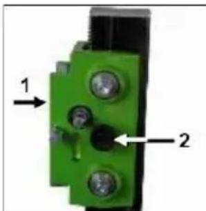
Close-up of a device with a metallic connector and a small green component, set against a black background with white wavy lines (no visible text or symbols)Assembling the vacuum set:
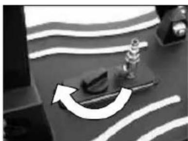
Position the connection plate of the vacuum set on the drill stand base as shown.
Turn the switch knob to lock the connection plate in the base.
Check that the connection plate is correctly seated.
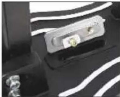
Place the foam rubber seal in the groove on the underside of the base.
natural_image
Close-up of a mechanical component with a curved arrow indicating rotation or movement (no visible text or symbols)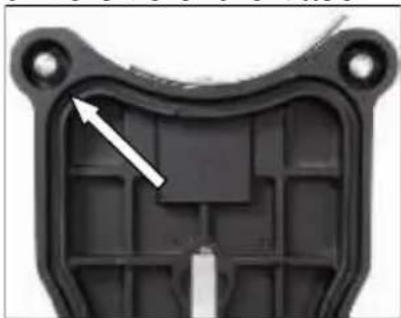
natural_image
Close-up of a black plastic mechanical component with internal grid structure and mounting holes (no text or symbols visible)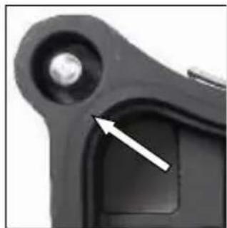
natural_image
Close-up of a mechanical component with a white arrow pointing to a specific part (no text or symbols visible)Please note that the levelling screws are adjusted so that they do not protrude from the underside of the drill stand base, as this will affect the vacuum and the stand may come loose from the surface.
When using vacuum mounting, ensure that the vacuum is sufficiently high (min. - 0.8 bar). Make sure that the seals are not worn.
Connect the drill stand and the vacuum pump using the vacuum hose.
Move the drill stand into the correct position, open the ball valve on the connection plate and switch on the pump.
The vacuum pump must continue to run throughout the entire working time and must be positioned so that you can see the pressure gauge.
Be sure to check that it is securely fastened before you start drilling!
natural_image
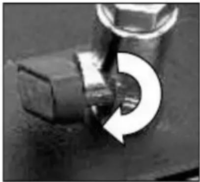
Close-up of a mechanical component with a circular arrow indicating rotation (no text or symbols)To release the vacuum attachment, close the ball valve. This opens a vent valve through which the vacuum can escape.
This allows the stand to be moved while the vacuum pump is running, if necessary.
Fastening with quick-release column
To brace the drill stand using the quick-release column, the distance to the opposite wall must be between 1.7 m and 3 m.
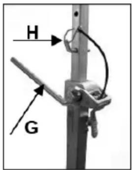
Position the drill stand. Place the quick-release column as close as possible behind the column on the stand base. Secure the drill stand by turning the crank (G) clockwise. Secure the setting with the corresponding bolt (H).
Caution!
It is important that the drill stand is firmly secured to the ground. Incorrectly secured drill stands can cause injury to the operator and damage to the drilling unit. Movement during drilling causes the drill bit to strike the borehole wall, which can lead to the segments breaking off. The drill bit can also become jammed in the borehole, causing damage to it.
Fixing the Core Drill Motor


Caution! When mounting the machine, risk of squashing. Wear protective gloves!
Assembly of the machine plate
natural_image
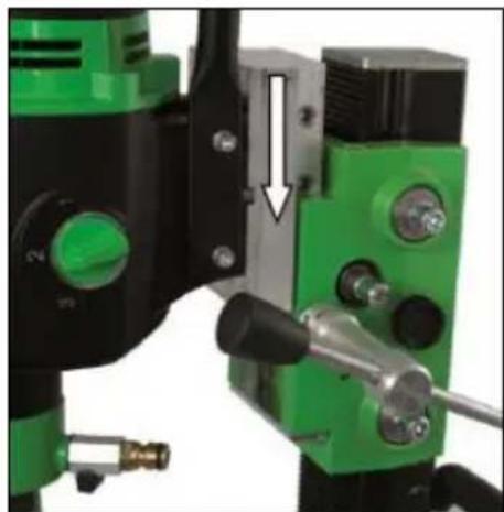
Close-up of a mechanical device with green and black components, no visible text or symbolsMove the machine holder upwards until it locks into place.
Use the feed lever to open the mounting plate lock.
Remove it and connect it to the core drilling machine as described below.
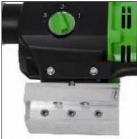
The scope of delivery includes a mounting plate, a 10 mm key and 4 M8 x 25 hexagon socket screws.
natural_image
Close-up of green and black industrial drilling equipment with a white arrow indicating a joint or adjustment (no visible text or symbols)The mounting plate is placed on the machine with the key so that the bushings in the mounting plate are on the same side as the gear shift of the machine. Then insert the four screws and tighten them securely.
Insert the core drilling machine with the mounted plate into the drill stand and lock it in place using the feed lever.

For the operation of the core drill, its operating instructions and safety advices have to be strictly observed!
Unlocking the slide:
natural_image
Close-up of a green mechanical component with two labeled parts (1 and 2), no readable text or symbols present.To unlock the carriage (1), pull out the locking button (2).
To lock the carriage, move it until the locking shaft passes through the hole in the column and locks into place.
Always lock the carriage when the assembly is not in use.
Operations
In order to operate the tool safely, please observe the following notes:
Details of the work area
- Keep the work area free of everything which could obstruct operations.
■ Provide for adequate illumination of the work area. - Adhere to the regulations concerning the power connection.
- Lay the power cable in such a way that any damage by the drill can be avoided.
- Make sure to always keep the work area in view and to be able to reach all necessary operating elements and safety installations.
- Keep other persons away from your work area in order to avoid accidents.
Space requirements for operating and maintenance
Whenever possible, keep a free space for operating and maintenance of about 2 m around the drill position, so that you can work safely and have immediate access in case of a failure.
Drilling
At the beginning, drill very slowly, since the drill bit does only starts cutting with a fraction of the cut surface in the material. If you drill too fast or with too much pressure, the drill bit could get jammed.
Angled drilling
natural_image
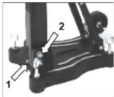
Close-up of a mechanical device with a tool and labeled component '3' (no text or symbols beyond the number)- Remove the screw (1) that locks the column at 90°.
- If necessary, loosen the two screws (2) on the side of the base plate.
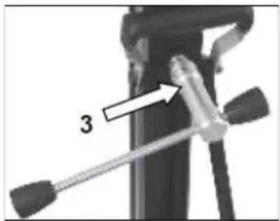
- Use the feed lever to release the lock (3) on the support.
■ Now swivel the column to the desired angle.
The scale on the tooth column makes it easier for you to set the drilling angle.
Drilling with Water
If you are cooling the drill bit with water a water collection ring is recommended.
This will be mounted with a latch fastener on the screws of the base plate and ensures a clean drilling. Mainly for overhead or lateral drilling. (see spezial-accessories).
Demounting the Core Drill Unit


- Move the machine holder with the core drill upwards until it locks in the final top position.
- Remove the drill bit.
- Loosen the locking of the mounting plate and remove the core drill machine from the drill rig
■ Loosen the fastening nut (F) - While doing so, hold the drill rig firmly!
- Remove the drill rig.
■ Unscrew the quick action clamping screw (D)
Care and Maintenance
- Always keep the drill rig clean, especially the column with the toothing and the 4 sliding balls in the machine holder. In order to allow the free movement of the pinion shaft, it should be slightly lubricated.
- In order to achieve a good performance of the drill rig, the 4 sliding balls in the machine holder have to move along the column without slackness. Attention!
After every tenth drilling you should check if the sliding pieces have got loose-fitting due to drilling vibration.
If the position should have changed, it can be readjusted as follows:
natural_image
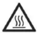
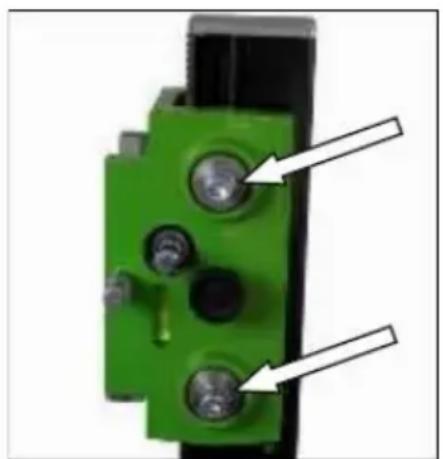
Close-up of a green mechanical component with two black pins and two white arrows pointing to features (no text or symbols visible)- Use a SW 17 open-end wrench to loosen the lock nut on the hexagon socket screw.
- Use an 8 mm hexagon key to adjust the hexagon socket screws and thus the position of the ball bearings relative to the column.
- Tighten the lock nut again and check that the machine holder moves smoothly on the guide column of the diamond drill stand.
Behavior by Malfunction
Turn off the machine by malfunction and disconnect from the electricity network. Operations on the electrical system of the machine can be executed only by a specialist.
Trouble Shooting
| Error | Possible cause | Solution |
| Drilling unit has play (vibration) | The stand has become loose. | Tighten wing nut |
| Lead has too much play | Adjust guide | |
| Sliding balls worn | Replace slide balls |
Warranty
According to the general supply conditions for business dealings, suppliers have to provide to companies a warranty period of 12 months for redhibitory defects. (to be documented by invoice or delivery note)
Damage due to natural wear, overstressing or improper handling are excluded from this warranty.
Damages due to material defects or production faults shall be eliminated free of charge by either repair or replacement.
Complaints will be accepted only if the tool is returned in non-dismantled condition to the manufacturer or an authorized Eibenstock service centre.
EU - Declaration of Conformity
It is necessary that the machine (f. e. EBM 352/3) used in this drill rig comply with the requirements which are described in the specifications of the drill rig (f. e. drilling diameter, fixture of the motor).
We declare that this unit has been designed in compliance with 2006/42/EC. This unit must not be put into service until it was established that the Power Tool to be connected to this unit is in compliance with 2006/42/EC (identified by the CE-marking on the Power Tool).
natural_image
Mechanical component with a curved arrow indicating rotation or motion (no text or symbols visible)natural_image
Black industrial electronic device with visible internal components and mounting holes (no text or symbols)
natural_image
Coiled metal pipe or hose with a small protrusion at the end (no text or symbols visible)
natural_image
Close-up of a black rubber belt with attached metal bracket (no text or symbols visible)natural_image
Close-up of electronic components with metallic contacts and traces (no visible text or symbols)natural_image
Close-up of a mechanical component with curved arrow indicating rotation or movement (no visible text or symbols)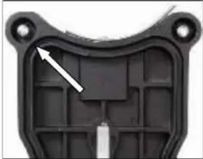
natural_image
Close-up of a black plastic mechanical component with internal grid structure and mounting holes (no text or symbols visible)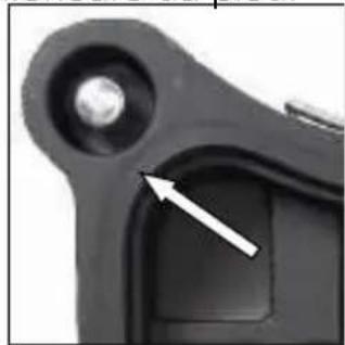
natural_image
Close-up of a mechanical component with a white arrow pointing to a specific part (no visible text or symbols)natural_image
Close-up of a mechanical component with a circular arrow indicating rotation or change (no text or symbols visible)natural_image
Close-up of a mechanical device with green and black components, no visible text or symbolsnatural_image
Close-up of a green and black industrial machine with a white arrow pointing to a component (no visible text or symbols)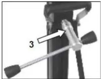
natural_image
Close-up of a green mechanical component with two metallic pins and a black base, no visible text or symbols.natural_image
Close-up of a mechanical component with a curved arrow indicating rotation or adjustment (no visible text or symbols)natural_image
Black electronic device casing with visible internal components and mounting holes (no text or symbols)
natural_image
Coiled metal pipe or hose with two connectors, no visible text or symbols
natural_image
Close-up of a black rubber band with a small metallic clip attached (no text or symbols visible)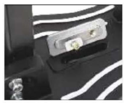
natural_image
Close-up of a black electronic device with white wavy lines and two metallic connectors (no visible text or symbols)De vacuümset monteren:
natural_image
Close-up of a mechanical component with a curved arrow indicating rotation or movement (no visible text or symbols)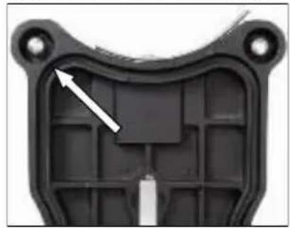
natural_image
Close-up of a black plastic mechanical component with a white arrow pointing to a specific area (no text or symbols visible)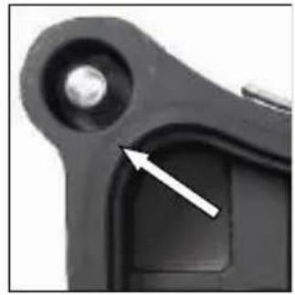
natural_image
Close-up of a mechanical component with a white arrow pointing to a small circular feature (no text or symbols visible)natural_image
Close-up of a mechanical component with a curved arrow indicating rotation (no text or symbols visible)natural_image
Close-up of a mechanical device with green and black components, no visible text or symbolsnatural_image
Close-up of a green and black industrial machine tool with a white arrow indicating a adjustment or operation (no visible text or symbols)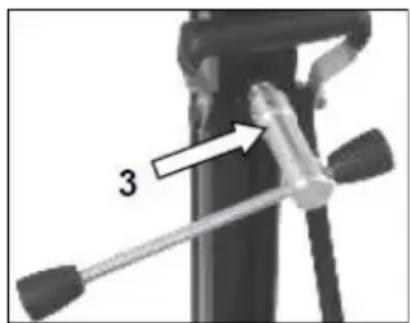
natural_image
Close-up of a mechanical device with a tool and labeled component '3' (no text or symbols beyond the number)natural_image
Close-up of a green mechanical component with three circular holes and two white arrows pointing to features (no text or symbols visible)natural_image
Mechanical component with a curved arrow indicating rotation or motion (no text or symbols visible)natural_image
Black electronic device with visible ports and components (no text or symbols)
natural_image
Coiled metal pipe or hose with a small protrusion at the end (no text or symbols visible)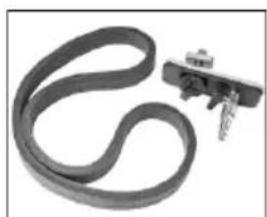
natural_image
Close-up of a black rubber band with a small metallic clip attached (no text or symbols visible)natural_image
Close-up of a mechanical component with white wavy lines and a small green component (no visible text or symbols)natural_image
Close-up of a mechanical component with a curved arrow indicating rotation or movement (no visible text or symbols)
natural_image
Close-up of a black plastic mechanical component with internal grid structure and mounting holes (no text or symbols visible)
natural_image
Close-up of a mechanical component with a white arrow pointing to a small feature (no text or symbols visible)natural_image
Close-up of a mechanical component with a circular arrow indicating rotation (no text or symbols visible)natural_image
Close-up of a mechanical component with green and black parts, no visible text or symbolsnatural_image
Close-up of a green and black industrial machine tool with a white arrow indicating a adjustment or operation (no visible text or symbols)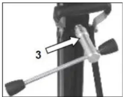
natural_image
Close-up of a green mechanical component with two metallic pins and a black housing (no visible text or symbols)natural_image
Mechanical component with a curved arrow indicating rotation or motion (no text or symbols visible)natural_image
Black electronic device with visible ports and casing (no text or symbols)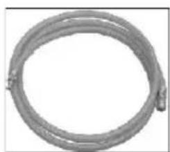
natural_image
Coiled metal pipe or hose with a small protrusion at the end (no text or symbols visible)
natural_image
Close-up of a black rubber band with a metallic clip attached (no text or symbols visible)natural_image
Close-up of a mechanical component with white wavy lines and a small green component (no visible text or symbols)natural_image
Close-up of a mechanical component with a curved arrow indicating rotation or movement (no visible text or symbols)
natural_image
Close-up of a black plastic mechanical component with internal cavities and mounting holes (no text or symbols visible)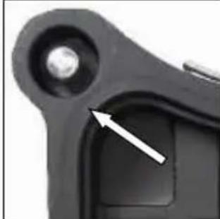
natural_image
Close-up of a mechanical component with a white arrow pointing to a specific part (no visible text or symbols)natural_image
Close-up of a mechanical component with a circular arrow indicating rotation or cycle (no text or symbols visible)natural_image
Close-up of a mechanical device with green and black components, no visible text or symbolsnatural_image
Close-up of a green industrial machine with black and white components, showing a mechanical assembly with a white arrow indicating a component (no visible text or symbols)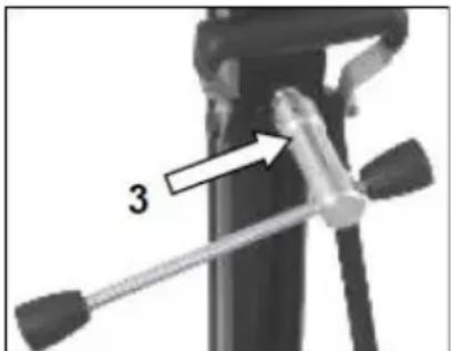
natural_image
Close-up of a mechanical device with a labeled component '3' and a tool handle (no readable text or symbols beyond the number)natural_image
Close-up of a green mechanical component with two white arrows pointing to specific features (no text or symbols visible)natural_image
Mechanical component with a curved arrow indicating rotation or motion (no text or symbols visible)natural_image
Black electronic device with visible ports and casing (no text or symbols)
natural_image
Coiled metal pipe or hose with a looped end, no visible text or symbols
natural_image
Close-up of a black rubber band with a metallic clip attached (no text or symbols visible)natural_image
Close-up of a mechanical component with white wavy lines and a small yellow connector (no visible text or symbols)natural_image
Close-up of a mechanical component with a curved arrow indicating rotation or movement (no visible text or symbols)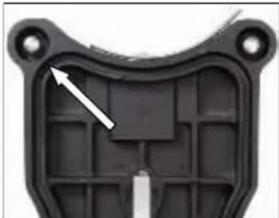
natural_image
Close-up of a black plastic mechanical component with internal grid structure and mounting holes (no text or symbols visible)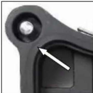
natural_image
Close-up of a black mechanical component with a circular hole and a white arrow pointing to a specific area (no text or symbols visible)natural_image
Close-up of a mechanical component with a circular arrow indicating rotation (no text or symbols visible)natural_image
Close-up of a mechanical device with green and black components, no visible text or symbolsnatural_image
Close-up of a green and black industrial machine tool with a white arrow indicating a adjustment or operation (no visible text or symbols)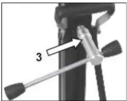
natural_image
Close-up of a mechanical device with a tool and a numbered arrow pointing to a component (no text or symbols visible)natural_image
Close-up of a green mechanical component with two metallic pins and a black housing (no text or symbols visible)natural_image
Mechanical component with a curved arrow indicating rotation or motion (no visible text or symbols)natural_image
Black electronic device with visible ports and casing (no text or symbols)
natural_image
Coiled metal pipe or hose with no visible text or symbols
natural_image
Close-up of a black rubber band with a metal clip attached (no text or symbols visible)natural_image
Close-up of a mechanical component with a metallic housing and attached cable, set against a patterned background (no visible text or symbols)natural_image
Close-up of a mechanical component with a curved arrow indicating rotation or movement (no visible text or symbols)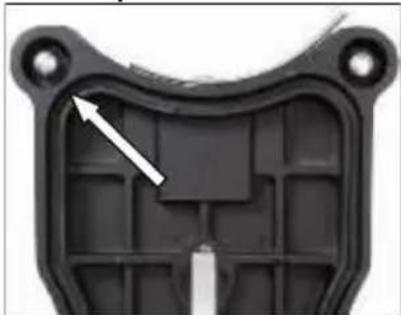
natural_image
Close-up of a black plastic mechanical component with internal grid structure and mounting holes (no text or symbols visible)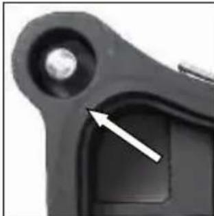
natural_image
Close-up of a mechanical component with a circular hole and a white arrow pointing to a small square feature (no text or symbols visible)natural_image
Close-up of a mechanical component with a circular arrow indicating rotation (no text or symbols visible)natural_image
Close-up of a mechanical component with green and black parts, no visible text or symbolsnatural_image
Close-up of mechanical components with green and black parts, no visible text or symbols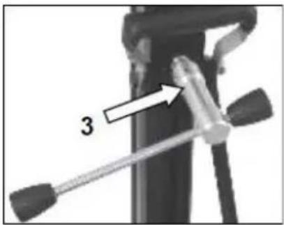
natural_image
Close-up of a mechanical device with a lever and handle, labeled with number 3 (no text or symbols on the device itself)natural_image
Close-up of a green mechanical component with three circular holes and two white arrows pointing to features (no text or symbols visible)natural_image
Mechanical component with a curved arrow indicating rotation or motion (no visible text or symbols)natural_image
Black electronic device with visible ports and casing (no text or symbols)
natural_image
Coiled metal pipe or hose with a small protrusion at the end (no text or symbols visible)
natural_image
Close-up of a black rubber band with a small mechanical clamp attached (no text or symbols visible)natural_image
Close-up of a device with a white plastic housing and a small green label, set against a black background with faint white wavy lines (no readable text or symbols)natural_image
Close-up of a mechanical component with a curved arrow indicating rotation or motion (no visible text or symbols)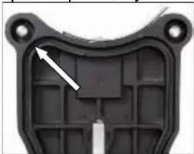
natural_image
Close-up of a black plastic mechanical component with internal grid structure and mounting holes (no text or symbols visible)
natural_image
Close-up of a black mechanical component with a circular hole and a white arrow pointing to a specific part (no text or symbols visible)natural_image
Close-up of a mechanical component with a circular arrow indicating rotation (no text or symbols visible)natural_image
Close-up of a mechanical device with green and black components, no visible text or symbolsnatural_image
Close-up of a green and black industrial machine with mechanical components and a white arrow indicating a adjustment or operation (no visible text or symbols)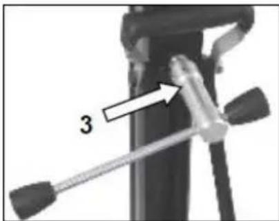
natural_image
Close-up of a green mechanical component with two circular holes and three central holes, mounted on a black base (no text or symbols visible)natural_image
Mechanical component with a curved arrow indicating rotation or motion (no visible text or symbols)- Označite središte rupe koju treba izbušiti.
natural_image
Black electronic device with visible ports and components (no text or symbols)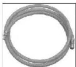
natural_image
Coiled metal pipe or hose with no visible text or symbols
natural_image
Close-up of a black rubber band with a small metallic clip attached (no text or symbols visible)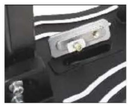
natural_image
Close-up of a black electronic device with white wavy lines and two small connectors (no visible text or symbols)Ugradnja vakuumskog seta
Postavite spojnu ploču vakuumskog seta na osnovu postolja za bušenje kao što je prikazano.
natural_image
Close-up of a mechanical component with a curved arrow indicating rotation or movement (no visible text or symbols)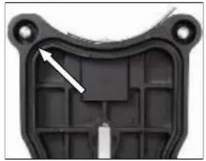
natural_image
Close-up of a black plastic mechanical component with a white arrow pointing to a specific area (no text or symbols visible)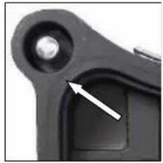
natural_image
Close-up of a mechanical component with a white arrow pointing to a small circular feature (no text or symbols visible)Provjerite je li vijak za nivelaciju pravilno podešen tako da ne viri iz dna postolja, jer bi to moglo smanjiti učinak vakuuma i uzrokovati otpuštanje postolja s površine.
Prilikom spajanja vakuuma (min. – 0,8 bara) obavezno provjerite jesu li brtve u dobrom stanju.
natural_image
Close-up of a mechanical component with a circular arrow indicating rotational motion (no text or symbols visible)natural_image
Close-up of a black electrical connector with green and gray components, no visible text or symbols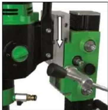
natural_image
Close-up of a mechanical assembly with green and black components, no visible text or symbols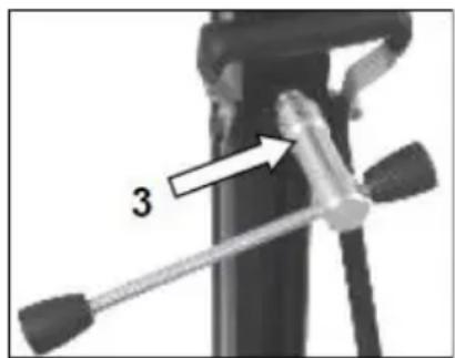
■ Uklonite vijak (1) koji zaključava stup pod kutom od 90°.
- Po potrebi otpustite dva bočna vijka (2) na osnovnoj ploči.
- Otpustite steznu spojnicu (3) na nosaču pomoću ručice za pomicanje.
- Zakrenite stup dok ne postignete željeni kut.
- Ponovno zategnite dva vijka (2) i steznu spojnicu (3).
Skala na nazubljenom stupu olakšava podešavanje kuta bušenja.
Bušenje s vodom
Ako svrdlo hladite vodom, preporučuje se korištenje prstena za skupljanje vode.
On se pričvršćuje pomoću kopče na vijke osnovne ploče i osigurava čisto bušenje.
natural_image
Close-up of a green mechanical component with two circular holes and three threaded holes, mounted on a black base (no text or symbols visible)- Otpustite kontra-maticu na imbus vijku pomoću ključa 17.
- Podesite imbus vijke i položaj kuglica u odnosu na stup pomoću imbus ključa 8.
- Ponovno zategnite kontra-maticu i provjerite kreće li se kolica glatko po stupu.
natural_image
Mechanical component with a curved arrow indicating rotation or motion (no visible text or symbols)natural_image
Black industrial electrical enclosure with visible components and mounting holes (no text or symbols)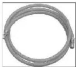
natural_image
Coiled metal pipe or hose with no visible text or symbols
natural_image
Close-up of a black rubber band with a small attached clip (no text or symbols visible)natural_image
Close-up of a mechanical component with white wavy lines and a small green component (no visible text or symbols)natural_image
Close-up of a mechanical component with a curved arrow indicating rotation or movement (no visible text or symbols)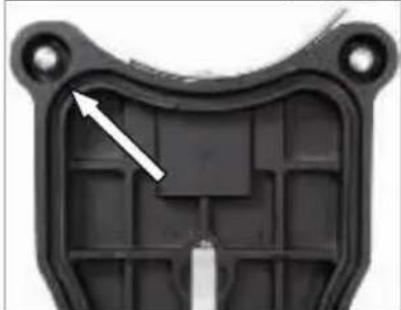
natural_image
Close-up of a black plastic mechanical component with internal cavities and mounting holes (no text or symbols visible)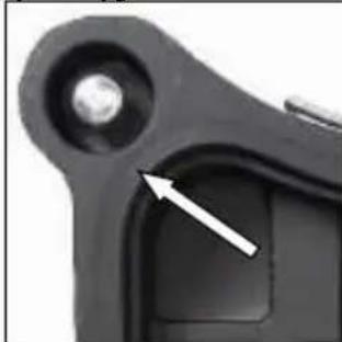
natural_image
Close-up of a mechanical component with a white arrow pointing to a small feature (no text or symbols visible)natural_image
Close-up of a mechanical component with a circular arrow indicating rotation or cycle (no text or symbols visible)natural_image
Close-up of a black electrical connector with green and gray components, no visible text or symbolsnatural_image
Close-up of green and black industrial drilling equipment with a white arrow indicating a mechanical component (no visible text or symbols)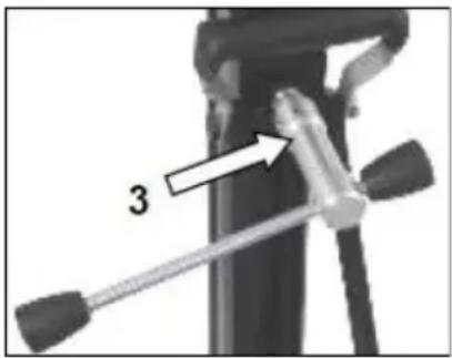
natural_image
Close-up of a mechanical device with a tool and labeled component '3' (no text or symbols beyond the number)natural_image
Close-up of a green mechanical component with two white arrows pointing to specific features (no text or symbols visible)Your specialist dealer
- BST 352 V
- DEUTSCH
- Wichtige Hinweise
- Montage Vakuumset:
- Technical specifications
- Supply
- Application for Indented Purpose
- Use
- Attaching the feed lever
- Fastening of the Drill Rig
- Fastening with dowels in concrete
- Do not use the vacuum attachment on walls or overhead!
- The vacuum pump must continue to run throughout the entire working time and must be positioned so that you can see the pressure gauge.
- Be sure to check that it is securely fastened before you start drilling!
- Fastening with quick-release column
- Caution!
- Fixing the Core Drill Motor
- Caution! When mounting the machine, risk of squashing. Wear protective gloves!
- For the operation of the core drill, its operating instructions and safety advices have to be strictly observed!
- Operations
- Details of the work area
- Space requirements for operating and maintenance
- Drilling
- Angled drilling
- Drilling with Water
- Demounting the Core Drill Unit
- Care and Maintenance
- Behavior by Malfunction
- Warranty
- EU - Declaration of Conformity
- De vacuümset monteren:
- Ugradnja vakuumskog seta
- Bušenje s vodom
Brand : Eibenstock
Model : BST 352 V
Category : Drill support