BEAM100LEDMKII - Lighting AFX - Free user manual and instructions
Find the device manual for free BEAM100LEDMKII AFX in PDF.
User questions about BEAM100LEDMKII AFX
0 question about this device. Answer the ones you know or ask your own.
Ask a new question about this device
Download the instructions for your Lighting in PDF format for free! Find your manual BEAM100LEDMKII - AFX and take your electronic device back in hand. On this page are published all the documents necessary for the use of your device. BEAM100LEDMKII by AFX.
USER MANUAL BEAM100LEDMKII AFX
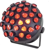
LED MOVING HEAD 100W
WITH DUAL PRISM & LIGHT RING
LYRE A LED 100W
AVEC DOUBLE PRISME & ANNEAU LUMINEUX
LED MOVING HEAD 100W
MIT DOPPELPRISMA & LICHTRING
LED MOVING HEAD 100W
MET DUAL PRISMA & LICHT RING
GB - User Manual - p. 9
UNPACKING INSTRUCTIONS
Immediately upon receiving a fixture, carefully unpack the carton, check the contents to ensure that all parts are present and have been received in good condition. Notify the freight company immediately and retain packing material for inspection if any parts appear to be damaged from shipping or the carton itself shows signs of mishandling. Keep the carton and all packing materials. In the event that a fixture must be returned to the factory, it is important that the fixture be returned in the original factory box and packing.
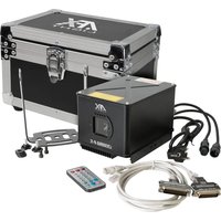
CONTENTS OF THE CARTON
- 1 x LED light effect
- 2x omega clamp
- 1x Powercon cable
- 1x DMX lead
- 1x User Manual
EXPLANATION OF SYMBOLS ON THE SILKSCREEN
The triangle containing a lightning symbol is used to indicate whenever your health is at risk (due to electrocution, for example).
CAUTION DO NOT OPEN THE HOUSING SHOCK HAZARD
An exclamation mark in a triangle indicates particular risks in handling or operating the appliance.
UK The unit complies with UK standards
For indoor use only
Minimum distance between the appliance and other objects
Don't stare into the light beam

IMPORTANT NOTE: Electric products must not be put into household waste. Please bring them to a recycling centre. Ask your local authorities or your dealer about the way to proceed.
Please read this manual carefully before operating this product.
SAFETY RECOMMENDATIONS
- Please read these instructions carefully, they include important information about the installation, usage and maintenance of this product.
- Please keep this User Guide for future reference. If you sell the unit to another user, be sure that he also receives this instruction booklet.
- Always make sure that you are connecting to the proper voltage, and that the line voltage you are connecting to is not higher than that stated on the bottom of the fixture.
The appliance is part of class I and must exclusively connected to an earthed mains outlet. - This product is intended for indoor use only!
- To prevent risk of fire or shock, do not expose fixture to rain or moisture. Make sure there are no flammable materials close to the unit while operating.
- The unit must be installed in a location with adequate ventilation, at least 20in (50cm) from adjacent surfaces. Be sure that no ventilation slots are blocked.
The minimum distance luminaire from that part of the luminaire or lamp to the lighted object is 0.5m - The max. ambient temperature (Ta) is 40^ . Don't operate the fixture at higher temperatures.
-
The surface temperature of the unit may reach up to 85^ . DO NOT TOUCH the housing bare-hand during its operation. Turn off the power and allow about 15 minutes for the unit to cool down before replacing or servicing.
DO NOT OPEN the unit within 5 minutes after switching off. -
In the event of a serious operating problem, stop using the unit immediately. Never try to repair the unit by yourself. Repairs carried out by unskilled people can lead to damage or malfunction. Please contact the nearest authorized technical assistance center. Always use the same type of spare parts.
- Make sure the power cord is never crimped or damaged.
- Never disconnect the power cord by pulling or tugging on the cord.
- Avoid direct eye exposure to the light source while it is on as sensitive persons may suffer an epileptic shock (especially meant for epileptics)!
The product is for decorative purposes only and not suitable as a household room illumination. - If the external flexible cable or cord of this luminaire is damaged, it shall be exclusively replaced by the manufacturer or his service agent or a similar qualified person in order to avoid a hazard.
- The lenses, housing or ultraviolet filter must be replaced if they are visibly damaged.
- The light source of this device is not replaceable. If it is defective, the entire unit must be discarded.
DISCONNECT DEVICE
Where the MAINS plug or an appliance coupler is used as the disconnect device, the disconnect device shall remain readily operable.
FEATURES
- 1 x 100W LED
- 28 × 0.2W RGB SMD LEDs for the light ring
- DMX, master-slave, sound-controlled and auto operation
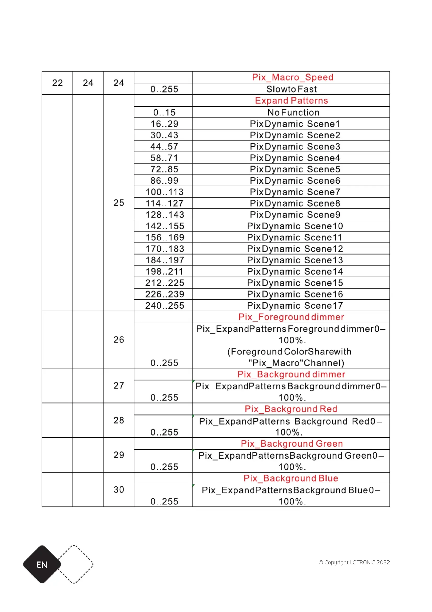
22/24/30 DMX channels - "Totem" mode
1 colour wheel with 11 colours + open
1 static gobo wheel with 14 gobo's + open
Gobo shake - High precision optics with 2^ projection angle
Electric focus over 2-3m
16- 24-facet prism with adjustable speed and direction - Smooth, accurate 8/16 bit PAN/TILT with inversion
- Scan position memory with auto repositioning after an incident
- Rainbow effect with adjustable direction and speed
- Linear dimmer
- 25x/sec high speed LED shutter/strobe effect with variable speed
- Preset variable/random strobe and dimming pulse effect
1.8" TFT LCD display
Fan cooling - Management system with constant temperature readout
- Mounting via 2 omega clamps & safety eyelet
FUSE REPLACEMENT
Disconnect the power cord before replacing a fuse and always replace with the same type fuse.
With a screwdriver wedge the fuse holder out of its housing.
Remove the damaged fuse from its holder and replace with exactly the same type of fuse.
Insert the fuse holder back in its place and reconnect power.
Warning: If after replacing the fuse you continue to blow fuses, STOP using the unit. Contact customer support for further instructions. Continuing to use the unit may cause serious damage.
CONTROL CONNECTION (FIG4)
Connect the provided XLR cable to the 3-pin XLR output of your controller and the other side to the male 3-pin XLR input of the moving head. You can chain multiple moving heads together through serial linking. The cable needed should be 2-core, screened cable with XLR input and output connectors. Please refer to diagram 4.
DMX512 CONNECTION WITH DMX TERMINATOR
For installations where the DMX cable has to run a long distance or is in an electrically noisy environment, such as in a discotheque, it is recommended to use a DMX termiantor. This helps in preventing corruption of the digital control signal by electrical noise. The DMX terminaotr is simply an XLR plug with a resistor connected between pins 2 and 3 which is then plugged into the output XLR socket of the last fixture in the chain. Please refer to diagram 4.
INSTALLATION (FIG.3)
The unit should be mounted via its screw holes on the bracket. Always ensure that the unit is firmly fixed to avoid vibration and slipping while operating. Always ensure that the structure to which you are attaching the unit is secure and is able to support a weight of 10 times of the unit's weight.
The installation must always be secured with a secondary safety attachment, e.g. an appropriate safety rope. Never stand directly below the device when mounting, removing or servicing the fixture. This fixture may be mounted in any position provided there is adequate room for ventilation.
The LED moving head provides a unique mounting bracket assembly that integrates the bottom of the base, the included 'omega bracket' and the safety cable rigging point in one unit (see illustration 3). When mounting this fixture on a truss, be sure to use an appropriate clamp with the included omega bracket using a M10 screw fitted through the center hole of the 'omega bracket'. As an added safety measure, be sure to attach at least one properly rated safety cable to the fixture using one of the safety cable rigging points integrated in the base assembly.
POWERLINK
Connect an IEC cable from the POWER OUT connector of the 1st unit to the POWER IN connector of the second unit, etc.
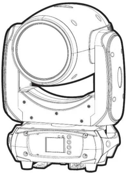
CONTROL PANEL (FIG. 2)
To access the main menu press the MENU button. Press the UP or DOWN buttons until you reach function you wish to change. When you reach the function you wish to change, press the ENTER button. When a function is selected, use the UP or DOWN buttons to change the function settings. Once your changes are made, press the ENTER button.
Tip: Press UP & DOWN buttons at the same time for 3 seconds. The display will reverse.
FUNCTION MENU
| MENU DESCRIPTION | ||||
| DMX Mode | DMX address A001-AXXX DMX address setting | |||
| Channel Mode | 22CH 22 channel mode | |||
| 24CH 24 channel mode | ||||
| 30CH 30 channel mode | ||||
| Auto run | Internal pro-gram 1-9 | Master/Alone Auto run | ||
| Music run | Internal pro-gram 1-9 | Master/Alone Sound control | ||
| SET | Reset Default Yes/No Reset default | |||
| Signal set Wire | Wired | |||
| Reverse Pan | (on/off) | Reverse Pan | ||
| Reverse Tilt | (on/off) | Reverse Tilt | ||
| Select Pan | 630/540/360 | Select Pan | ||
| Select Tilt | 270/180/90 | Select Tilt | ||
| Mic sensitivity 0-99%OFF signal mode (On/Off) | Mic sensitivityOff at original status and ON at re-set statusScan quick modeTotem mode | |||
| Scan quick modeTOTem mode OFF/CEN./R/L | ||||
| Manu | Reset | Total resetPan/Tilt resetColour resetGobo resetThe others Reset | Reset AllSeset Pan/TiltReset ColourReset goboReset the others | |
| Channel PAN=XXX... Channel control | ||||
| ADV (Ad- vanced) (Access code 0888) | Calibration UID code | PAN=XXX...XX XX XX XX X XX XX | Calibration UID code | |
CLEANING
Due to fog residue, smoke, and dust cleaning the internal and external lenses should be carried out periodically to optimize light output.
- Clean regularly the air vents and fans.
- Use normal glass cleaner and a soft cloth to wipe down the out-side casing.
- Clean the external optics with glass cleaner and a soft cloth every 20 days.
- Always be sure to dry all parts completely before plugging the unit back in.
SPECIFICATIONS
Power supply 90-260V~50/60Hz
Consumption 150W
PAN 360°/540°/630°
TILT. 90^ / 180^ / 270^
Focus 2-3m
Signal In/out 3-pin DMX
Power in/out . Powercon
Protection index IP20
Dimensions 299 x 184 x 423mm
Weight 10kg
MANUEL D'UTILISATION
DEBALLAGE
DISPOSITIF DE COUPURE
REEMPLACEMENT DU FUSIBLE
INSTALLATION (FIG. 3)
View the item on our website