
9BEAM-FX - Lighting AFX - Free user manual and instructions
Find the device manual for free 9BEAM-FX AFX in PDF.

| Product type | Spider lighting effect |
| Brand | AFX |
| Model | 9BEAM-FX |
| Power supply | 100-240V~50/60Hz |
| LED | 9 x 12W RGBW LED CREE |
| LED lifespan | >50,000 hours |
| DMX channels | 13 or 44 channels |
| Operating modes | Standalone, DMX, Master-Slave, Demo |
| Control | DMX512, Audio (built-in microphone) |
| Effects | Pulse, Strobe, electronic dimmer 0-100% |
| Mounting | Wall, truss, or floor |
| Max ambient temperature | 40°C |
| Minimum safety distance | 50 cm from surfaces |
| Max continuous operation time | 8 hours |
| Protection class | Class I (grounded plug) |
| Safety cable | Included (2 ropes) |
| Omega brackets | 2 included |
| Package contents | Device, power cord, XLR cord, 2 omega brackets, 2 safety ropes, user manual |
| Maintenance | Clean lenses every 3 weeks with glass cleaner and soft cloth |
| Safety | Do not open housing, do not look directly into light, indoor use only |
| Repairability | LED not replaceable, fuse replaceable |
| General information | CE compliant, indoor use only |
Frequently Asked Questions - 9BEAM-FX AFX
User questions about 9BEAM-FX AFX
0 question about this device. Answer the ones you know or ask your own.
Ask a new question about this device
Download the instructions for your Lighting in PDF format for free! Find your manual 9BEAM-FX - AFX and take your electronic device back in hand. On this page are published all the documents necessary for the use of your device. 9BEAM-FX by AFX.
USER MANUAL 9BEAM-FX AFX
UNPACKING INSTRUCTIONS
Immediately upon receiving a fi xture, carefully unpack the carton, check the contents to ensure that all parts are present and have been received in good condition. Notify the freight company immediately and retain packing material for inspection if any parts appear to be damaged from shipping or the carton itself shows signs of mishandling. Keep the carton and all packing materials. In the event that a fi xture must be returned to the factory, it is important that the fi xture be returned in the original factory box and packing.
CONTENTS OF THE CARTON
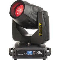
- 1 x Spider light effect
- 1x Mains lead
- 1x XLR lead
- 2x omega clamps
- 2x safety ropes
- 1x User Manual
EXPLANATION OF SYMBOLS ON THE SILKSCREEN

The triangle containing a lightning symbol is used to indicate whenever your health is at risk (due to electrocution, for example).

An exclamation mark in a triangle indicates particular risks in handling or operating the appliance.

The unit complies with CE standards

Class I protection: Connect only to an earthed mains outlet

For indoor use only

Minimum distance between the appliance and other objects

Don't stare into the light beam

CAUTION DO NOT OPEN THE HOUSING SHOCK HAZARD
Please read this manual carefully before operating this product.
SAFETY RECOMMENDATIONS
- Please read these instructions carefully, they include important information about the installation, usage and maintenance of this product.
- Please keep this User Guide for future reference. If you sell the unit to another user, be sure that he also receives this instruction booklet.
- Always make sure that you are connecting to the proper voltage, and that the line voltage you are connecting to is not higher than that stated on the bottom of the fixture.
- The appliance is part of class I and must exclusively connected to an earthed mains outlet.
- This product is intended for indoor use only!
- To prevent risk of fire or shock, do not expose fixture to rain or moisture. Make sure there are no flammable materials close to the unit while operating.
- The unit must be installed in a location with adequate ventilation, at least 20in (50cm) from adjacent surfaces. Be sure that no ventilation slots are blocked.
-
The minimum distance luminaire from that part of the luminaire or lamp to the lighted object is 0.5m.
-
The max. ambient temperature (Ta) is 40^ . Don't operate the fixture at higher temperatures.
- In the event of a serious operating problem, stop using the unit immediately. Never try to repair the unit by yourself. Repairs carried out by unskilled people can lead to damage or malfunction. Please contact the nearest authorized technical assistance center. Always use the same type of spare parts.
- Make sure the power cord is never crimped or damaged.
- Never disconnect the power cord by pulling or tugging on the cord.
- Avoid direct eye exposure to the light source while it is on as sensitive persons may suffer an epileptic shock (especially meant for epileptics)!
- The product is for decorative purposes only and not suitable as a household room illumination.
- If the external flexible cable or cord of this luminaire is damaged, it shall be exclusively replaced by the manufacturer or his service agent or a similar qualified person in order to avoid a hazard.
- The lenses, housing or ultraviolet filter must be replaced if they are visibly damaged.
- The light source of this device is not replaceable. If it is defective, the entire unit must be discarded.
DISCONNECT DEVICE
Where the MAINS plug or an appliance coupler is used as the disconnect device, the disconnect device shall remain readily operable.
FEATURES
• 13 / 44 DMX channels
- 9x 12W RGBW LED
• Extra long life CREE LEDs (>50,000 h)
- 3 x 3 zones
- Narrow beams
- DMX, stand-alone, master-slave and show modes
• Built-in music controlled programs
- Pulse & Strobe effects
• Electronic dimmer 0-100%
- Suitable for wall, truss or floor mounting
INSTALLATION
The unit should be mounted via its screw holes on the bracket. Always ensure that the unit is firmly fixed to avoid vibration and slipping while operating. Always ensure that the structure to which you are attaching the unit is secure and is able to support a weight of 10 times of the unit's weight.
The installation must always be secured with a secondary safety attachment, e.g. an appropriate safety rope.
Never stand directly below the device when mounting, removing or servicing the fixture.
ORIENTATION
This fixture may be mounted in any position provided there is adequate room for ventilation.
RIGGING
The LED moving head provides a unique mounting bracket assembly that integrates the bottom of the base, the included 'omega bracket' and the safety cable rigging point in one unit (see illustration). When mounting this fixture on a truss, be sure to use an appropriate
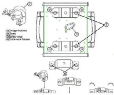
clamp with the included omega bracket using a M10 screw fitted through the center hole of the 'omega bracket'. As an added safety measure, be sure to attach at least one properly rated safety cable to the fixture using one of the safety cable rigging points integrated in the base assembly.
FUSE REPLACEMENT
Disconnect the power cord before replacing a fuse and always replace with the same type fuse. With a screwdriver wedge the fuse holder out of its housing.
Remove the damaged fuse from its holder and replace with exactly the same type of fuse.
Insert the fuse holder back in its place and reconnect power.
Warning: If after replacing the fuse you continue to blow fuses, STOP using the unit. Contact customer support for further instructions. Continuing to use the unit may cause serious damage.
FIXTURE LINKING
You will need a serial data link to run light shows of one or more fixtures using a DMX-512 controller or to run synchronized shows on two or more fixtures set to a master/slave operating mode. The combined number of channels required by all fixtures on a serial data link determines the number of fixtures that the data link can support.
Important: Fixtures on a serial/data link must be daisy chained in one single line. Maximum recommended serial data link distance: 100 meters.
Data Cabling
To link fixtures together you must use data cables. If you choose to create your own cable, please use data-grade cables that can carry a high quality signal and are less prone to electromagnetic interference.
CABLE CONNECTORS
Cabling must have a male XLR connector on one end and a female XLR connector on the other end.
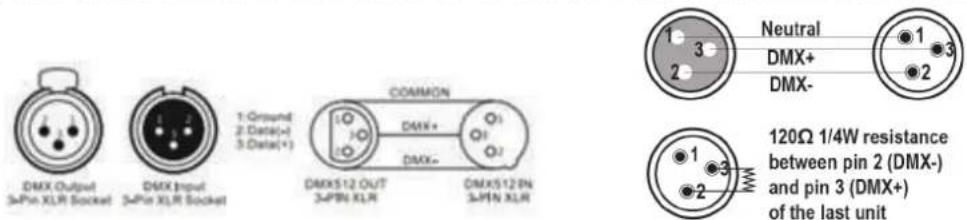
DMX connector configuration
Termination reduces signal errors. To avoid signal transmission problems and interference, it is always advisable to connect a DMX signal terminator.
POWER LINK
You can power up to 5 units via the POWER IN/POWER OUT connectors from one single mains outlet. Connect a POWERCON cable from the POWER OUT connector of the 1st unit to the POWER IN connector of the second unit, etc.
Setting up a DMX Serial Data Link
- Connect the (male) 3 pin connector side of the DMX cable to the output (female) 3 pin connector of the controller.
- Connect the end of the cable coming from the controller which will have a (female) 3 pin connector to the input connector of the next fixture consisting of a (male) 3 pin connector.
- Then, proceed to connect from the output as stated above to the input of the following fixture and so on.
Master/Slave Fixture Linking
-
Connect the (male) 3 pin connector side of the DMX cable to the output (female) 3 pin connector of the first fixture.
-
Connect the end of the cable coming from the first fixture which will have a (female) 3 pin connector to the input connector of the next fixture
-
Connect the (male) 3 pin connector side of the DMX cable to the output (female) 3 pin connector of the first fixture.
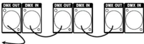
- Connect the end of the cable coming from the first fixture which will have a (female) 3 pin connector to the input connector of the next fixture
flowchart
graph LR
    A["DMX OUT"] --> B["DMX IN"]
    B --> C["DMX OUT"]
    C --> D["DMX IN"]
    D --> E["DMX OUT"]
    E --> F["DMX IN"]
consisting of a (male) 3 pin connector. Then, proceed to connect from the output as stated above to the input of the following fixture and so on.
Often, the set up for Master-Slave and Stand-alone operation requires that the first fixture in the chain be initialized for this purpose via either settings in the control panel or DIP-switches. Secondly, the fixtures that follow may also require a slave setting. Please consult the "Operating Instructions" section in this manual for complete instructions for this type of setup and configuration.
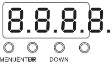
CONTROL PANEL
To access the main menu press the MENU button. Press the UP or DOWN buttons until you reach function you wish to change. When you reach the function you wish to change, press the ENTER button. When a function is selected, use the UP or DOWN buttons to change the function settings. Once your changes are made, press the ENTER button.
FUNCTION MENU
| DMX Address A001---A512 | |
| Channel Mode 13 ch, 44ch | |
| Show Mode Sound, Auto | |
| Slave Mode Master, Slave | |
| Black Out YES, NO | |
| Sound State ON, OFF | |
| Sound Sense 0 -100 off - the most sensitive | |
| Pan Inverse | YES, NO |
| Tilt1Inverse | YES, NO |
| Tilt2Inverse | YES, NO |
| Tilt3Inverse | YES, NO |
| Back Light | On, Off |
| Auto Test Automatic test | |
| Fixture Time | 0----9999 |
| Firmware Version | V104 |
| Defaults | YES,NO |
| System Reset | YES,NO |
FUNCTION MODE
DMX address setting
With this function, you can adjust the desired DMX-address via the Control Board.
- Press the either the MENU, UP or DOWN buttons until "ADDR" is displayed, press ENTER.
- The current address will now be displayed and flashing. Press the UP or DOWN buttons to find your desired address. Press ENTER to set your desired DMX address.
Channel Mode: The unit has 13 or 44 channels that can receive the International DMX signal.
Show Mode: The user can select between [Sound] and [Auto] mode
Slave Mode: In [Slave] mode, you can chose [Master] mode and [Slave] mode.
Black Out: Select [YES] or [NO] to black out or not
Sound State: Sound control [ON] or [OFF]
Sound sensitivity
In this Mode a number between 0-100 will be displayed. Press the UP or DOWN buttons to adjust the sound sensitivity, 0 being the least sensitive and 100 being the most sensitive.
Pan Reverse: Reverse the Pan-movement.
Tilt 1 Reverse: Reverse the Tilt 1-movement.
Tilt 2 Reverse: Reverse the Tilt 2-movement.
Tilt 3 Reverse: Reverse the Tilt 3-movement.
Back Light: Turns the LED display back light on or off
Auto Test: The unit makes a self test.
Fixture Time ---0-9999: With this function you can display the running time of the unit.
Firmware Version ---V104: Displays the software version of the unit
Default: Restore to factory setting [YES] or [NO]
5.17 System Reset : System reset [YES] or [NO]
HOW TO OPERATE MOTOR OFFSET FUNCTION:
Press "MENU" button, then press "ENTER" for 3 seconds at least, when the interface shows "Pan Offset"(X motor fine adjust), press button "Ok" to set motor position from value -127....127, then Press button "Ok" to save.
CLEANING
Due to fog residue, smoke, and dust cleaning the internal and external lenses should be carried out periodically to optimize light output.
- Clean regularly the air vents and fans.
- Use normal glass cleaner and a soft cloth to wipe down the out-side casing.
- Clean the external optics with glass cleaner and a soft cloth every 20 days.
• Always be sure to dry all parts completely before plugging the unit back in.
SPECIFICATIONS
Power supply 100-240V\~50/60Hz
Consumption 140W max.
Fuse 3A
Light source 9x 12W RGBW CREE LED
Tilt....0-185°
Pan 0-360°
Beam angle 5°
Dimensions 458 x 429 x 208mm
Weight 10.6kg

IMPORTANT NOTE: Electric products must not be put into household waste. Please bring them to a recycling centre. Ask your local authorities or your dealer about the way to proceed.
MANUEL D'UTILISATION
DÉBALLAGE
DISPOSITIF DE COUPURE
Consommation....140W max.
Fusible 3A
Source lumineuse....9 LED RGBW CREE de 12W chacune
Tilt 0-185°
Pan 0-360°
Angle de projection 5°
Dimensions 458 x 429 x 208mm
Poids 10,6kg

RIGGING
Black Out: Kies [YES] of [NO]
Sound State: Geluidsbesturing [ON] of [OFF]
MANUAL DE INSTRUÇÕES
INSTRUÇÕES PARA DESEMBALAR
natural_image
Close-up of a black rectangular object with a dashed white line extending from its edge (no text or symbols)

View the item on our website
- UNPACKING INSTRUCTIONS
- CONTENTS OF THE CARTON
- EXPLANATION OF SYMBOLS ON THE SILKSCREEN
- CAUTION DO NOT OPEN THE HOUSING SHOCK HAZARD
- SAFETY RECOMMENDATIONS
- DISCONNECT DEVICE
- FEATURES
- INSTALLATION
- ORIENTATION
- RIGGING
- FUSE REPLACEMENT
- FIXTURE LINKING
- Data Cabling
- CABLE CONNECTORS
- DMX connector configuration
- POWER LINK
- Setting up a DMX Serial Data Link
- Master/Slave Fixture Linking
- CONTROL PANEL
- FUNCTION MODE
- DMX address setting
- Sound sensitivity
- HOW TO OPERATE MOTOR OFFSET FUNCTION:
- CLEANING
- SPECIFICATIONS
- MANUEL D'UTILISATION
- DÉBALLAGE
- DISPOSITIF DE COUPURE
- MANUAL DE INSTRUÇÕES
- INSTRUÇÕES PARA DESEMBALAR
Brand : AFX
Model : 9BEAM-FX
Category : Lighting