CHASER-MOVING-BAR - Lighting AFX - Free user manual and instructions
Find the device manual for free CHASER-MOVING-BAR AFX in PDF.

User questions about CHASER-MOVING-BAR AFX
0 question about this device. Answer the ones you know or ask your own.
Ask a new question about this device
Download the instructions for your Lighting in PDF format for free! Find your manual CHASER-MOVING-BAR - AFX and take your electronic device back in hand. On this page are published all the documents necessary for the use of your device. CHASER-MOVING-BAR by AFX.
USER MANUAL CHASER-MOVING-BAR AFX
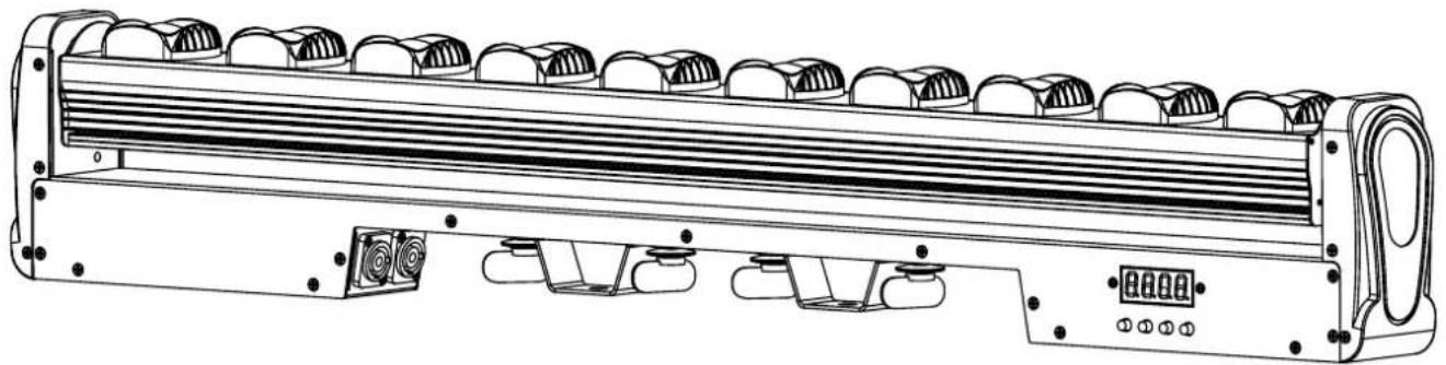
RGBW BEAM BAR WITH TILT
BARRE A LED RGBW AVEC TILT
RGBW BEAM LICHTBALKEN MIT TILT
RGBW BEAM LICHTBALK MET TILT
BARRA DE LED RGBW CON MOVIMIENTO TILT

Download the manual in other languages
Mode Effect Chart - p. 4-7
GB - User Manual - p. 8
| CH CH Value Basic function | |
| 1 000-255 Y-axis motor | |
| 2 000-255 Y-axis motor speed | |
| 3 000-255 Linear dimming of red lamp beads. | |
| 4 000-255 Linear dimming of green lamp beads. | |
| 5 000-255 Linear dimming of blue lamp beads. | |
| 6 000-255 Linear dimming of white lamp beads. | |
| 7 000-255 Reset: When the parameter value is 150-255, the whole machine is reset. The parameter value of the console must be pulled below 10 first, and then pushed to 150-255 to be useful. The parameter value of 000-149 is useless and cannot be reset. |
CH13 CHANNEL CHART
| CH CH Value Basic function | |
| 1 000-255 Y-axis motor | |
| 2 000-255 Y-axis motor speed | |
| 3 000-255 Total dimming | |
| 4 000-255 Strobe | |
| 5 000-255 Linear dimming of red lamp beads. | |
| 6 000-255 Linear dimming of green lamp beads. | |
| 7 000-255 Linear dimming of blue lamp beads. | |
| 8 000-255 Linear dimming of white lamp beads. | |
| 9 000-255 Mode | |
| 10 000-255 Speed | |
| 11 000-255 background color | |
| 12 000-255 background color dimming | |
| 13 000-255 Reset: When the parameter value is 150-255, the whole machine is reset. The parameter value of the console must be pulled below 10 first, and then pushed to 150-255 to be useful. The parameter value of 000-149 is useless and cannot be reset. |
CH43 CHANNEL CHART
| CH CH Value Basic function | |
| 1 000-255 Y-axis motor | |
| 2 000-255 Y-axis motor speed | |
| 3 000-255 The 1st red lamp bead linear dimming. | |
| 4 000-255 The 1st green lamp bead linear dimming. | |
| 5 000-255 The 1st blue lamp bead linear dimming. | |
| 6 000-255 The 1st white lamp bead linear dimming. | |
| ... | |
| ... | |
| 39 000-255 The 10th red lamp bead linear dimming | |
| 40 000-255 The 10th green lamp bead linear dimming | |
| 41 000-255 The 10th blue lamp bead linear dimming | |
| 42 000-255 The 10th white lamp bead linear dimming | |
| 43 000-255 Reset: When the parameter value is 150-255, the whole machine is reset. The parameter value of the console must be pulled below 10 first, and then pushed to 150-255 to be useful. The parameter value of 000-149 is useless and cannot be reset. | |
MODE EFFECT chart
| CH Value | Mode code | Effect |
| 0-1 0 No effect | ||
| 2-3 1 R red light. | ||
| 4-5 2 G green light. | ||
| 6-7 3 B blue light. | ||
| 8-9 4 W white light. | ||
| 10-11 5 RG red and green dye lights. | ||
| 12-13 6 RB red and blue dye lights. | ||
| 14-15 7 GB green and blue dye lights. | ||
| 16-17 8 Comprehensive 1-7 effect loop. | ||
| 18-19 9 R a red light is running | ||
| 20-21 10 G a green light is running | ||
| 22-23 11 B a blue light is running | ||
| 24-25 12 W a white light is running | ||
| 26-27 13 RG a red and green dyed light is runnig | ||
| 28-29 14 RB a red and blue dyed light is runnig | ||
| 30-31 15 GB a green and blue dyed light is runnig | ||
| 32-33 16 Comprehensive 9-15 effect loop. | ||
| 34-35 17 R two red lights are running. | ||
| 36-37 18 G two green lights are running. | ||
| 38-39 19 B two blue lights are running. | ||
| 40-41 20 W two white lights are running. | ||
| 42-43 21 RG two red and green dyed lights are running | ||
| 44-45 22 RB two red and blue dyed lights are running | ||
| 46-47 23 GB two green and blue dyed lights are running | ||
| 48-49 24 Comprehensive 17-23 effect loop. | ||
| 50-51 25 R three red lights are running. | ||
| 52-53 26 G three green lights are running. | ||
| 54-55 27 B three blue lights are running. | ||
| 56-57 28 W three white lights are running. | ||
| 58-59 29 RG three red and green dyed lights are running | ||
| 60-61 30 RB three red and blue dyed lights are running | ||
| 62-63 31 GB three green and blue dyed lights are running | ||
| 64-65 32 Comprehensive 25-31 effect loop. | ||
| 66-67 33 R a red light refreshes. | ||
| 68-69 34 G a green light refreshes. | ||
| 70-71 35 B a blue light refreshes. | ||
| 72-73 36 W a white light refreshes. | ||
| 74-75 37 RG a red and green dyed light refreshes. | ||
| 76-77 38 RB a red and blue dyed light refreshes. | ||
78-79 39 GB a green and blue dyed light refreshes.
80-81 40 Comprehensive 33-39 effect loop.
82-83 41 R two red lights refresh.
84-85 42 G two green lights refresh.
86-87 43 B two blue lights refresh.
88-89 44 W two white lights refresh.
90-91 45 RG two red and green dyed light refreshes.
92-93 46 RB two red and blue dyed light refreshes.
94-95 47 GB two green and blue dyed light refreshes.
96-97 48 Comprehensive 41-47 effect loop.
98-99 49 R a red light runs back and forth.
100-101 50 G a green light runs back and forth.
102-103 51 B a blue light runs back and forth.
104-105 52 W a white light runs back and forth.
106-107 53 RG a red and green dyed light runs back and forth.
108-109 54 RB a red and blue dyed light runs back and forth.
110-111 55 GB a green and blue dyed light runs back and forth.
112-113 56 Comprehensive 49-55 effect loop.
114-115 57 R two red light runs back and forth.
116-117 58 G two green light runs back and forth.
118-119 59 B two blue light runs back and forth.
120-121 60 W two white light runs back and forth.
122-123 61 RG two red and green dyed light runs back and forth.
124-125 62 RB two red and blue dyed light runs back and forth.
126-127 63 GB two green and blue dyed light runs back and forth.
128-129 64 Comprehensive 57-63 effect loop.
130-131 65 R a red light at each end runs back and forth.
132-133 66 G a green light at each end runs back and forth.
134-135 67 B a blue light at each end runs back and forth.
136-137 68 W a white light at each end runs back and forth.
138-139 69 RG a red and green dyed light at each end runs back and forth.
140-141 70 RB a red and blue dyed light at each end runs back and forth.
142-143 71 GB a green and blue dyed light at each end runs back and forth.
144-145 72 Comprehensive 65-71 effect loop.
146-147 73 R two red light at each end runs back and forth.
148-149 74 G two green light at each end runs back and forth.
150-151 75 B two blue light at each end runs back and forth.
152-153 76 W two white light at each end runs back and forth.
154-155 77 RG two red and green dyed light at each end runs back and forth.
156-157 78 RB two red and blue dyed light at each end runs back and forth.
158-159 79 GB two green and blue dyed light at each end runs back and forth.
160-161 80 Comprehensive 72-79 effect loop.
| 162-163 81 R a red light refreshes back and forth. |
| 164-165 82 G a green light refreshes back and forth. |
| 166-167 83 B a blue light refreshes back and forth. |
| 168-169 84 W a white light refreshes back and forth. |
| 170-171 85 RG a red and green dyed light refreshes back and forth. |
| 172-173 86 RB a red and blue dyed light refreshes back and forth. |
| 174-175 87 GB a green and blue dyed light refreshes back and forth. |
| 176-177 88 Comprehensive 81-87 effect loop. |
| 178-179 89 R a red light running with afterimages. |
| 180-181 90 G a green light running with afterimages. |
| 182-183 91 B a blue light running with afterimages. |
| 184-185 92 W a white light running with afterimages. |
| 186-187 93 RG a red and green dyed light running with afterimages. |
| 188-189 94 RB a red and blue dyed light running with afterimages. |
| 190-191 95 GB a green and blue dyed light running with afterimages. |
| 192-193 96 Comprehensive 89-95 effect loop. |
| 194-195 97 R two red lights pendulums. |
| 196-197 98 G two green lights pendulums. |
| 198-199 99 B two blue lights pendulums. |
| 200-201 100 W two white lights pendulums. |
| 202-203 101 RG two red and green dyed lights pendulums. |
| 204-205 102 RB two red and blue dyed lights pendulums. |
| 206-207 103 GB two green and blue dyed lights pendulums. |
| 208-209 104 Comprehensive 97-103 effect loop. |
| 210-211 105 R a red light stacks up. |
| 212-213 106 G a green light stacks up. |
| 214-215 107 B a blue light stacks up. |
| 216-217 108 W a white light stacks up. |
| 218-219 109 RG a red and green dyed light stacks up. |
| 220-221 110 RB a red and blue dyed light stacks up. |
| 222-223 111 GB a green and blue dyed light stacks up. |
| 224-225 112 Comprehensive 105-111 effect loop. |
| 226-227 113 R a red light stacks up back and forth. |
| 228-229 114 G a green light stacks up back and forth. |
| 230-231 115 B a blue light stacks up back and forth. |
| 232-233 116 W a white light stacks up back and forth. |
| 234-235 117 RG a red and green dyed light stacks up back and forth. |
| 236-237 118 RB a red and blue dyed light stacks up back and forth. |
| 238-239 119 GB a green and blue dyed light stacks up back and forth. |
| 240-241 120 Comprehensive 113-119 effect loop. |
| 242-243 121 Colorful effect one. |
| 244-245 122 Colorful effect two. |
| 246-247 123 Colorful effect three. |
| 248-249 124 Red waves. |
| 250-251 125 Green waves. |
| 252-253 126 Blue waves. |
| 254-255 127 Mode code 9-126 cycle; after mode code 124, 125, 126, the colorful waves are finished. |
USER MANUAL
UNPACKING INSTRUCTIONS
Immediately upon receiving a fixture, carefully unpack the carton, check the contents to ensure that all parts are present and have been received in good condition. Notify the freight company immediately and retain packing material for inspection if any parts appear to be damaged from shipping or the carton itself shows signs of mishandling. Keep the carton and all packing materials. In the event that a fixture must be returned to the factory, it is important that the fixture be returned in the original factory box and packing.
CONTENTS OF THE CARTON
- 1 pc. CHASER-MOVING-BAR
- 1 pc. user manual
- 1 pc. power cable
EXPLANATION OF SYMBOLS ON THE SILKSCREEN

The triangle containing a lightning symbol is used to indicate whenever your health is at risk (due to electrocution, for example).

An exclamation mark in a triangle indicates particular risks in handling or operating the appliance.

Class I protection: Connect only to an earthed mains outlet

The unit complies with UK standards

For indoor use only

Minimum distance between the appliance and other objects

Do not stare into the light beam

CAUTION DO NOT OPEN THE HOUSING SHOCK HAZARD
Please read this manual carefully before operating this product.
SAFETY RECOMMENDATIONS
- Please read these instructions carefully, they include important information about the installation, usage and maintenance of this product.
- Please keep this User Guide for future reference. If you sell the unit to another user, be sure that he also receives this instruction booklet.
- Always make sure that you are connecting to the proper voltage, and that the line voltage you are connecting to is not higher than that stated on the bottom of the fixture.
- This product is intended for indoor use only!
- The appliance is part of class I and must exclusively connected to an earthed mains outlet.
- To prevent risk of fire or shock, do not expose fixture to rain or moisture. Make sure there are no flammable materials close to the unit while operating.
- The unit must be installed in a location with adequate ventilation, at least 20in (50cm) from adjacent surfaces. Be sure that no ventilation slots are blocked.
- The minimum distance luminaire from that part of the luminaire or lamp to the lighted object is 0.5 ~m .
- The max. ambient temperature (Ta) is 40^ . Don't operate the fixture at higher temperatures.
- The surface temperature of the unit may reach up to 85^ . DO NOT TOUCH the housing bare-hand during its operation. Turn off the power and allow about 15 minutes for the unit to cool down before replacing or servicing.
- DO NOT OPEN the unit within 5 minutes after switching off.
- In the event of a serious operating problem, stop using the unit immediately. Never try to repair
the unit by yourself. Repairs carried out by unskilled people can lead to damage or malfunction. Please contact the nearest authorized technical assistance center. Always use the same type of spare parts.
- Make sure the power cord is never crimped or damaged.
- Never disconnect the power cord by pulling or tugging on the cord.
- Avoid direct eye exposure to the light source while it is on as sensitive persons may suffer an epileptic shock (especially meant for epileptics)!
- The light source of this fixture is not replaceable. When the light source reaches its end of life, the whole fixture needs to be replaced. The product is not intended for household and domestic use.
- If the external flexible cable or cord of this luminaire is damaged, it shall be exclusively replaced by the manufacturer or his service agent or a similar qualified person in order to avoid a hazard
- The lenses, housing or ultraviolet filter must be replaced if they are visibly damaged.
DISCONNECT DEVICE
Where the MAINS plug or an appliance coupler is used as the disconnect device, the disconnect device shall remain readily operable.
INSTALLATION
The unit should be mounted via its screw holes on the bracket. Always ensure that the unit is firmly fixed to avoid vibration and slipping while operating. Always ensure that the structure to which you are attaching the unit is secure and is able to support a weight of 10 times of the unit's weight.
The installation must always be secured with a secondary safety attachment, e.g. an appropriate safety rope.
Never stand directly below the device when mounting, removing or servicing the fixture.
DMX CONNECTION
Connect an XLR cable to the male 3-pin XLR output of your controller and the other side to the female 3-pin XLR input of the light. You can chain multiple lights together through serial linking
The cable needed should be two core, screened cable with XLR input and output connectors.
DATA CABLING
To link fixtures together you must use data cables. If you choose to create your own cable, please use data-grade cables that can carry a high quality signal and are less prone to electromagnetic interference.
CABLE CONNECTORS
Cabling must have a male XLR connector on one end and a female XLR connector on the other end.
Termination reduces signal errors. To avoid signal transmission problems and interference, it is always advisable to connect a DMX signal terminator.
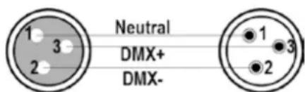
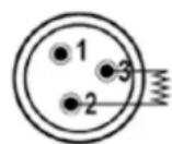
120Ω 1/4W resistance between pin 2 (DMX-) and pin 3 (DMX+) of the last unit
CAUTION
Do not allow contact between the common and the fixture's chassis ground. Grounding the common can cause a ground loop, and
your fixture may perform erratically. Test cables with an ohm meter to check correct polarity and to make sure the pins are not grounded or shorted to the shield or each other.
CONTROL PANEL
To access the main menu press the MENU button. Press the UP or DOWN buttons until you reach function you wish to change. When you reach the function you wish to change, press the ENTER button. When a function is selected, use the UP or DOWN buttons to change the function settings. Once your changes are made, press the ENTER button.
MENU
After power on, press the MENU key, and the menu function table will appear in sequence; press the UP or DOWN key to change the values, and press ENTER to save the current functions and parameters (after saving, it has a power-down memory).
FUNCTION TABLE
| A001-A512 Set | the address code, change the address code (A001~A512) up or down, and press ENTER to save. |
| CH7-CH43 Switch CH7, CH13, CH43 up or down, and press ENTER to save. | |
| M000-M126 | 127 kinds of built-in effects, change the built-in effects up or down, and press the ENTER key to save. |
| S000-S255 Change the running speed of the built-in effect (S000~S255) up or down, and press ENTER to save. | |
| R255-R000 Change the brightness of the red lamp beads up or down (R000~R255), and press the ENTER key to save. | |
| G255-G000 Change the brightness of the green lamp beads up or down (G000~G255), and press the ENTER key to save. | |
| B255-B000 Change the brightness of the blue lamp beads up or down (B000~B255), and press the ENTER key to save. | |
| W255-W000 Change the brightness of the white lamp beads up or down (W000~W255), and press the ENTER key to save. | |
| Soud Sound control mode | |
| M000-M255 Adjust the Y-axis motor parameters (M000~M255) up or down, and press ENTER to save. | |
| T000 Display temperature, such as T045, it means the current lamp temperature is 45°C; if 10K thermistor is not installed, it will display T000. | |
MASTER-SLAVE CONTROL
Two or more identical fixtures are connected via DMX three-core signal cable. All fixtures are set to any address code from A001~A512, the first fixtures is set as the master, and the other ones are slaves. Adjust the gradient, pulse change, jump, etc. on the master fixture. All slave fixtures will work like the master fixture.
Special attention:
- Only one fixture can be set for a group of fixtures. If there are multiple master fixtures, all fixtures will flash randomly without synchronization.
- All fixtures must be used only when the DMX512 console is turned off.
FACTORY SETTING
In any mode, press the MENU key for 5 seconds to enter the factory setting. The factory settings are mainly the output power of each channel, the fan setting mode, the setting of the thermal protection point, and the function of sending parameters. Press the menu button for 5 seconds to exit.
FACTORY SETTINGS
| R255-R032 Change the red LED current (R032-R255) up or down, and press ENTER to save. | |
| G255-G032 Change the green LED current (G032-G255) up or down, and press ENTER to save. | |
| B255-B032 Change the blue LED current (B032-B255) up or down, and press ENTER to save. | |
| W255-W032 Change the white LED current (W032-W255) up or down, and press ENTER to save. | |
| M000-M255 | Change the Y-axis motor running speed (M000~M255) up or down, and press EN-TER to save. |
| FAN0-FAN1 Fan setting: FAN0 will start the fan when it is powered on, FAN1 will start the fan when it reaches the set temperature protection point, and press ENTER to save. | |
| T040-T070 Change the temperature parameter up or down (40°~70°), press the enter ENTER to save. | |
| Send Send the factory setting parameters of the machine up or down to all other lamps connected in parallel with three-core signal lines; confirm the sending parameters and press the menu key for 5 seconds to exit, or deny the parameters and press the ENTER key to cancel the sending. | |
DMX512 CONSOLE
After power on, set the address codes of all fixtures, and then connect all fixtures in parallel to the DMX512 console via three-core signal cables. The address codes will stop flashing, indicating that the DMX512 console signal has been sent to the fixtures. Use DMX512 to control the fixtures.
See the DMX channel charts on page 2-3 of the manual.
MODE EFFECT
See the MODE channel chart on page 3-6 of the manual.
Tip: Mode code 9~120, you can push and pull RGBW to change the background color.
SPECIFICATIONS
Input voltage 100-240V~50/60Hz
Consumption 180W
Light source 10x 15W RGBW 4-in-1 LEDs
Operating modes. DMX512, auto, master-slave, RDM
DMX channels 7/13/43
Dimmer Linear 0-100% 32bit
Strobe frequency 1\~30Hz
IP IP20
Dimensions 980 x 180 x 80mm
Weight 6.1kg

IMPORTANT NOTE: Electric products must not be put into household waste. Please bring them to a recycling centre. Ask your local authorities or your dealer about the way to proceed.
MANUEL D'UTILISATION
DEBALLAGE
DISPOSITIF DE COUPURE
Dimmer Linear 0-100% 32bit.
Stroboskop-Frequency 1\~30Hz
Schutzfaktor IP20
Abmessungen 980 x 180 x 80mm
Gewicht 6.1kg

To access the main menu press the MENU button. Press the UP or DOWN buttons until you reach function you wish to change. When you reach the function you wish to change, press the
ENTER button. When a function is selected, use the UP or DOWN buttons to change the function settings. Once your changes are made, press the ENTER button.
MENU
Lichtbron 10x15W4-in-1 RGBW LED's
Download the manual in other languages