DA12 - Hand tool MSW - Free user manual and instructions
Find the device manual for free DA12 MSW in PDF.



User questions about DA12 MSW
0 question about this device. Answer the ones you know or ask your own.
Ask a new question about this device
Download the instructions for your Hand tool in PDF format for free! Find your manual DA12 - MSW and take your electronic device back in hand. On this page are published all the documents necessary for the use of your device. DA12 by MSW.
USER MANUAL DA12 MSW
natural_image
Technical line drawing of a mechanical clamp or lever device with no visible text or symbolsExpondo GmbH
Köpenicker Str. 54
10179 Berlin
Deutschland
text_image
Technical diagram of a spray gun assembly with numbered parts and component layouts for each part.natural_image
Line drawing of a handheld electric tool with nozzle and handle (no text or symbols)natural_image
Diagram showing a mechanical component with a blue arrow indicating direction, no text or symbols presentnatural_image
Diagram of a mechanical device with a lever and a blue upward arrow indicating motion (no text or symbols)natural_image
Mechanical assembly diagram showing a lever mechanism with three base plates and a central gear (no text or symbols)natural_image
Mechanical clamp device with two shafts and a spring base, showing rotational motion arrows (no text or symbols)natural_image
Illustration of a hammer striking a screw with a blue arrow indicating the process (no text or symbols present)text_image
Labeled diagram of various hair tools and accessories, including a spray gun, tool holder, and electrical plug.natural_image
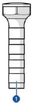
Illustration of a bolt with a numbered marker (1) pointing to the bottom section, no text or symbols present.
text_image
Diagram showing nine labeled stages of a laboratory bottle or pipette with numbered callouts pointing to each stage.text_image
Diagram showing 19 circular patterns with numbered labels, likely illustrating a pattern or design concept.| Teil | Artikelnummer |
| 1. Pilz 47,5 x 32,6 mm | N840021 |
| 2. Pilz 40 x 27,1 mm | N840022 |
| 3. Pilz 32,9 x 22,3 mm | N840023 |
| 4. Pilz 39,61 x 24,8 mm | N840034 |
| 5. Pilz 29,3 x 19,7 mm | N840030 |
| 6. Pilz 31,7 x 16,6 mm | N840024 |
| 7. Pilz 25,9 mm | N840032 |
| 8. Pilz 20,8 mm | N840031 |
| 9. Pilz 15,9 mm | N840033 |
| 10. Pilz 15,2 mm | N840015 |
| 11. Pilz 19,8 mm | N840016 |
| 12. Pilz 24,6 mm | N840017 |
| 13. Pilz 31,6 mm | N840018 |
| 14. Pilz 35,1 mm | N840019 |
| 15. Pilz 40,2 mm | N840020 |
| 16. Pilz 32 mm | N840035 |
| 17. Pilz 28 mm | N840036 |
| 18. Pilz 22 mm | N840037 |
| 19. Pilz 16 mm | N840038 |
9. Fehlerbehebung
natural_image
Technical line drawing of a mechanical clamp or lever device with no visible text or symbolsExpondo GmbH
Köpenicker Str. 54
10179 Berlin
Germany
EN – Original language
V00_01-12/2021
Table of contents
1. Introduction....3
1.1. About this document....3
1.2. Languages....3
2. Product .... 3
2.1. Intended use....3
2.2. Foreseeable misuse .. 3
2.3. Disclaimer....3
2.4. General specifications .. 3
2.5. Type plates . 4
2.5.1. 10061540....4
2.5.2. 10061541 4
2.5.3. 10061542....4
3. Description and operation....5
3.1. Main parts 5
4. Safety 6
4.1. Personal protective equipment 6
4.2. Symbols on the product or packaging....6
4.3. Safety instructions .. 6
4.3.1. General safety instructions 6
4.3.2. Transport and storage .. 7
4.3.3. Installation .. 7
4.3.4. Use 7
4.3.5. Maintenance .. 7
4.3.6. Children and disabled .. 8
5. Storage....8
6. Installation 8
6.1. Package contents....8
6.1.1. 10061540....8
6.1.2. 10061541....8
6.1.3. 10061542 & 10061543....9
6.2. Requirements for the location of installation....9
7. Use 9
7.1. Before use....9
7.2. Switching on and starting up 9
7.3. Using the product .. 10
7.3.1. Using the dent removal tabs 10
7.3.2. Using the knock down tips 13
7.4. Switching off .. 13
8. Maintenance....13
8.1. Cleaning the product 13
8.2. Ordering spare parts .. 14
9. Troubleshooting....17
- Disposal 17
- Warranty.... 17
1. Introduction
1.1. About this document
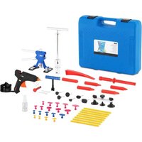
This manual contains instructions and safety information for installation, operation and maintenance of the MSW Motor Technics Dent Tool Kit.
This manual is intended for:
• The end user of the product.
1.2. Languages
This manual was originally written in the English language. All other languages are translations from the English document.
2. Product
2.1. Intended use
• This product is intended for paintless dent repair from motor vehicle body panels.
- Only use the product as described in this manual.
• This product is intended for indoor use only.
• This product can be used by end users from 18 years old and above.
2.2. Foreseeable misuse
• This product is not intended for outdoor use.
- This product is not intended to transport while the power cable is plugged in.
2.3. Disclaimer
Any use of the product other than described in this manual is regarded as misuse and may cause injury, damage to the product and void the warranty.
2.4. General specifications
| Product name | Dent Tool Kit | ||
| Product number | 10061540 | 10061541 | 10061542 |
| Model | MSW-DA-12 | MSW-DA-13 | MSW-DA-14 |
| Dimensions (I x w x h) | 220 x110 x 200 mm | 430x120x 370 mm | 190 x 100 x 210 mm |
| Weight | 1.48 kg | 4.6 kg | 1 kg |
| Rated voltage and frequency | 220 - 240 V ~ 50 Hz | 220 - 240 V ~ 50 Hz | 220 - 240 V ~ 50 Hz |
| Rated power | 40 W | 100 W | 100 W |
| Operating temperature | 10°C - 30 °C | 10 °C - 30 °C | 10 °C - 30 °C |
| Operating humidity | 30% - 80% | 30% - 80% | 30% - 80% |
| Protection class | Class II | Class II | Class II |
| Protection rating IP | IPX0 | IPX0 | IPX0 |
2.5. Type plates
The type plate can be found on the packaging of the product.
2.5.1. 10061540
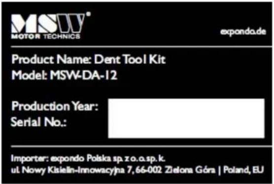
text_image
MSW® MOTOR TECHNICS expondo.de Product Name: Dent Tool Kit Model: MSW-DA-12 Production Year: Serial No.: Importer: expondo Polska sp.zo.o.sp.k. ul Nowy Kisielin-Innowacyjna 7,66-002 Zielona Góra | Poland, EU2.5.2. 1006 1541
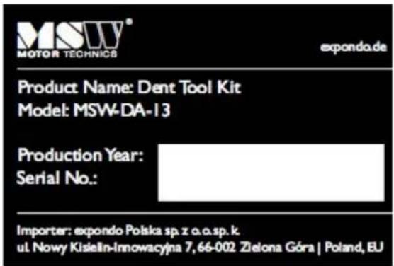
text_image
MSUV® MOTOR TECHNICS expanda.de Product Name: Dent Tool Kit Model: MSW-DA-13 Production Year: Serial No.: Importer: expondo Polska sp. z o.o.sp. k. ul. Nowy Kisieln-Innowacyjna 7, 66-002 Zielona Góra | Poland, EU2.5.3. 1006 1542
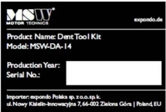
text_image
MSUV® MOTOR TECHNICS expondo.de Product Name: Dent Tool Kit Model: MSW-DA-14 Production Year: Serial No.: Importer: expondo Polska sp. zo.o.sp.k. ul. Nowy Kisielin-Innowacyjna 7,66-002 Zielona Góra | Poland, EU3. Description and operation
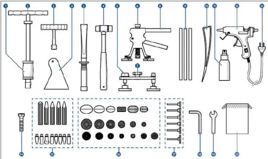
3.1. Main parts
text_image
Technical diagram of a spray gun assembly with numbered parts and exploded view of tool packages- T-Bar puller
- T-Bar
- Sc raper 1) 2)
- H ammer
- Bridge puller 2)
- D ent lifter knob
- Bridge puller knob 2)
- D ent lifter
- Glue sticks
- Tap down tool
- Spray bottle ^1) ^2)
- Glue gun
- Power cable
- Knock down pen 1)2)
- Knock down tips ^1) ^2)
- Dent removal tabs
- Dent removal attachments 2)
- Hex key ^1)
- Wrench ^1)
- Pouch 1)
4. Safety
4.1. Personal protective equipment
It is mandatory to wear the following personal protective equipment when using the product:
| Icon | Description | |
 | Wear protective gloves. | |
 | Wear safety goggles. | |
 | Wear a safety helmet. | |
4.2. Symbols on the product or packaging
| Icon | Description | |
 | This symbol indicates that this product may not be disposed with household waste. Recycle this product in an environmentally friendly manner according to local regulations. | |
 | This symbol indicates that the product is CE certified. | |
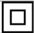 | This symbol indicates that the product is a class II electrical product. |
4.3. Safety instructions
| Signal word | Description |
| ⚠WARNING | Signal word used to indicate a potentially hazardous situation which, if not avoided, could result in death or serious injury. |
| ⚠CAUTION | Signal word used to indicate a potentially hazardous situation which, if not avoided, could result in minor or moderate injury. |
| NOTICE | Indicates important information that is not directly related to safety. |
| i | Indicates useful information. |
4.3.1. General safety instructions
WARNING
- Safety hazard. Always fully read and understand the instructions in this manual before you install, use, or maintain the product. When the manual is not fully read, understood, or followed, this can cause serious injury.
CAUTION
- Safety hazard. Never use the product if a part is damaged or defective. Replace a damaged or defective product immediately. Using a defective product can cause moderate injury.
4.3.2. Transport and storage
NOTICE
- Risk of damaging the product. Always store the product in a clean, dry, and enclosed place when the product is not used for a longer period of time. Incorrect storage of the product may cause defects.
4.3.3. Installation
NOTICE
Risk of damaging the product:
- Risk of physical shock of the product. Never drop the product. Always avoid bumping. Dropping the product may cause damage to the product or the internal electrical parts.
- Risk of damaging the product. Never leave the power cable hanging over the edge of a table or counter. Prevent the product from being pulled down. Pulling the power cable may cause damage to the product.
4.3.4. Use
▲WARNING
- Fire hazard caused by short-circuiting. Always check if the voltage stated on the type plate of the product matches with the power outlet voltage.
- Electrical shock hazard caused by short-circuiting. Always connect the power cable to a grounded power outlet.
- Fire hazard caused by the product that can become hot during use. Never use the product near flammable materials or surfaces. Always keep the product at a minimum distance of 1 meter from flammable materials or surfaces.
- Electrical shock hazard. Never use the product when the power cable is damaged. Always replace a damaged power cable with an original power cable available from the manufacturer or the supplier.
CAUTION
- Burning hazard caused by surfaces that may become hot while the product is in use. Never touch the hot surfaces of the product. The glue gun tip becomes hot while in use.
4.3.5. Maintenance
▲WARNING
- Electrical shock hazard. Never immerse the product in water or other liquids. Follow the cleaning instructions in this manual for the correct performance of maintenance.
• Electrical shock hazard. Never handle the product with wet hands. - Electrical shock hazard. Never perform any maintenance with the power cable connected to a power outlet. Always disconnect the power cable from the power outlet before cleaning the product.
- Electrical shock hazard. Never replace the power cable yourself. Always have the power cable replaced by the manufacturer, a service agent or similar qualified persons.
NOTICE
- Risk of damaging the product. Never use cleaning solvents or abrasives to clean the product. Always use the correct cleaning method specified in this manual. Using incorrect cleaning solvents or abrasives may cause damage to the product.
4.3.6. Children and disabled
▲WARNING
- Choking hazard. Never let children play with the packaging material. Always keep the packaging material out of reach of children. Playing with packaging material may cause serious injury or death.
CAUTION
- Burning hazard caused by surfaces that may become hot while the product is in use. Never let children alone unattended when the product is in use. Always supervise children when the product is in use.
5. Storage
Store the product in a clean, dry and enclosed place when the product is not used for a longer period of time.
6. Installation
6.1. Package contents
- Remove the product from the packaging and remove the packaging material.
- Check if all parts are present and if no parts damaged.
If any parts are missing or damaged, please contact your supplier.
6.1.1. 10061540
| 1x | Dent lifter |
| 1x | Glue gun |
| 1x | Hammer |
| 1x | T-Bar |
| 1x | Knock down pen |
| 1x | Spray bottle |
| 1x | Scraper |
| 10x | Glue sticks |
| 19x | Dent removal tabs |
| 8x | Knock down tips |
| 1x | Cotton cloth bag |
6.1.2. 10061541
| 1x | Dent lifter |
| 1x | Bridge puller |
| 1x | T-Bar |
| 1x | Glue gun |
| 1x | Knock down pen |
| 1x | Spray bottle |
| 1x | Scraper |
| 8x | Glue sticks |
| 19x | Dent removal tabs |
| 5x | Dent removal attachments |
| 6x | Knock down tips |
| 1x | Casing |
6.1.3. 10061542 & 10061543
| 1x | Dent lifter |
| 1x | Glue gun |
| 10x | Glue sticks |
| 18x | Dent removal tabs |
6.2. Requirements for the location of installation
Install the product in a location that meets the following requirements:
- Dry environment.
- Away from heat sources and highly inflammable liquids at a minimum distance of 1 meter.
• Near a power outlet. - Easily accessible by the end user.
7. Use
7.1. Before use
- Fill the spray bottle [#] with rubbing alcohol.
- Spray some rubbing alcohol with the spray bottle [#] on the area with the dent to degreas e the body panel.
- Wipe the body panel dry with a soft, dry cloth.
- Remove any glue residue from the dent removal tabs [#].
7.2. Switching on and starting up
▲WARNING
- Fire hazard caused by short-circuiting. Always check if the voltage stated on the type plate of the product matches with the power outlet voltage.
- Electrical shock hazard caused by short-circuiting. Always connect the power cable to a grounded power outlet.
-
Fire hazard caused by the product that can become hot during use. Never use the product near flammable materials or surfaces. Always keep the product at a minimum distance of 1 meter from flammable materials or surfaces.
-
Insert a glue stick [#] in the glue gun [#].
- Plug the power cable [#] into a power outlet.
The glue gun [#] is now switched on. - Allow the glue gun to heat up for approximately 3 - 5 minutes.
7.3. Using the product
7.3.1. Using the dent removal tabs
CAUTION
- Burning hazard caused by surfaces that may become hot while the product is in use. Never touch the hot surfaces of the product. The glue gun tip becomes hot while in use.
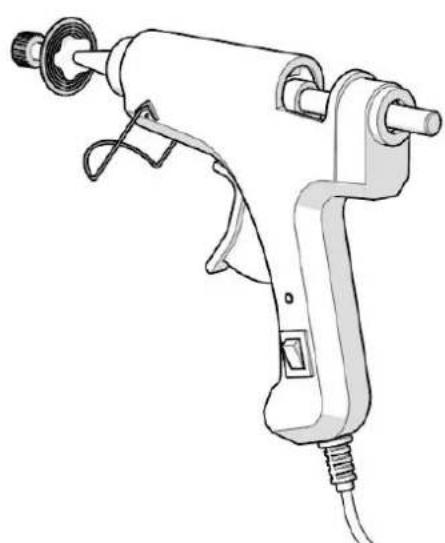
- Choose a dent removal tab [#] which is roughly the same shape as the dent, but slightly smaller than the dent.
natural_image
Line drawing of a handheld electric tool with nozzle and cable (no text or symbols)-
Apply a small amount of glue on the dent removal tab [#] with the glue gun [#]. Leave approximately 5 mm of free space around the edge of the dent removal tab [#].
-
P lace the dent removal tab [#] on the area of the dent.
-
Apply a small amount of pressure on the dent removal tab [#] to ensure that the glu e spreads underneath the dent removal tab [#] and sticks to the body panel.
Do not apply too much pressure. This can cause the glue to push out of the sides of the dent removal tab [#].
- Wait a few minutes for the glue to harden. The glue is fully hardened when the dent removal tab [#] has fully cooled down.
The drying time of the glue depends on the temperature of the working environment.
natural_image
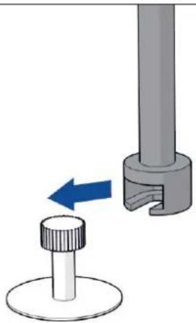
Diagram showing a mechanical component with a blue arrow indicating direction, no text or symbols present- Place the T-Bar [#] or dent lifter [#] over the dent removal tab [#].
For the bridge puller [#], insert the dent removal attachment [#] into the bridge puller [#].
i Use the T-Bar [#] for large sized dents (up to 49 mm).
Use the bridge puller [#] for medium sized dents (up to 39 mm).
Use the dent lifter [#] for small sized dents (up to 30 mm).
- To remove the dent from the body panel:
natural_image
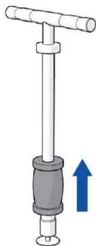
Mechanical device with a lever and a blue upward arrow indicating motion (no text or symbols)• Using the T-Bar [#]:
- Pull the T-Bar handle and slide the T-Bar puller back and forth to lift the dent.
- Repeat until the dent is fully lifted.
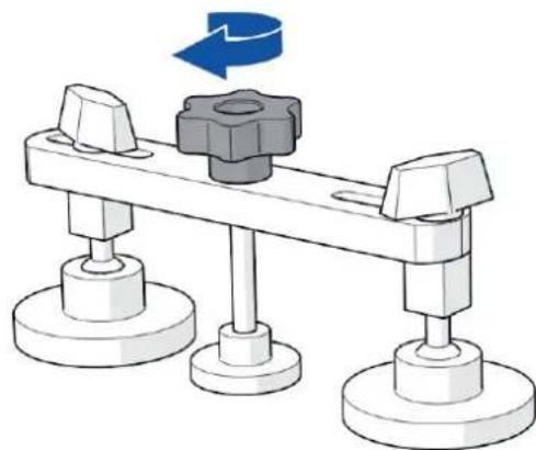
natural_image
Mechanical assembly diagram showing a lever mechanism with three base plates and a central gear (no text or symbols)• Using the bridge puller [#]:
-
Rotate the bridge puller knob [#] slowly counter clockwise to lift the dent.
-
Repeat until the dent is fully lifted.
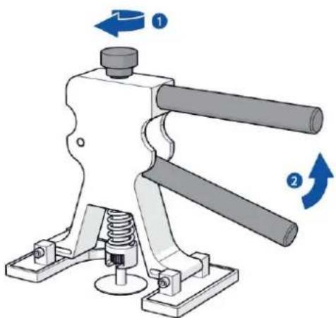
natural_image
Mechanical clamp device with two rotating arms and a spring base (no text or symbols)• Using the dent lifter [#]:
-
Adjust the dent lifter knob [#] to adjust the lifting strength.
-
Squeeze the two handles of the dent lifter [#] together to lift the dent.
-
Ro tate the dent lifter [#] clockwise to differ the support points on the body panel and to evenly lift the dent.
-
Repeat step 2 and 3 until the dent is fully lifted.
-
Remove the T-Bar [#], bridge puller [#], or dent lifter [#] from the dent removal tab [#].
-
Spray some rubbing alcohol with the spray bottle [#] onto the dent removal tab [#] to release the dent removal tab [#] from the body panel.
-
Carefully remove the dent removal tab [#] by hand or with the scraper [#] from the body panel.
-
Wipe the body panel dry with a soft, dry cloth.
-
Inspect the area of the dent. If a smaller dent is left on the body panel, repeat steps 1 to 11 again with a smaller dent removal tab [#] until the dent is completely removed.
7.3.2. Using the knock down tips
This chapter only applies to 10061540 and 10061541.
It may occur that the dent has inverted outwards after using the dent removal tabs. Using the knock down tips, the inverted dent can be knocked down to flatten the body panel.
- Insert a knock down tip [#] into the knock down pen [#].
i Use the rounded knock down tips to knock down smooth dents.
i Use the pointed knock down tips to knock down sharp dents. - Place the knock down tip onto the inverted dent .
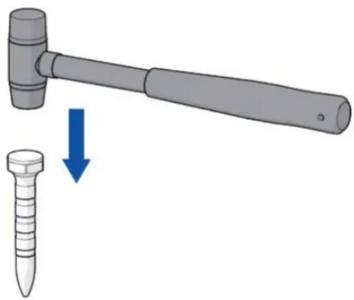
natural_image
Illustration of a hammer striking a screw with a blue arrow indicating the process (no text or symbols present)- Tap the knock down tip [#] with the hammer [#] to flatten the inverted dent.
7.4. Switching off
- Unplug the power cable [#] from the power outlet.
The glue gun [#] is now switched off.
Allow the glue gun [#] to cool down completely.
8. Maintenance
8.1. Cleaning the product
WARNING
- Electrical shock hazard. Never perform any maintenance with the power cable connected to a power outlet. Always disconnect the power cable from the power outlet before cleaning the product.
It is recommend to clean the product once a year.
- Unplug the power cable [#] from the power outlet.
Allow the glue gun [#] to cool down for at least # minutes.
- Clean the dent removal tabs [#] and glue gun [#] with rubbing alcohol and a scraper [#] or cloth.
8.2. Ordering spare parts
For spare parts or replacements, please contact the Expondo service desk.
The following spare parts can be ordered:
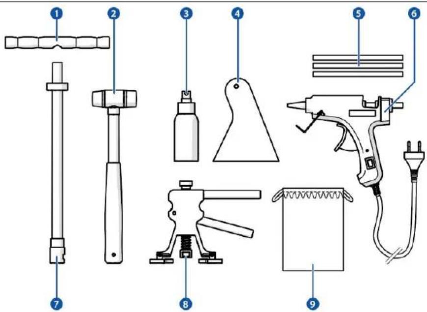
text_image
Labeled diagram of various hair tools and accessories, including a spray gun, tool holder, and electrical plug.| Part | Article number |
| 1. T-Bar handle | N840002 |
| 2. Hammer | N840014 |
| 3. Spray bottle | N840039 |
| 4. Scraper | N840040 |
| 5. Glue sticks | N840041 |
| 6. Glue gun | N840004 |
| 7. T-Bar attachment | N840003 |
| 8. Dent lifter | N840001 |
| 9. Pouch | N840042 |
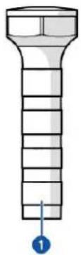
natural_image
Illustration of a screw with a blue arrow pointing to the bottom center (no text or symbols)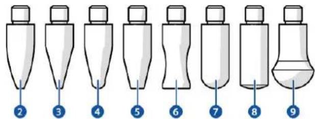
text_image
Diagram showing nine labeled stages of a laboratory bottle or pipette with numbered callouts pointing to each stage.| Part | Article number |
| 1. Knock down pen | N840005 |
| 2. Knock down tip 1 | N840006 |
| 3. Knock down tip 2 | N840007 |
| 4. Knock down tip 3 | N840008 |
| 5. Knock down tip 4 | N840009 |
| 6. Knock down tip 5 | N840010 |
| 7. Knock down tip 6 | N840011 |
| 8. Knock down tip 7 | N840012 |
| 9. Knock down tip 8 | N840013 |
text_image
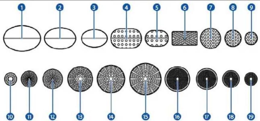
Diagram showing 19 circular patterns with numbered labels, likely illustrating a pattern or design concept.| Part | Article number |
| 1. 47.5 x 32.6 mm dent removal tab | N840021 |
| 2. 40 x 27.1 mm dent removal tab | N840022 |
| 3. 32.9 x 22.3 mm dent removal tab | N840023 |
| 4. 39.61 x 24.8 mm dent removal tab | N840034 |
| 5. 29.3 x 19.7 mm dent removal tab | N840030 |
| 6. 31.7 x 16.6 mm dent removal tab | N840024 |
| 7. 25.9 mm dent removal tab | N840032 |
| 8. 20.8 mm dent removal tab | N840031 |
| 9. 15.9 mm dent removal tab | N840033 |
| 10. 15.2 mm dent removal tab | N840015 |
| 11. 19.8 mm dent removal tab | N840016 |
| 12. 24.6 mm dent removal tab | N840017 |
| 13. 31.6 mm dent removal tab | N840018 |
| 14. 35.1 mm dent removal tab | N840019 |
| 15. 40.2 mm dent removal tab | N840020 |
| 16. 32 mm dent removal tab | N840035 |
| 17. 28 mm dent removal tab | N840036 |
| 18. 22 mm dent removal tab | N840037 |
| 19. 16 mm dent removal tab | N840038 |
9. Troubleshooting
| Problem | Possible cause | Possible solution |
| The product does not work. | The power cable [#] is not plugged in. | Plug the power cable [#] into a power outlet. |
| The glue gun takes too long to heat up. | The nozzle is blocked by glue residue. | 1. Allow the glue gun to cool down.2. Remove the glue residue from the nozzle. |
| Unsuitable glue sticks are used with the glue gun. | 1. Allow the glue gun to cool down.2. Remove the glue stick from the glue gun.3. Insert a suitable glue stick into the glue gun. |
10. Disposal
If the product is defective, please contact the Expondo service desk. It may still be possible to repair the product. If you still need to dispose the product, please follow the local regulations.
11. Warranty
This product comes with a warranty period of 36 months from the moment of purchase.
Any changes and/or modifications to the product will void the warranty. Expondo accepts no liability for damage caused by improper use of the product.
For more information, consult: https://www.expondo.co.uk/warranty-conditions/
MSW Motor Technics
natural_image
Technical line drawing of a mechanical clamp or lever device with no visible text or symbolsExpondo GmbH
Köpenicker Str. 54
10179 Berlin
Niemcy
text_image
Technical diagram of a spray gun assembly with numbered parts and exploded view of tool packagesnatural_image
Line drawing of a handheld electric tool with nozzle and handle (no text or symbols)natural_image
Diagram showing a mechanical component with a blue arrow indicating direction, no text or symbols presentnatural_image
Mechanical device with a lever and a blue upward arrow indicating motion (no text or symbols)natural_image
Mechanical assembly diagram showing a lever mechanism with three base plates and a central gear (no text or symbols)natural_image
Mechanical device with two shafts and a spring base, showing rotational arrows (no text or symbols)natural_image
Illustration of a hammer striking a screw with a blue arrow indicating the process (no text or symbols present)text_image
Labeled diagram of various hair tools and accessories, including a spray gun, tool holder, and electrical plug.natural_image
Illustration of a screw with a blue arrow pointing to the bottom center (no text or symbols)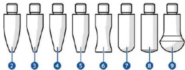
text_image
Diagram showing nine labeled stages of a laboratory bottle or pipette with numbered callouts pointing to each stage.text_image
Diagram showing 19 circular patterns with numbered labels, likely illustrating a pattern or design concept.| Część | Numer artykułu |
| 1. Grzybek 47,5 x 32,6 mm | N840021 |
| 2. Grzybek 40 x 27,1 mm | N840022 |
| 3. Grzybek 32,9 x 22,3 mm | N840023 |
| 4. Grzybek 39,61 x 24,8 mm | N840034 |
| 5. Grzybek 29,3 x 19,7 mm | N840030 |
| 6. Grzybek 31,7 x 16,6 mm | N840024 |
| 7. Grzybek 25,9 mm | N840032 |
| 8. Grzybek 20,8 mm | N840031 |
| 9. Grzybek 15,9 mm | N840033 |
| 10. Grzybek 15,2 mm | N840015 |
| 11. Grzybek 19,8 mm | N840016 |
| 12. Grzybek 24,6 mm | N840017 |
| 13. Grzybek 31,6 mm | N840018 |
| 14. Grzybek 35,1 mm | N840019 |
| 15. Grzybek 40,2 mm | N840020 |
| 16. Grzybek 32 mm | N840035 |
| 17. Grzybek 28 mm | N840036 |
| 18. Grzybek 22 mm | N840037 |
| 19. Grzybek 16 mm | N840038 |
natural_image
Technical line drawing of a mechanical clamp or lever device with no visible text or symbolsExpondo GmbH
Köpenicker Str. 54
10179 Berlin
Německo
text_image
Technical diagram of a spray gun assembly with numbered parts and component layouts for each part.natural_image
Line drawing of a handheld electric tool with nozzle and cable (no text or symbols)natural_image
Diagram showing a mechanical component with a blue arrow pointing to a circular feature, no text or symbols present.natural_image
Diagram of a mechanical device with a lever and a blue upward arrow indicating motion (no text or symbols)natural_image
Mechanical assembly diagram showing a rotating gear mounted on a lever with three base supports (no text or symbols)natural_image
Mechanical device with two shafts and a spring base, showing rotational motion arrows (no text or symbols)natural_image
Illustration of a hammer striking a screw with a blue arrow indicating the process (no text or symbols present)text_image
Diagram of various hair tools with numbered labels for identificationnatural_image
Illustration of a mechanical screw with a blue arrow pointing to a numbered component (no text or symbols present)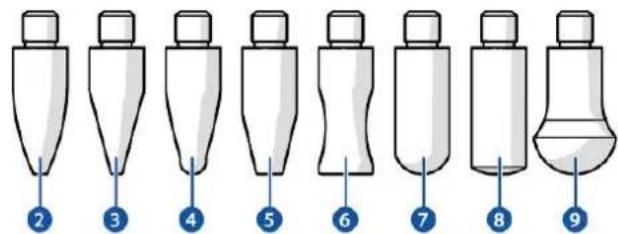
text_image
Diagram showing nine labeled stages of a laboratory bottle or pipette with numbered callouts pointing to each stage.text_image
Diagram showing 19 circular patterns with numbered labels, likely illustrating a pattern or design concept.| Díl | Číslo zboží |
| 1. Hříbek 47,5 x 32,6 mm | N840021 |
| 2. Hříbek 40 x 27,1 mm | N840022 |
| 3. Hříbek 32,9 x 22,3 mm | N840023 |
| 4. Hříbek 39,61 x 24,8 mm | N840034 |
| 5. Hříbek 29,3 x 19,7 mm | N840030 |
| 6. Hříbek 31,7 x 16,6 mm | N840024 |
| 7. Hříbek 25,9 mm | N840032 |
| 8. Hříbek 20,8 mm | N840031 |
| 9. Hříbek 15,9 mm | N840033 |
| 10. Hříbek 15,2 mm | N840015 |
| 11. Hříbek 19,8 mm | N840016 |
| 12. Hříbek 24,6 mm | N840017 |
| 13. Hříbek 31,6 mm | N840018 |
| 14. Hříbek 35,1 mm | N840019 |
| 15. Hříbek 40,2 mm | N840020 |
| 16. Hříbek 32 mm | N840035 |
| 17. Hříbek 28 mm | N840036 |
| 18. Hříbek 22 mm | N840037 |
| 19. Hříbek 16 mm | N840038 |
9. Řešení problémů
natural_image
Technical line drawing of a mechanical clamp or lever device with no visible text or symbolsExpondo GmbH
Köpenicker Str. 54
10179 Berlin
Allemagne
1. Introduction....3
text_image
Technical diagram of a spray gun assembly with numbered parts and component layouts for each part.natural_image
Line drawing of a handheld electric tool with nozzle and cable (no text or symbols)natural_image
Diagram showing a mechanical component with a blue arrow indicating direction, no text or symbols presentnatural_image
Diagram of a mechanical device with a lever and a blue upward arrow indicating motion (no text or symbols)natural_image
Mechanical assembly diagram showing a lever mechanism with three base plates and a central gear (no text or symbols)natural_image
Mechanical clamp device with two rotating arms and a spring base (no text or symbols)natural_image
Illustration of a hammer striking a screw with a blue arrow indicating the process (no text or symbols present)text_image
Labeled diagram of various hair tools and accessories, including a spray gun, tool holder, and electrical plug.natural_image
Illustration of a bolt with a numbered marker (1) pointing to the bottom section, no text or symbols present.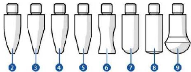
text_image
Diagram showing nine labeled stages of a laboratory bottle or pipette with numbered callouts pointing to each stage.text_image
Diagram showing 19 circular patterns with numbered labels, likely illustrating a pattern or design concept.| Pièce | Numéro de référence |
| 1. Embout 47,5 x 32,6 mm | N840021 |
| 2. Embout 40 x 27,1 mm | N840022 |
| 3. Embout 32,9 x 22,3 mm | N840023 |
| 4. Embout 39,61 x 24,8 mm | N840034 |
| 5. Embout 29,3 x 19,7 mm | N840030 |
| 6. Embout 31,7 x 16,6 mm | N840024 |
| 7. Embout 25,9 mm | N840032 |
| 8. Embout 20,8 mm | N840031 |
| 9. Embout 15,9 mm | N840033 |
| 10. Embout 15,2 mm | N840015 |
| 11. Embout 19,8 mm | N840016 |
| 12. Embout 24,6 mm | N840017 |
| 13. Embout 31,6 mm | N840018 |
| 14. Embout 35,1 mm | N840019 |
| 15. Embout 40,2 mm | N840020 |
| 16. Embout 32 mm | N840035 |
| 17. Embout 28 mm | N840036 |
| 18. Embout 22 mm | N840037 |
| 19. Embout 16 mm | N840038 |
natural_image
Technical line drawing of a mechanical clamp or lever device with no visible text or symbolsExpondo GmbH
Köpenicker Str. 54
10179 Berlin
Germania
text_image
Technical diagram of a spray gun assembly with numbered parts and component layouts for each part.natural_image
Line drawing of a handheld electric tool with nozzle and cable (no text or symbols)natural_image
Diagram showing a mechanical component with a blue arrow indicating direction, no text or symbols presentnatural_image
Mechanical device with a lever and a blue upward arrow indicating motion (no text or symbols)natural_image
Mechanical assembly diagram showing a lever mechanism with three base plates and a central gear (no text or symbols)natural_image
Mechanical clamp device with two shafts and a spring base, showing rotational direction indicators (no text or symbols)natural_image
Illustration of a hammer striking a screw with a blue arrow indicating the process (no text or symbols present)text_image
Labeled diagram of various hair tools and accessories, including a spray gun, tool holder, and electrical plug.natural_image
Illustration of a mechanical screw with a blue arrow pointing to a numbered component (no text or symbols present)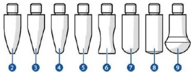
text_image
Diagram showing nine labeled stages of a laboratory bottle or pipette with numbered callouts pointing to each stage.text_image
Diagram showing 19 circular patterns with numbered labels, likely illustrating a pattern or design concept.| Parte | Numero di articolo |
| 1. Fungo 47,5 x 32,6 mm | N840021 |
| 2. Fungo 40 x 27,1 mm | N840022 |
| 3. Fungo 32,9 x 22,3 mm | N840023 |
| 4. Fungo 39,61 x 24,8 mm | N840034 |
| 5. Fungo 29,3 x 19,7 mm | N840030 |
| 6. Fungo 31,7 x 16,6 mm | N840024 |
| 7. Fungo 25,9 mm | N840032 |
| 8. Fungo 20,8 mm | N840031 |
| 9. Fungo 15,9 mm | N840033 |
| 10. Fungo 15,2 mm | N840015 |
| 11. Fungo 19,8 mm | N840016 |
| 12. Fungo 24,6 mm | N840017 |
| 13. Fungo 31,6 mm | N840018 |
| 14. Fungo 35,1 mm | N840019 |
| 15. Fungo 40,2 mm | N840020 |
| 16. Fungo 32 mm | N840035 |
| 17. Fungo 28 mm | N840036 |
| 18. Fungo 22 mm | N840037 |
| 19. Fungo 16 mm | N840038 |
natural_image
Technical line drawing of a mechanical clamp or lever device with no visible text or symbolsExpondo GmbH
Köpenicker Str. 54
10179 Berlin
Alemania
EN – Lengua original
V00_01-12/2021
Índice
text_image
Technical diagram of a spray gun assembly with numbered parts and component layouts for each part.natural_image
Line drawing of a handheld electric spray gun with nozzle and handle (no text or symbols)natural_image
Diagram showing a mechanical component with a blue arrow indicating direction, no text or symbols presentnatural_image
Diagram of a mechanical device with a blue upward arrow indicating force or direction (no text or symbols present)natural_image
Mechanical assembly diagram showing a lever mechanism with three base plates and a central gear (no text or symbols)• Utilizando pullera [#]:
natural_image
Mechanical clamp device with two shafts and a spring base, showing rotational motion arrows (no text or symbols)natural_image
Illustration of a hammer striking a screw with a blue arrow indicating the process (no text or symbols present)text_image
Diagram of various hair tools with numbered labels for identificationnatural_image
Illustration of a screw with a numbered indicator (1) pointing to the bottom section, no text or symbols present.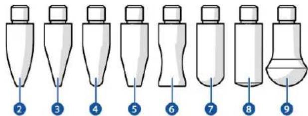
text_image
Diagram showing nine labeled stages of a laboratory bottle or pipette with numbered callouts.text_image
Diagram showing 19 circular patterns with numbered labels, likely illustrating a pattern or design concept.| Componente | Número de artículo |
| 1. Lengüeta 47,5 x 32,6 mm | N840021 |
| 2. Lengüeta 40 x 27,1 mm | N840022 |
| 3. Lengüeta 32,9 x 22,3 mm | N840023 |
| 4. Lengüeta 39,61 x 24,8 mm | N840034 |
| 5. Lengüeta 29,3 x 19,7 mm | N840030 |
| 6. Lengüeta 31,7 x 16,6 mm | N840024 |
| 7. Lengüeta 25,9 mm | N840032 |
| 8. Lengüeta 20,8 mm | N840031 |
| 9. Lengüeta 15,9 mm | N840033 |
| 10. Lengüeta 15,2 mm | N840015 |
| 11. Lengüeta 19,8 mm | N840016 |
| 12. Lengüeta 24,6 mm | N840017 |
| 13. Lengüeta 31,6 mm | N840018 |
| 14. Lengüeta 35,1 mm | N840019 |
| 15. Lengüeta 40,2 mm | N840020 |
| 16. Lengüeta 32 mm | N840035 |
| 17. Lengüeta 28 mm | N840036 |
| 18. Lengüeta 22 mm | N840037 |
| 19. Lengüeta 16 mm | N840038 |
text_image
Technical diagram of a spray gun assembly with numbered parts and component layouts for each part.natural_image
Line drawing of a handheld electric tool with nozzle and handle (no text or symbols)natural_image
Diagram showing a mechanical component with a blue arrow indicating direction, no text or symbols presentnatural_image
Mechanical device with a lever and a blue upward arrow indicating motion (no text or symbols)natural_image
Illustration of a hammer striking a screw with a blue arrow indicating the process (no text or symbols present)natural_image
Illustration of a bolt with a numbered marker (1) pointing to the bottom section, no text or symbols present.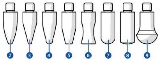
text_image
Diagram showing nine labeled stages of a laboratory bottle or pipette with numbered callouts pointing to each stage.text_image
Diagram showing 19 circular patterns with numbered labels, likely illustrating a pattern or design concept.natural_image
Technical line drawing of a mechanical clamp or lever device with no visible text or symbolsExpondo GmbH
Köpenicker Str. 54
10179 Berlin
Tyskland
ENG - Originalsprog
V00_01 / 12-2021
Indholdsfortegnelse
1. Indledning....3
1.1. Om dette dokument .... 3
1.2.Sprog. 3
2. Produkt 3
text_image
Technical diagram of a spray gun assembly with numbered parts and component layouts for each part.natural_image
Line drawing of a handheld electric tool with nozzle and handle (no text or symbols)natural_image
Mechanical assembly diagram showing a pin and lever mechanism with a blue arrow indicating motion (no text or symbols)natural_image
Diagram of a mechanical device with a lever and a blue upward arrow indicating motion (no text or symbols)• Med en glidehammer [#]:
natural_image
Mechanical assembly diagram showing a lever mechanism with three base plates and a central gear (no text or symbols)• Med en puller [#]:
natural_image
Mechanical device with two shafts and a spring base, showing rotational motion arrows (no text or symbols)natural_image
Illustration of a hammer striking a screw with a blue arrow indicating the process (no text or symbols present)text_image
Labeled diagram of various hair tools and accessories, including a spray gun, tool holder, and electrical plug.| Reservedel | Artikelnummer |
| 1. Håndtag | N840002 |
| 2. Hammer | N840014 |
| 3. Sprayflaske | N840039 |
| 4. Skraber | N840040 |
| 5. Limpinde | N840041 |
| 6. Limpistol | N840004 |
| 7. Adapter til glidehammer | N840003 |
| 8. Buleudtrækker | N840001 |
| 9. Emballage | N840042 |
natural_image
Illustration of a mechanical screw with a blue arrow pointing to a numbered component (no text or symbols present)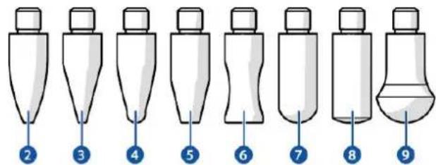
text_image
Diagram showing nine labeled stages of a laboratory bottle or pipette with numbered callouts pointing to each stage.text_image
Diagram showing 19 circular patterns with numbered labels, likely illustrating a pattern or design concept.| Reservedel | Artikelnummer |
| 1. Limplade 47,5 x 32,6 mm | N840021 |
| 2. Limplade 40 x 27,1 mm | N840022 |
| 3. Limplade 32,9 x 22,3 mm | N840023 |
| 4. Limplade 39,61 x 24,8 mm | N840034 |
| 5. Limplade 29,3 x 19,7 mm | N840030 |
| 6. Limplade 31,7 x 16,6 mm | N840024 |
| 7. Limplade 25,9 mm | N840032 |
| 8. Limplade 20,8 mm | N840031 |
| 9. Limplade 15,9 mm | N840033 |
| 10. Limplade 15,2 mm | N840015 |
| 11. Limplade 19,8 mm | N840016 |
| 12. Limplade 24,6 mm | N840017 |
| 13. Limplade 31,6 mm | N840018 |
| 14. Limplade 35,1 mm | N840019 |
| 15. Limplade 40,2 mm | N840020 |
| 16. Limplade 32 mm | N840035 |
| 17. Limplade 28 mm | N840036 |
| 18. Limplade 22 mm | N840037 |
| 19. Limplade 16 mm | N840038 |